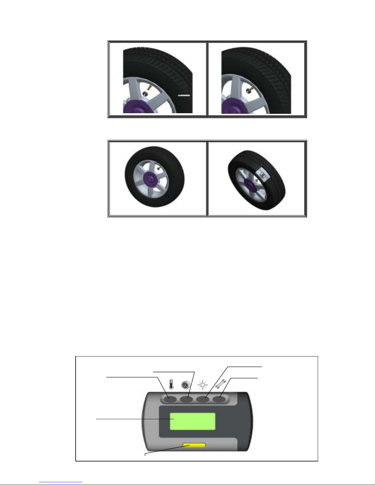
7. Alarms and Warnings
7.1 Pressure Threshold Alarm and Warning
Should Programming Manual
Threshold Setting Limit are 25psi
and 75℃respectively while
ctory-preset value are 23psi and
85℃:
fa
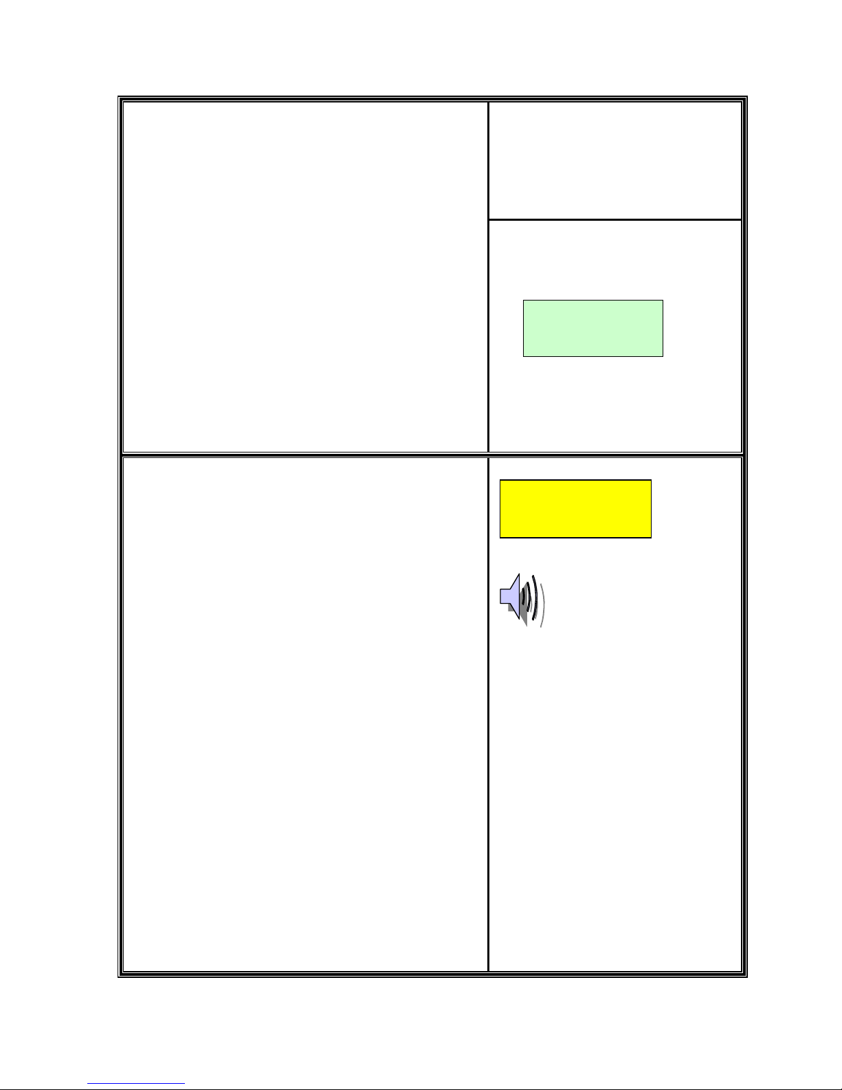
9.1.1 Tire pressure lower than Manual
Pressure Threshold Setting:
A Low Pressure Warning is initiated when
the pressure drops below the
programmed Pressure Threshold Setting
Limit。
1. WarningActions Include:
1st. LED Alarming Indicator
blinks once。
2nd. An short audio alarm。
2. Suggested Action to Warning:
1st. When the warning occurs,
reduce speed and proceed to a
safe location to check tires。
1.LCD Display will remain normal
when measured pressure is
24psi.
Tire pressure drops below
Factory-Preset Pressure Threshold
Setting:
A Low Pressure Alarm is initiated when the
pressure drops below Factory-Preset
Threshold Setting Limit,i.e. 23psi。
Alarm Actions Include:
1. Affected tire/s with its corresponding
Pressure digit/s kept on flashing。
2. An long audio alarm。
3. LCD Display Backlight remains on;
LED Alarming Indicator remains on。
Cancel Alarm Temporarily:
1. Proceed “Reset” as depicted on
“General Set Up Mode” Section c。
Suggested Action to Alarm:
1. When the alarm occurs,reduce speed
and proceed to a safe location to
check tires。
Note:The Pressure Deviation Alarm will
disappear when the tires are properly
re-inflated to correct levels。
a.
b.
c.
d.
e.
30P 32P
32P 24P
31P !20P
30P 30P
Note: Value shown above is for reference only.