Installation Installation
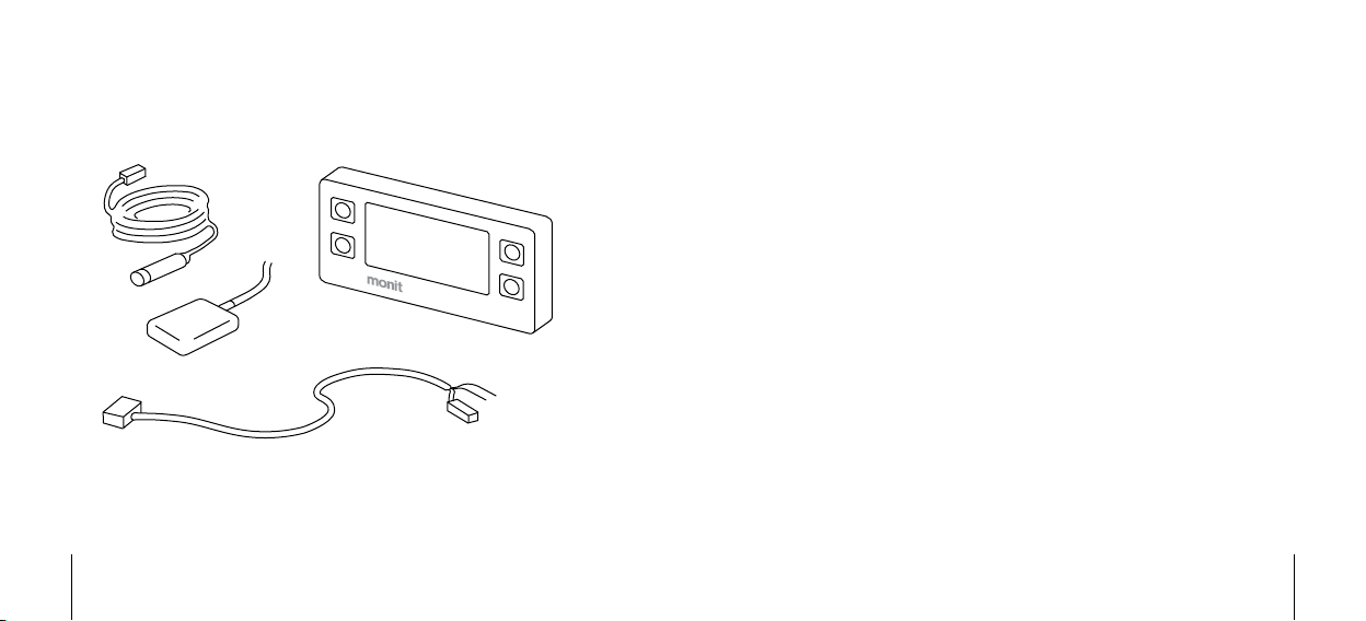
GPS/GNSS Antenna
If GPS/GNSS is going to be used to measure speed and distance you will need
to fit a suitable antenna. There is a range of these available from Monit. The
antenna attaches to the device using the SMA connector on the back. Refer to
the information supplied with your antenna for detailed instructions.
Wheel Speed Sensor
If GPS/GNSS is not going to be used, or you want to make use of the GPS/
GNSS+ sensor fusion technology (see Page 4), you will need to supply a wheel
speed signal to the rally computer. There is a special connector on the wiring
loom for this purpose. It will connect directly to the range of wheel sensors
available from Monit, and detailed installation instructions are supplied with
each sensor.
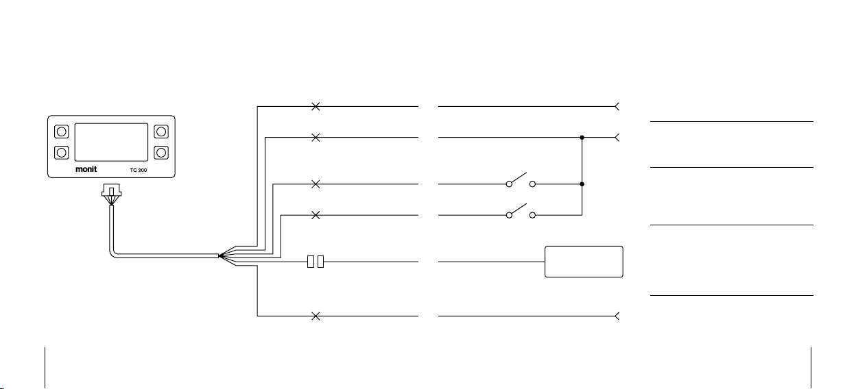
Auxiliary Inputs
These can be used to attach up to two hand or foot switches to the unit. You
can then configure each switch to perform a range of useful functions, such
as clearing the distance or controlling the stopwatch. For most functions a
normally-off momentary type switch should be used.
See page 32 for more information.
Fuel Sender Signal (G-200+ only)
To use the G-200+’s fuel measurement system, connect the output signal from
your vehicle’s fuel sender directly to the green wire on the loom.
Points to note during installation are:
The G-200+ works by measuring the output voltage of your vehicle’s fuel•
sender. It can be used with signals that either rise or fall with increasing
fuel level.
If you remove your factory fuel gauge you will need to fit a resistor of•
approximately the same value in its place to power the sender.
Many factory fuel senders will not produce an output signal when the•
ignition is turned off.