Monit Rally TC100 How to use

TC100
Operation & Installation Guide
Revision 1.1

© 2006—2007 Monit Limited.
Product of New Zealand.

I
Thank you for your purchase of this rally
computer product. At monit, we take pride
in everything we make, and the TC100 is
no exception. Every detail of the product
has been designed and manufactured using
the latest engineering technology—and the
greatest care.
We sincerely hope you will enjoy the use of
your new rally computer, and that you will
continue to choose monit products as your
motorsport career progresses!
Regards, the monit team.
Introduction

II
Contents
AInstallation
BGetting Started
CAdvanced Features

A-1
Installation
Simple instructions for tting and wiring the
TC100 into your vehicle.

Installation
A-2
Fitting to the Vehicle
The small size and weight of the TC100
make it easy to mount almost anywhere
inside your vehicle. Wherever you put it,
ensure that your co-driver can comfortably
reach all the buttons while seated, and that
the unit cannot come free of its mountings in
the event of an accident. If your vehicle has
airbags tted, it is very important that the
device is not placed over the covers from
which they are deployed. Doing so could
result in serious injury.
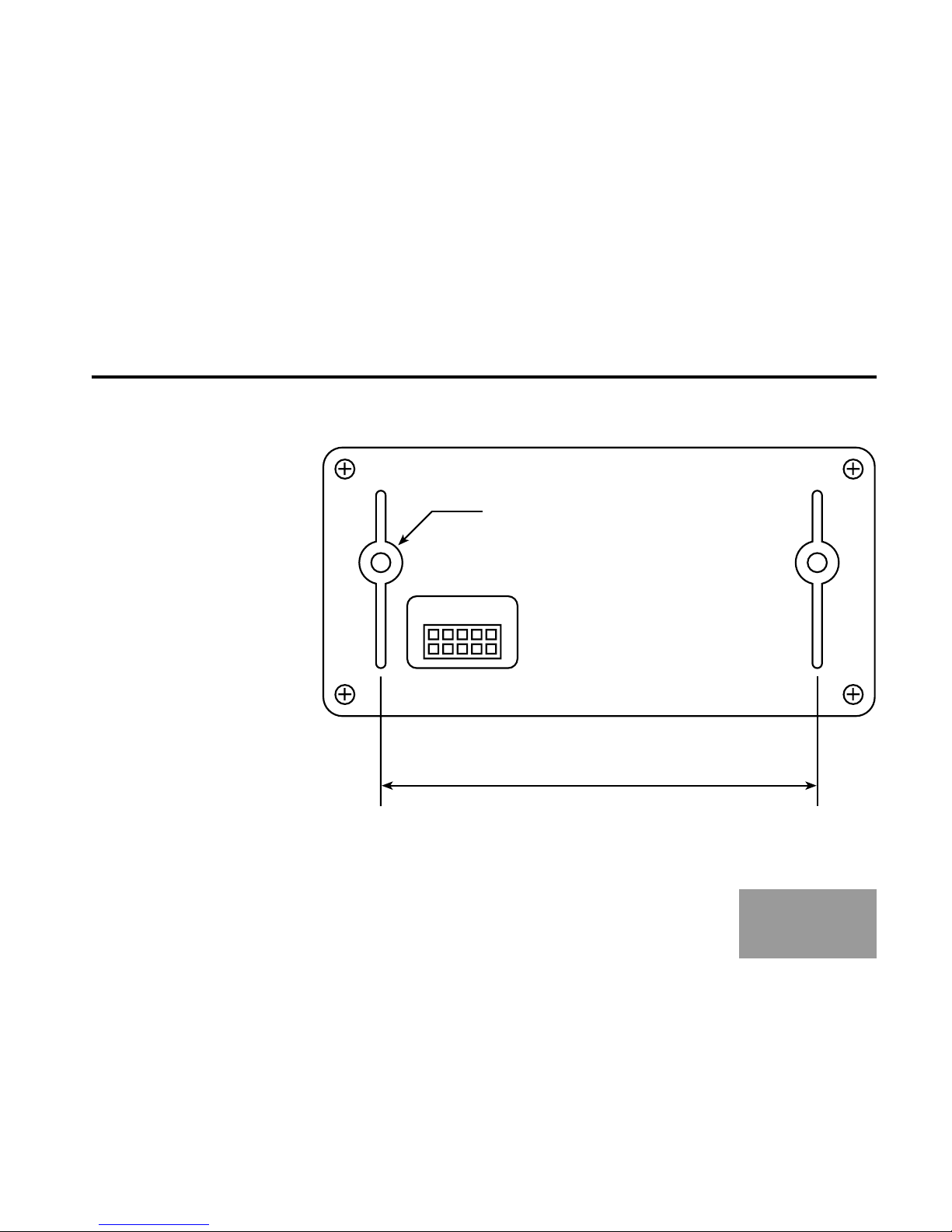
To simplify attachment to your vehicle, the
device has two metal bosses molded into
the back part of the case. These accept
standard M4 bolts. When mounting, also
remember to leave space behind the unit for
its electrical connector.
Before You Start
Installation of the TC100 requires a moder-
ate level of mechanical ability and a basic
understanding of electrical systems. If you
do not have experience in these areas, we
recommend that you employ the services of
a qualied automotive technician.
If you do decide to install the unit yourself,
please ensure that you read all the instruc-
tions carefully before starting.
Monit Limited accepts no liabil-
ity for any damage to property
or persons, whether direct or
consequential, as a result of
the incorrect installation of the
product.
Warning

A-3
Installation
Mounting
Boss Positions
(not to scale)

Installation
A-4
Electrical Connections
All electrical connections to the device are
made through a single connector located
on the back of the unit. Included with your
TC100 is a pre-wired loom that attaches to
this connector, and provides colour coded
wires for each signal. The functions associ-
ated with each of the wires on this loom are
shown in the table on the right.
In its most basic conguration, the unit re-
quire only three wires to be attached: the
two connections to the battery, and a vehicle
speed signal. More complex setups might
also use one or more of the auxiliary inputs,
or the regulated 5V power supply for active
type speed sensors. Whether these are re-
quired or not will depend on your vehicle
type and setup preferences.
Colour Description
Red Battery +12V
Black Battery Ground
White Auxiliary A Input
Brown Auxiliary B Input
Orange Sensor +5V Supply
Blue Speed Signal Input
Yellow Sensor Ground
When connecting the unit up, ensure that
any unused wires on the loom cannot short
against each other or the vehicle’s chassis.

A-5
Installation
Power Supply
The device should be connected to the vehi-
cle’s battery through a 2A fuse as shown on
the right. Make sure it is attached to a point
in the system where power is always avail-
able, even when the ignition is turned off. An
external power switch is not required.
Auxiliary Inputs
The unit includes two auxiliary inputs that
can provide short-cuts to common tasks,
such as resetting the counters or control-
ling the stop-watch. If used, these should
be connected to user supplied switches as
shown on the right. For more information on
the setup and operation of this feature, see
page C-4.

Installation
A-6
Vehicle Speed Signal
The most important input to the rally com-
puter is the vehicle’s speed signal. If your
vehicle has a factory tted speed sensor,
chances are you will be able to connect this
directly to the unit. Otherwise, you will have
to purchase and install an after-market sen-
sor solution. For more information, contact
a monit sales representative to discuss the
options for your vehicle.
The type of speed signal accepted by the de-
vice is a digital pulse that switches between
0-5V or 0-12V and with a frequency of less
than 1kHz. Sensors that produce this type of
signal can be connected directly to the unit’s
blue wire. For sensors that require external
power, a regulated 5V power source is avail-
able from the orange coloured wire.
Tidying Up
Before you power the unit up for the rst
time, check that all your electrical connec-
tions are correct and securely made. Also
make sure that any exposed wires in the
circuit are covered with insulation tape or
heat-shrink.

B-1
Getting Started
Basic setup and operating information to
get you up and running quickly.

Getting Started
B-2
Overview
If you have ever used a mobile phone or
MP3 player device, you should nd the
TC100’s user interface quite familiar. But if
not don’t despair—the TC100 has been de-
signed with you in mind. Just take the time
to read through this section and discover for
yourself how easy to use it is.
Turning On & Off
The device enters a low power sleep state
after ve minutes of inactivity. To start the
unit up again, press any of the buttons or
begin driving the vehicle.
User Interface Basics
The device’s user interface consists of the
liquid crystal display and the four buttons
that surround it. Like many modern devices,
these buttons do not have dedicated func-
tions assigned to them. Instead, the tasks
they perform change depending on where in
the menu system you are. The task that is
currently assigned to a particular button is
shown on the screen by a text label, as can
be seen below. The four labels are inside the
dark bars on the right and left edges of the
screen.
Remember to always read these labels,
as they are there to guide you through the
menu system.

Getting Started
B-3
Telemetry Screen
The rst screen to appear on the display
when you power the device up is the Telem-
etry Screen. It can be seen in the image on
the right. This screen displays the vehicle’s
distance, speed and timing information and,
as you might expect, is the one you will use
the majority of the time during a rally.
Functionally, the screen is split vertically into
two display areas. The rst of these, the top
half, always contains the Interval Distance
counter. This counter is typically used dur-
ing a rally to measure the distance between
junctions, landmarks and other road-book
instructions. To reset the counter, press the
top-right button labelled CLR.
Telemetry Screen (kms)
The bottom half of the screen works differ-
ently. Rather than being dedicated to one
particular function, the space can be used
to display a Total Distance counter, the vehi-
cle’s Current Speed, Maximum Speed, or a
stop-watch. Press the MODE button to cycle
through each of these functions.

Getting Started
B-4
The rst image on the left shows the Total
Distance counter. This works independently
from the Interval counter and is typically
used to measure the distance since the start
of a stage, day or event. When selected, it
can be cleared by pressing the bottom-right
CLR button for one second.
The second and third images show the
Current and Maximum Speed readouts re-
spectively. When the latter is visible, it can
be cleared by pressing the bottom-right CLR
button for one second.
The nal image shows the built in stop-
watch. When visible, this can be started and
stopped by pressing the bottom-right button.
It can be reset by holding down the same
button for one second.

Getting Started
B-5
Menu System
Using the menu system you can quickly
change settings and access the device’s
more advanced features. To exit the Telem-
etry Screen and enter the menu system,
press the MENU button.
The main menu consists of a set of six icon,
one for each of the six sub-menu catego-
ries. To cycle through these use the LEFT or
RIGHT buttons. When the desired category
is highlighted, press the OK button to bring
up the associated sub-menu. These can
then be navigated in a similar way.
To return to the Telemetry Screen at any
time, press the top-left BACK button.

Getting Started
B-6
Calibration
Once you have nished installation of the
rally computer, you will need to calibrate it to
ensure it works accurately. Fortunately this
is very easy to do. With the unit powered
up, navigate to the Calibration sub-menu
and select the item called ‘Calibrate’. This
will start a special calibration wizard that will
guide you through each step of the process
with clear on-screen instructions.
All you need to perform the calibration is a
section of road with an accurately known
distance. In some areas you may be able to
use special road markings, otherwise your
vehicle’s factory odometer may sufce. For
best results choose any distance of between
1 and 99km. When the process is complet-
ed, the unit will retain its calibration, even if
power is removed.

Getting Started
B-7
When the wizard is started, the rst screen
to appear will instruct you to drive to the start
of your known distance. Press the OK but-
ton when this has been reached. Continue
to drive until you are at the end of the known
distance, then press OK again. A data entry
screen will now appear prompting you to en-
ter the distance you have travelled.
The data entry screen (shown right) works
by allowing you to enter each of the value’s
digits individually. The digit that is currently
being modied is shown highlighted and
can be adjusted using the UP and DOWN
buttons. Once you have set it to the desired
value, press the NEXT button to move the
highlight to the adjacent digit. When all the
digits have been entered, the NEXT button
will change to say SET. Press this to con-
rm the value and complete the calibration
process.

Getting Started
B-8
Changing the Display Resolution
The TC100’s distance counters usually
show a resolution of ten metres, which is
suitable for most motorsport applications. If,
however, you desire a higher level of accu-
racy (e.g. for road survey work), the display
resolution can be increased to one metre. To
do this, navigate to the Settings sub-menu
and select the ‘Resolution’ item. This will
toggle between the two available levels.
Setting the Counting Direction
The unit’s distance counters can be cong-
ured to count either up or down. To change
the direction, navigate to the Settings sub-
menu and select the ‘Counting’ item. This will
toggle between the two available modes.
Dimming the Backlight
The TC100 has a very bright white LED
backlight. In daytime and low light condi-
tions this substantially improves the visibility
of the display. However, at night, this intense
light may be distracting. To reduce its inten-
sity hold down the MENU button in the Te-
lemetry Screen for one second. Repeating
this will return it to full brightness.
Changing the Display Units
The TC100 works in either miles or kilome-
tres. To change the units that are used, navi-
gate to the Settings sub-menu and select
the ‘Display Units’ item. Calibration values,
stored maximum speed, and distance coun-
ter values are automatically converted when
this setting is changed.

C-1
Advanced Features
Detailed information about some of the
TC100’s more powerful features.

Advanced Features
C-2
100kph (60mph) Sprint Timer
The built in sprint timer can be used to accu-
rately measure your vehicle’s 0-100kph (0-
60mph) times. It can be accessed from the
Performance sub-menu. To use the timer,
bring the vehicle to a halt and follow the on-
screen instructions to arm the system. Once
this is done, the timer will start automatically
when it detects movement, so simply begin
accelerating when ready. Upon reaching
100kph (60mph), the timer will stop and dis-
play the acquired sprint time.
Other manuals for TC100
1
Table of contents
Other Monit Rally Automobile Accessories manuals