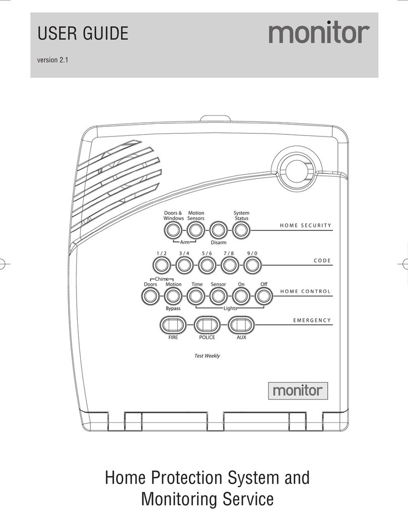
Monitor TAD-260 Parts list manual

Monitor
Installation Instructions
and
Operating Manual


Monitor
Installation Instructions and
Operating Manual
Applicable to Firmware version 1.0 to 5.0


1
Help Symbols
Throughout the instructions symbols have been included to quickly
identify the nature of the information. Detailed below is the key and
brief explanation to the symbols used.
Warning - an indication of the potential for equipment
damage or personal injury.
Information - instruction on how to complete a task or set
up.
Followed correctly the system will operate correctly.
Stop and check - This is used where not following the
instructions will result in damage or failure.
Information in this document is subject to change without notice
© 2011 Accordant Marketing UK Ltd
Reproduction in any manner whatsoever without the written permission of
Accordant Marketing UK Ltd. is strictly forbidden.
May 2011 Doc # MM001 version 1.5

2
Contents
Section
Number
Section
Page
Help Symbols
1
Contents
2
About Monitor
5
Installation Instructions
10
1
Positioning
10
2
Mount Control Unit
12
3
Mount GSM/GPS Antenna
13
4
Wiring
13
Channel Default Configuration
14
Power Supply
15
Siren
16
Strobe
16
Beeper
17
Remote Switching
17
External LED
18
Microphone
18
Speaker
18
5
Install Sensors
20
PIR
21
Beam Break
22
Microwave
23
Magnetic Contact
24
Security Loop
25
Shore Power
26
Externally Powered Devices
28
NMEA Connection
29
Tamper Connections
29
Wireless Transmitter
30
6
Install SIM Card
32
7
Configure Unit
33

3
Section
Number
Section
Page
Initialise Monitor System
33
Set up Phones
35
Changing Password
37
Set Up Channels
37
Set Up Key Fobs
37
Configure Auto Status Reporting
38
Configure Auto Call
38
Config Battery Low Voltage Warning
39
Set up SIM Credit Check Function
40
8
Commissioning
41
Channel Alignment Test Mode
41
Test Siren/Beeper/Strobe
41
Microwave Sensor Set Up
42
Beam Break Sensor Set Up
43
General Sensor Checks
43
9
Apply Warning Label
44
10
Advanced Set Up
45
Channel Configuration
45
Channel Configuration Table
46
Sleep Safe (Part Arm) Mode Set Up
48
Configure Dead Time
48
Name the System
49
Configure Overspeed Alarm
49
Reset Control Unit
49
Reboot Control Unit
50
Operating Instructions
51
11
Operation
51
Query System Status
51
Query Channel Status
51
Query NMEA Equipment Status
52
Query Remaining SIM Credit
52
Arm/Disarm System
52
RF Key Fob Operation
53
Control Output Switch
53
Reboot Control Unit
54
LED Status
54
GPS Operation
55

4
Section
Number
Section
Page
GeoFence Operation
56
Microphone Operation
57
Speaker Operation
57
12
Default Settings
58
13
Electrical Specifications
59
14
Wiring Diagrams
60
Main Control Unit
60
Connecting Shore Power Sensor
63
Connecting Switching Relay
64
Connecting Switching Relay (2 Way)
65
Connecting Protecting Relay
66
15
Support
67
16
Firmware Updates
68
17
Text Commands
70

5
About Monitor
General
Monitor is a comprehensive marine monitoring and security system with
GSM remote communication (via your mobile phone). Depending on the
model it protects against boat intrusion, boat movement (using built in
GPS) and monitors other boat systems.
When the boat alarm is triggered you are informed by text message and
an onboard siren and/or strobe is set off. When you want to know what is
happening on board you interrogate it via text messaging.
The standard model is supplied suitable for use on a 12v system, however
24v systems are available by special order.
Boat Alarm
Using an array of intrusion detectors Monitor will sound an alarm
(including a strobe light) on board the boat and at the same time inform
up to 10 mobile phones of the intrusion. If the boat is taken or moves
outside of a user defined area, up to 10 mobiles are informed (not Monitor I).
A Sleep Safe/Part Arm feature allows for sleeping on board whilst
maintaining protection from outside sensors (not Monitor I)
Boat Monitoring
Monitor will also sense and inform when the battery levels fall, bilge
levels rise*1, the smoke alarm is activated*1and so on. This monitoring is
always on whether the boat alarm is set or not. You can listen via phone
to what is happening on board*1and speak to those on board*1. If you
are slipping an anchor then it will inform you when a user set distance is
breeched and can be configured to inform if a user definable speed is
breeched or if you have NMEA equipment on board you can request a
report of their outputs*2(Monitor III only)
*1- when fitted with the correct accessory
*2- limited to certain outputs

6
Boat Control
All Monitor versions can be configured to switch one primary circuit by
the key fob and text message (we suggest your lights for safely boarding
when arriving back in the dark). Up to a further 8 boat circuits*3(Monitor III)
or 4 boat circuits (Monitor II) be remotely switched (by text only) even when
you are miles from the boat.
*3 – 5 circuits (up to 8 if Siren, Strobe & Beeper are not required), requires suitable relays
Boat Tracking (via GPS)
Monitor comes with integrated GPS. This can be used for locating your
boats position whether on the sea or trailer (all models). In addition a
GeoFence can be set to provide a movement alarm (see ‘Boat Alarm’
above), an anchor alarm, provide position, speed and heading information
as well as a user definable ‘over-speed’ alarm (not Monitor I).
Not just a modified car or house alarm
Monitor was designed through consultation with boat owners, marine
and security experts and builds on the previous Nautilarm platform.
It is a high quality unit designed for use in the challenging environment
and conditions found at sea, in particularly the Rugged version is aimed at
open or semi open craft.
Monitor has been designed with extremely low power consumption to
avoid battery discharge problems. It has built in boat battery monitoring
capable of monitoring up to 3 battery banks (Monitor II & III –Monitor I only 1 bank)
which alerts at a user definable voltage and its own internal back up
battery should the main power be cut or fail.
Accessories
There are a number of options to tailor the system to your requirements.

7
Designed and built in the UK
Monitor was designed and is fully assembled in the UK. The components
are all of high grade and designed for use in harsh environments. The
GSM units are made from components approved by mobile phone
network providers.
What you need
All of the Monitor versions can be supplied as a standard kit, or tailored to
suit your needs. These kits are supplied with instructions should the
preference be to carry out a DIY installation. With the exception of any
holes required to pass through internal panels or trim etc. no specialist
tools are required. The fixing kit is supplied with a small flat blade
screwdriver for connecting the terminations into the control panel. Other
than this it is recommended that a suitably sized and correct format
screwdrivers and side cutters are all that is required.
Help in deciding configuration or with installation questions is available
from
Precision Navigation
+44(0)1473 327813
info@precisionnavigation.co.uk
Assistance is normally available during normal office hours (09:00 to
17:30 Mon to Fri). If no one is available at the time of your call a Voice
Mail can be left and the call will be answered within 1 working day. E-
mails will be responded to within the same time frame.
Specification
For a full specification please see the specifications section towards the
rear of this booklet.

8
Compliance
R&TTE DECLARATION OF CONFORMITY
This is to certify that “Monitor” Systems (component products; Control
Unit TAD-260, RF Transmitter TAD-214-W300) conform with the following
standard(s) or other normative document(s), ETSI EN 301 511, EN 301 489-
7, EN 60950-1, following the provisions of R&TTE Directive 1999/5/EC,
when used with the manufacturer-supplied GSM antenna.
ROHS COMPLIANCE DECLARATION
This is to certify that, to the best of our knowledge based on the
information provided to us by our suppliers, “Monitor” Systems have been
designed and manufactured to be in full compliance with the European
Union’s (EU) Restriction on use of Hazardous Substances (RoHS) Directive
2002/95/EC.
FCC COMPLIANCE DECLARATION
“Monitor” Systems (component product; Control Unit TAD-260) contains
FCCID: MIVGSM0308. This is to certify that this device conforms with part
15 of the FCC rules. Operation is subject to the following two conditions:
(1) This device may not cause harmful interference and (2) This device
must accept any interference received, including interference that may
cause undesired operation.
Specifications may change without notice. The Monitor products are
produced in the UK by TAD Electronics.
“Monitor” systems are not safety critical products. They also cannot stop or
prevent a burglary. However, a correctly installed, set up and maintained system,
when armed will sound a siren and trigger a strobe (if fitted) and notify by SMS
message if any of the zones are triggered. The prime intent is to discourage a
would-be burglar. The manufacturers of “Monitor” systems will not be responsible
for the failure of the alarm in preventing a burglary or any resulting/consequential
damage or loss.

9
Warranty
Without affecting your statutory rights, Monitor products, when fitted correctly
are warranted to be free of manufacturing defects for a period of 1 year from date
of purchase or if fitted by a recognised dealer from the registered date of fitting.
Should a component fail due to a manufacturing defect during this time, then a
replacement component will be supplied following return and inspection of the
failed item, every effort will be made to complete this in a timely manner. Damage
caused by incorrect installation and or operation will render this warranty void.
The manufacturers of “Monitor” products will not be liable for any
removal/reinstallation costs or any consequential costs whatsoever.

10
Installation Instructions
1. Positioning
Before installation careful consideration needs to be given as to the
location of the control box and sensors. Every type of boat will be
different, as will each owners preferences; there is no ‘one-fits-all’
recommendation, however if the following considerations and guidance
are followed the best operating condition will be achieved.
a. Discreet Location, to protect it from wilful damage and
disablement the control box is manufactured void of any external
logos or information which identifies it as an alarm, to further
protect it a discreet location should be selected that also allows
sufficient access to fit and maintain the unit.
b. Vicinity to power source, antenna and sensors, the
location should also be such that the routing of cables can be
minimised and when finished discreet. In addition an absolute must
be the location of the antenna (see below) and the consequential
cable route from the control unit. It is essential that a fused (5A)
12V supply that is not switched by a Master Switch and ‘therefore
permanently-on’ is used. NB 24V configurations are available.
c. Antenna location, there are different types of antenna
available, depending on hull material and personal choice.
Experience has taught us that it is impossible to say the maximum
thickness of fibreglass that the standard self adhesive antenna will
comfortably operate through, in some cases they have performed
well through 25mm, in other situations 15mm has proven to limit
the operation. One thing is clear, if the structure is of metallic
construction the antenna will not operate effectively through it. It is
essential that a ‘Through Deck’ antenna be used on metallic or thick
fibreglass structures. For fibreglass under 20-25mm thick the
standard self adhesive antenna is better suited. In all cases test the
operation of the antenna before any permanent fixings are made.
Antenna are supplied with integral 5m leads, if this is insufficient 5m
extension leads are available.

11
d. Sensor location. Beam breaks are IP69 rated and can (but
don’t have to) be positioned in outside/wet environments, these are
best positioned to detect any ‘prior to entry’ movement thus
preventing damage to locks, doors etc., a simple cover will prevent
accidental triggering by birds. PIR sensors should be positioned so
they cover areas of possible entry whilst avoiding areas of flashing
sunlight which can cause false sensing. Magnetic Contact sensors
can be fitted to opening hatches and doors, consider the routing of
cable to the contacts. When using wireless sensors, it is
recommended that they are mounted within 20m of the alarm
control box and that there are no metal bulkheads between it and
the control box
e. Siren, external LED & external beeper location, to have the
maximum effect in alerting others around that there is an intruder
the siren needs to be positioned so that it is not muted by enclosure
or other sound barriers, positioned inside an external vent allows
good external sound travel and maximum discomfort to any intruder
whilst restricting access thus preventing disablement of the siren.
A second siren can be fitted (if our high output sirens are used) to
sound inside and out. If other sirens are used they must not draw
more than 1A collectively this would overload and damage the
system, use of a relay would enable the operation of more powerful
sirens. The external LED (used to indicate GSM & GPS Signal) should
be positioned so that it can be easily monitored without the
continuous flashing becoming an annoyance. The external beeper
should be positioned so as it can be heard whilst boarding and
alighting the boat but does not have to be in line of sight so can be
discreetly mounted.
f. Microphone & Speaker location, will, depending on their
purpose, require mounting discreetly or conveniently.
Consideration should be given to protection from the elements,
back ground noise, intended purpose and ease of use. The system is
not primarily intended to be used as a phone it cannot be used to
dial out (only receive calls), its primary purpose being to listen to on
board activity to confirm if someone is legitimately on board and
inform anyone on board that you are aware of their presence. When
the system is called if a speaker is fitted there will be three rings and
the call will automatically be answered.

12
2. - Mount Control Unit
2.1. - The Monitor I, II & III Control Unit standard enclosure (not shown) is not
a water resistant case so should be mounted in a dry environment;
Monitor Rugged enclosure (shown) is designed to cope with wet boats but
the driest position is preferable, the Rugged enclosure should be mounted
with the glands at the bottom
to ensure maximum water
resistance. For all versions
ensure that enough space is left
around the unit for cable
routeing and future removal and
refitting of the control box lid for
maintenance tasks.
2.2. - The design of the Rugged
control unit enclosure is such
that it can be screwed to the
mounting area without puncturing the ‘sealed’ part of the unit. The
fixing holes are in each of the 4 corners adjacent to the lid securing
threaded holes (see red arrows on adjacent picture).
2.3. - If fitted to a ‘wet’ area, as additional precaution the Rugged
Control Unit enclosure cable glands should be sealed with a silicon sealant
after the unit has been cabled and tested. Whether sealed or not the
glands should be tightened around the cables. If sealant is going to be used
this is best applied to fill the ‘gaps’ around the cables, the glands should be
tightened just enough to extrude excess sealant then left for the sealant to
set, after which final tightening of the gland will ensure maximum water
resistance.
2.4. –The standard and Rugged enclosure has a small RF antenna that
screws into the PCB through the case, to ensure integrity of the Rugged
enclosure the antenna should be sealed (with a silicon sealant) on
completion of instalation.

13
3. - Mount GSM/GPS Antenna
3.1. - Monitor Systems are usually supplied with a self adhesive internal
antenna It is essential that the antenna is
correctly mounted (the adhesive pad is
designed to allow mounting on either side),
the flat surface must be towards the sky
and clear of any large metal objects (the
ridge (see red arrow) is the back/underside).
3.2. - The GPS signal will not penetrate
metal or thick fibreglass (typically it can cope with up to 15-25 mm of
fibreglass but operation must be checked prior to any permanent
fixing).
3.3. - If the system is being installed into a metal boat or under thick
fibreglass the external ‘Through Deck’ antenna must be used. The antenna
can be painted.
4 - Wiring
4.1. - A full wiring diagram has been supplied to the rear of this manual.
Please refer to it when wiring the Monitor Systems.
4.2. - The Monitor System Channels can be set up to operate in several
formats (e.g. as an alarm channel, a monitoring channel or a switching
channel), not all channels can do all functions. The system has a default
configuration and in most situations connecting the ancillaries to a
compatible channel is all that will be required. Table 4.2.1 shows the
default configuration. The wiring described in this section is based on a
default configuration, where options are available they will be covered
later in Advanced Set Up section.

14
Table 4.2.1
Connector
Channel Number
Default Function
A
0V (Ground)
Non Configurable
B
Power feed
Non Configurable
C
Battery 2 (not Mon I)
Non Configurable
D
Battery 3 (not Mon I)
Non Configurable
E
Temperature (not Mon I or II)
Non Configurable
F
LED+
Non Configurable
G
LED-
Non Configurable
H
Speaker +
Non Configurable
I
Speaker -
Non Configurable
J
Channel 1
Siren
K
Channel 2
Strobe
L
Channel 3
Bleeper
M
Channel 4
RF Switch
N
Channel 5
Switch II (not Mon I)
O
Channel 6
Switch III (not Mon I)
P
Channel 7
Switch IV (not Mon I)
Q
Channel 8
Switch NMEA (not Mon I or II)
R
Channel 9
Alarm (CH) I
S
Channel 10
Alarm (CH)II
T
Channel 11
Alarm (CH)III
U
Channel 12
Alarm (CH)IV
V
Channel 13
Monitor (CH) I
W
Channel 14
Monitor (CH) II
X
NMEA data (not Mon I or II)
Non Configurable
Channels 15-24
Wireless Channels
4.2.2. - Terminals A, B, C, D, E, F, G, H, I and X have fixed configurations and
can NOT be re-configured.
4.2.3. - As examples using default settings: -
4.2.3.1. - PIRs, Microwave Sensors, Magnetic Contacts or Security Loops
can be connected to any of channels 9, 10, 11 or 12 without any re-
configuration of the channel.
4.2.3.2. - The switched circuit to be controlled by the Key Fob & Text
Message should be connected to channel 4.
4.2.3.3. - Any other switched circuits (Not applicable to Monitor I) to be
controlled by text Message only should be connected to channels 5, 6 or
7.

15
4.2.3.4. - Any monitoring sensors such as bilge level, smoke detector,
Shore Power can be connected to either channels 13 or 14.
4.3. - It is essential that the correct cabling is used; oversized could result
in problems in terminations, undersize may not carry the load or result in
signal loss. For power and sensors requiring only 2 wires we recommend
the use of 2core 0.5mm2cable, for sensors requiring more than 2 wires we
recommend the use of standard 4 core alarm cable.
4.4. - The GSM and GPS antenna connectors on the Monitor Control Unit
standard enclosures are located on the external left hand side of the case;
Monitor Rugged enclosure has them mounted inside the case. The
connectors are polarised so they cannot be incorrectly fitted. The Wireless
RF antenna is externally mounted below the GSM/GPS connectors on
standard enclosures, and on the top of the Rugged enclosure.
4.5. - Power Supply
4.5.1. - Monitor systems are available in 12V (a 24V version is available at a
supplement). Ensure that you are using the correct version for the
supply voltage in use.
4.5.2. - The supply should be fused at 5A. If a Monitor kit has been
purchased, a wiring loom with an inline fuse folder will have been
supplied. The fuse should be mounted as near to the battery as possible so
that the whole cable run is protected.
The power must not be switched on during installation or whilst any
connection/disconnection is made (This includes disconnection of the
internal Battery).
The Power must not be switched on during fitting or removal of the
SIM card (This includes disconnection of the internal Battery).
4.5.3. - Connect: -
0V / GROUND / BLACK wire to terminal A (SUPPLY-).
+12V / RED wire to terminal B (SUPPLY+).

16
4.6. - Siren
4.6.1. - The siren(s) should draw no more than
1A (if using a large or multiple siren(s) results in a
load of more than 1A it is recommended to use a
Relay to operate the siren(s)). The siren will
sound for 3 minutes when the alarm is
triggered.
4.6.2. - Connect: -
POSITIVE / RED wire to one of the PowerOut terminals.
NEGATIVE / BLACK wire to terminal J (Channel 1).
4.7. - Strobe
4.7.1. - The strobe(s) should draw no more than
1A (if using a large or multiple strobe(s) results in a
load of more than 1A it is recommended to use a
Relay to operate the strobe(s)). The strobe will
flash when the unit is triggered and will keep
flashing until the system is disarmed.
4.7.2. - Connect: -
POSITIVE / RED wire to one of the PowerOut terminals.
NEGATIVE / BLACK wire to terminal K (Channel 2).
This manual suits for next models
1
Table of contents
Other Monitor Security System manuals
Popular Security System manuals by other brands

DSC
DSC Impassa WT4989 operating instructions

NetScreen Technologies
NetScreen Technologies ISG 2000 Field Upgrade Guide

Denver
Denver HSA-120 Installation and user manual

DPS Telecom
DPS Telecom D-PC-293-10A user manual

Safeguard Supply
Safeguard Supply ERA-DSRXPG owner's manual

Flamingo
Flamingo HA31S user manual