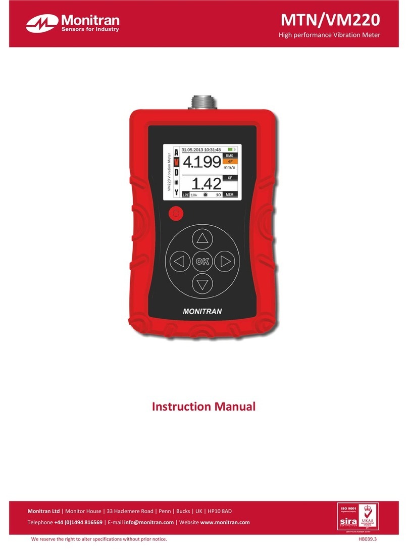
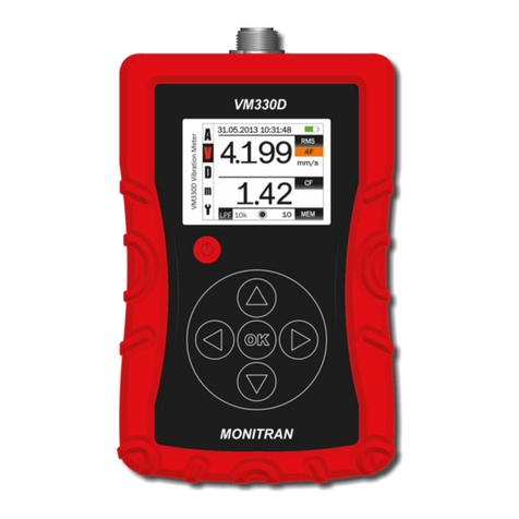
Monitran MTN User manual

©MonitranLimited2013•
HB039.1
•
07/2013
^fll
Monitran
Sensorsfor
Industry
MTN/VM220
High
performanceVibrationMeter
ft
InstructionManual
MonitranltdI Monitor
House
I
33
Hailemere
Road
I
Penn
I Bucks| UK1 HP108AD
Telephone
•44(0)1494116569
|
E-mail
lnfogmonitran.com| Websitewww.monitran.com

0.
Contents
1.
Introduction1
2.
Precautions1
3.
Equipmentdetails1
4.
Preparationforuse2
5.
Buttons3
6.
Display3
7.
Connections4
8.
Batterystatus4
9.
Chargingtheunit4
10.
Connecting
sensor
5
11.
Measurementmodes6
12.
Calculationmodes6
13.
Memoryrecallmode7
14.
Settingsmenu8
15.
Settingtheclock8
16.
Settingunits8
17.
Settinglowpassfilter9
18.
SettingISO10816group9
19.
Clearingmemories9
20.
ISO1081610
21.
Physical11
22.
Specifications12
23.
Troubleshooting14
24.
Aftersalessupport14
A.Mainoperations15
B.
Conversions
andformulae16
1.
Introduction
I
The
MTN/VM220
VibrationMeterisa rechargeable,portableinstrumentdesignedtooperatewitha constantcurrent
typeaccelerometertoprovideaccuratevibrationmeasurements.
ConformingtoISO10816-3/7,
MTN/VM220
willdisplayRMS,peak,peak-peak,crest factorandbearingconditiononits
pin-sharpcolourscreen.Upto100time-stampedreadingscanbestoredtonon-volatilememory.
The
MTN/VM220
isaninvaluabletrouble-shootingtoolforinstrumentationengineersfamiliarwiththeproblemsof
plant
vibrationmonitoring,providinganinstantreadoutoftheconditionofbearingsandrotatingparts.
2.
Precautions
•
Only
usetheunitasdirectedinthismanual.
•
Protecttheunitfromshocksandextremesoftemperature,humidityandharshenvironments
(such
ashighsalt).
•
Use onlya softcleancloth.Donotusesolventsorharshcleaningagents.
•
Theunitcontainsno
user
serviceableparts.Donotattempttodisassembleorrepairtheunit,asthiswillinvalidate
your
warranty.
•
Toensurecontinuedperformance,
have
theunitcheckedand
serviced
atregularintervals.
3.
EquipmentDetails
Purchase
date:
Vibrationmeterserialnumber:
Cable
serialnumber:
Sensor
serialnumber:
Softwareversion:
1

4.
Preparationforuse
Carefullyremovetheinstrumentfromthetransitpackagingandensureallaccessoriessuppliedagreewiththedelivery
note.
Visuallyinspectfortransitdamage.
MTN/BT004
Worldwideadaptor
MTN/CA477
USBA to
mini
USB
chargercable
MTN/CA476
Coiled
sensor
cable
MTN/2100-X
Probe MTN/PS002
4"
X"
28UNF
Spike
MTN/MM001
Magnet
Charger
Adapters
2
5.
Buttons
J
Date/time
Measurementmode-
vlemoryrecallmode-
Settingsmode
•
m
4.199 mm/s
-
14?
||||iok|
e | io
_
MEM
ConnectionCurrent
Lowpass
filter
statusmemoryslot
•Calculationmode
•
ISOWRIfi
status
-ISO10816class
•Vibrationunits
3

7.
Connections
Sensorcable
connector
Headphone
jack
Theheadphonejackwillaccepta 3.5mmstereojackplug.Headphones(notincluded)maybeusedtolistentothevibration
directly.A dataloggercanalsobeconnectedtotheheadphonejack.
Toavoidhearingdamage,useofheadphoneswithaninlinevolumeadjustmentisrecommended.
Ensure
thevolumeisturned
downbeforeconnecting
your
headphones.Afterplacingheadphonesin
your
ears,graduallyturnupthevolumeuntilyoureacha
comfortable
listeninglevel.Donotuseheadphoneswhenit'sunsafetodoso- whileoperatinga vehicle,orduringanyactivityorin
anenvironmentwhere
your
full
attentionto
your
surroundingsisrequired.
8.
Batterystatus
Normaloperation
100%
50%
25%
10%
Charging
Themeterwillautomaticallyturn-offafter15minutesofinactivity(5minutesif
sensor
notconnected).
9.
Chargingtheunit
Thesuppliedmulti-voltagechargercomeswith4 adaptorsandissuitableforuseworldwide.
Connect
thecorrectadaptorfor
your
region,plugintomainsandconnecttheminiUSBtotheMTN/VM220.
Theunitshouldreach
full
chargewithin4 hours.Thebatterystatusiconwillindicatechargingisinprogress(see6.
Display & 8. Battery
status).
Whenthebatteryislevelislow,a warningscreen(seeleft)willdisplayfor5
secondsandtheunitwillpoweroff.
Connect
charger
10.
Connecting
sensor
J
The
sensor
andcablecanbeconnected/disconnectedatany
time.
Once
fullycharged,brieflypressthepowerbutton9 toswitchtheuniton.
Connect
eitherendofthecableto
the
unitbyrotatingtheconnector
to
alignthekey.
Once
inthecorrectposition,the
connectorwilldropintothesocket
andtheknurlcanbetightenedto
holdtheconnectorinplace.Do
not
overtighten.
Repeatthisprocesstoconnectthe
sensor
totheotherendofthecable.
Notes:
Theconnectionstatusicon(see6. Display) willchangeaccordingly.
Attachspikeormagnet,ifrequired.
Noconnection
Cable
connected
Sensor
connected
5

11.
Measurementmodes
i&
Press
buttonsWWtoswitchbetweenmeasurementmodes.
Thecurrentmode
will
behighlighted.
Unitsforeach measurementmodecanbeset(see16. Setting units)
MODE
UNITS
A Accelerationmode
g
m/s2
1
Velocity
mode
mm/s
in/s
D Displacementmode urn
mils
1
Memoryrecallmode(see13. Memory recall mode)
V Settings(see14. Settings menu)
12.
Calculationmodes
Whentheunitisinoneofthemeasurementmodes(acceleration,velocity,displacement),
press
buttonsWWto
switchbetweenRMS,peak-peakand
O-peak
displays.Anadditionalbearingdisplayisavailableinbothaccelerationand
velocitymeasurementmodes.
Display Calculationmode
RMS Rootmeansquare
PK-PK
Peaktopeak
0-PK
Zero
topeak
B Bearing
Press
@ tostorethedisplayedvalueinthecurrentmemoryslot.Thecurrentmemorynumber
will
automaticallymove
to
thenextslot.
•
Current
time
•
Current
date
•
Measurementmode
•
Calculationmode
•
Crest
factorvalue
•
Vibrationvalue& units
/
[x\+ x\+ + K) _ . >U
X= , / -
Crest
Factor
=
Vn x,m
where:
*™ = RMS value
*
= sample
n
= number of
samples
The
Crest
Factor
isequaltothepeakamplitudeofa waveformdividedbytheRMSvalue.Thepurposeofthe
crestfactorcalculationisto
give
ananalysta quickideaofhowmuchimpactingisoccurringina waveform.
Impacting
isoftenassociatedwithrollerbearingwear,cavitationand
gear
toothwear.
6
•
13.
Memoryrecallmode
1
Using
buttonsWW,selectmemoryrecallmode.
Press
buttonsWWtonavigatethroughmemoryslots
Whenreturningtothemeasurementmode,theselectedmemoryslot
will
bethecurrentmemoryslotforthenext
store.
It
ispossibletoquicklyclearallmemoryslots(see18. Clearing
memories).
Memory
slot
measurement
morle
Vlemory
recall
mode
•
Memory
slot
lowpass
filter
31.05.201310:31:48
m
4.199
•
"142
mm/s
Measurement
mode
•
V
D
Date/time
I
31.05.201310:31:48
4.199
RMS
Calculation
mode
mm/s
1
Vibration
units
Y
1.42
10k
lowpass
filter
Current
memory
slot
There
are100memoryslotsin
total.
Thebluefieldsshowninthe
above
figureare
saved
intomemory
ProvidedtheunitisreturnedtoMonitranforservice,thememories
will
remainintact,
even
afterbatteryreplacement
andcalibration(see24. After
Sales
Support)
7

14.
Settingsmenu
•
Using
buttons
WW,
select
1.
•
Press
button
® to
entersettingsmenu.
•
Use
buttons
®W©Wto
navigateand
press
© to
selectoption.
•
Use
button
W to
navigateback
to
themainmenu.
31.05.2013
10:31:48
31.05.201310:31:48
•
FILTER
•
IS010816
15.
Settingtheclock
•
Enter
settingsmenu
(see
14.Settings menu)
•
Press
button
®
twice
to
highlight
CLOCK
and
press
© to
enterclockmode.
•
Use
buttons
WWtosetDAY/MONTH/YEAR/HOUR/MINUTE
settings.
•
Press
buttons
to
change between
DAY/MONTH/YEAR/HOUR/MINUTE.
•
Press
© atany
time
to
save
andreturn
to
settingsmenu.
16.
Settingunits
31.05.2013
10:31:48
FILTER
•
IS010816
31.05.201310:31:48
•
31
05
2013
10
31
•
Enter
settingsmenu
(see
14. Settings menu)
•
Press
© to
select
UNITS.
31.05.2013
10:31:48
•
Use
buttons
WWto
choose
betweenacceleration
(A),
velocity
(V),
displacement
(D).
•
Use
buttons
®®to
selectunits.
•
Press
© to
save
andreturn
to
settingsmenu.
FILTER
•
IS010816
31.05.2013
10:31:48
m/s3
mm/surn
17.
Settinglowpassfilter
Enter
settingsmenu
(see
14. Settings menu)
Press
©to
select
FILTER.
Usebuttons
WWto
choose
between1,5,10
kHz.
Press
© to
save
andreturn
to
settingsmenu.
31.05.2013
10:31:48
FILTER
•
IS010816
31.05.2013
10:31:48
10
kHz
18.
Clearingmemories
•
Enter
settingsmenu
(see
14. Settings menu)
•
Press
© to
select
RESET.
•
A
red
bar
willappearunderthebutton
to
indicateprogress.
NOTE:The
clock
and
unitsettingswill
be
unaffected.
19.
SettingISO10816group
31.05.2013
10:31:48
FILTIR
ISO10816
UNITS
Info
CLOCK
Reset
Enter
settingsmenu
(see
14. Settings menu)
Press
© to
selectISO10816
(see
20.
ISO10816).
Usebuttons
WWto
selectgroup
(IF,
1R,
2F,2R,
1<,1>,2<,2>).
Press
© to
save
andreturn
to
settingsmenu.
See20.
ISO10816
31.05.201310:31:48
•
SETTINC
ISO
10816
UNITSI
Info
CLOCK
•
Reset
31.05.2013
10:31:48
IF ISO10816-3
Group
1 (3OOkW-50MW)flexiblefoundation
1R ISO10816-3
Group
1 (300kW-50MW)rigidfoundation
2F ISO10816-3
Group
1 (15kW-300kW)flexiblefoundation
2R ISO10816-3
Group
1(15kw-300kW)rigidfoundation
1< ISO10816-7
Category
1(<200kW)
1>
ISO10816-7
Category
1 (>200kW)
2< ISO10816-7
Category
2
(<200kW)
2>
ISO10816-7
Category
2
(>200kW)
0
2 4 6 8 1012
mm/s
31.05.2013
10:31:48
0
2 4 (
8
101
mm/s
9

20.
ISO10816
ISO10816-3:20O9
Industrialmachineswithnominalpower
above
15kWand
nominal
speeds
between120rpm
andlSOOOrpm
when
measuredin
situ.
IF ISO10816-3
Group
1 (300kW-50MW)
flexiblefoundation
1R ISO10816-3
Group
1 (300kW-50MW)
rigidfoundation
2F ISO10816-3
Group
1 (15kW-300kW)
flexiblefoundation
2R ISO10816-3
Group
1 (15kw-300kW)
rigidfoundation
ISO10816-7:2009
Rotodynamicpumpsforindustrial
measurementsonrotatingshafts.
1< ISO10816-7
Category
1 (<200kW)
1>
ISO10816-7
Category
1 (>200kW)
2< ISO10816-7
Category
2 (<200kW)
2>
ISO10816-7
Category
2 (>200kW)
Sufficientseverityto
cause
damagetothemachine
Restrictedoperationuntilremedialactioncanbetaken
|Unrestrictedlong-termoperation
Newly
commissionedmachines
Please
consultISO10816standardsformoreinformation.
10
21.
Physical
11

22.
Specifications
Measurementranges
Acceleration
Velocity
Displacement
20g
200mm/s
2000
urn
Different ranges available
Modes RMS
Peak
Peak-peak
Crest
factor
Bearingacceleration
Bearingvelocity
ISO10816
•ISO10816-3:4 modes
•ISO10816-7:4 modes
•
Visual
indicationofmachinestatus:
ISO10816-3
Group
1 (300kW-50MW)flexiblefoundation
ISO10816-3
Group
1
(300kW-50MW)rigidfoundation
ISO10816-3
Group
1(15kW-300kW)flexiblefoundation
ISO10816-3
Group
1(15kw-300kW)rigidfoundation
ISO10816-7
Category
1(<200kW)
ISO10816-7
Category
1(>200kW)
ISO10816-7
Category
2 (<200kW)
ISO10816-7
Category
2 (>200kW)
|
Severe
Restricted
Unrestricted
IGood
Frequency
range
Lowpassfilters
Band-passfilter 1kHz,5kHz,10kHz
110kHz
Units
Accelerationg,
m/sec'
Velocity
mm/sec,in/sec
Displacementum,mils
Display
Type
TFT
16bit
colour
Resolution160x 128
Viewingangle100°
Viewable
size
35x
28mm
Memory
Size
100slotsstoringvibration,
time,
date,
filter,
units,crest factor
Connections
Power
USBmini-B
Headphones/AC
signal
3.5mm
stereo
Sensor
4 pinLumberg
12
Environmental
Operatingtemperature
0
to+45°C
Storagetemperature
-20
to+60°C
Protection: IP54
Power
Charger
100-240V/5V1AUSBwith4 adaptors
Battery Li-ion3.7V
Battery
life
>20
hours
Power
status Batteryiconindicateschargingstatus,batterylevel
Dimensions
Size
(Lx W x H)
130
x 78x
28mm
Weight(meteronly)
0.215kg
(completekit)
1.427kg
Accessories
MTN/VM220
Vibrationmeter
MTN/2100-X
Probe
MTN/MM001 Magnet
MTN/PS002
4"
JC-28UNF
Spike
MTN/CA476
Coiled
sensor
cable
MTN/CA477
USBA to
mini
USBB cable
MTN/BT004
Worldwideadaptorwith4 adaptors
MTN/HE016
Carry
case
MTN/HB039
Handbook
13

23.
Troubleshooting
Theunitwillnotpoweron
•
Rechargebattery.
Thebatterywillnotcharge
•
Trya differentcharger.
•
Checkchargercableforsignsofdamage.
•
ReturntheunittoMonitranforservice.
Theunithasfrozen
•
HoldtheWbuttonforatleast10secondstoforcetheunittoperforma hard
shutdown.
Wait a fewseconds,thenrestartasusual.
Theunitisdisplaying
unexpectedreadings
•
Ensure
connectorsaresecurelyfastenedatbothendsofthecable.
•
Checkcableandconnectorsforsignsofdamage.
24.
AfterSalesSupport
Warranty
Allproductsareguaranteedagainstdefectsinmaterialsandworkmanshipfora periodof24monthsfrom
the
dateofpurchase.Intheeventoffailurewithin24monthsoftheoriginalpurchasetheCompanywill
promptly
repairorreplaceanydefectiveproductswithoutcharge.
This
warrantyisvoidifrepairhasbeenattemptedbyunauthorisedpersonsoragents,iftheproductshave
beenusedforpurposesforwhichtheywerenotintended,iftheyhavebeensubjectedtoabuseorwilful
neglectoriftheuserhasinanywayfailedtotakesufficientprecautionstosafeguardtheproducts.
Noliabilitywillbeacceptedforlossofitemsorcomponentparts.
Recalibration
It
isrecommendedthattheVibrationMeterisrecalibratedannuallytomaintainoptimumperformance.
Monitran
arepleasedtoprovidethisservice.PleasecontactourSalesOfficefordetails.
14

AppendixB
-
Conversionsandformulae
ACCELERATION
1
0.102 39.37
3.281
9.807
1
386.1
32.17
0.0254
0.00259
1
0.08333
0.3048
0.03108
12
1
mm/s
VELOCITY
m/s
in/s
ft/s
1
0.001
0.03937
0.003281
1000
1
39.37
3.281
25.4
0.0254
1
0.08333
304.8
0.3048
12
1
DISPLACEMENT
u>m
mm
mils
in
i
0.001
0.03937
0.0000394
1000
1
39,37
0.03937
0.0254
0.0000254
1
0.001
25400 25.4 1000
1
Hz
FREQUENCY
CPSRPM
CPM
1
1
60 60
1 1
60 60
0.01667 0.01667
1 1
0.01667 0.01667
1 1
A
=
A
=
A
=
V.2TIF
V.2TIF
1000
V.2TIF
9807
V
-
V
=
V
=
A
2TTF
1000.
A
2TIF
9810.A
2nF
D.
(2nF)2
D.(2nF)2
1000000
D.(2nF)2
9806650
D.2nF
2TTF
I)
1000
2TTF
1000
D=
V
2~nF
D=
(2nF)2
1000000.
A 1000.V
D=
(2nF)2
2nF
9806650.
A 1000.V
(2n¥)2
Where:
2nF
A
-
Acceleration
V
=
Velocity
D
=
Displacement
F
=
Frequency
A
V D F
m/sJ
m/sm Hz
m/s1
mm/s
umHz
g
mm/sumHz
m/s'
m/sm Hz
m/s'
mm/s
umHz
g
mm/sumHz
m/s'
m/sm Hz
m/s'
mm/s
pmHz
g
mm/surnHz
Waveform
RMSvalue Crestfactor
Sinewave
1
—
ss0.707
V2
V2
* 1.414
Trianglewave
1
—
* 0.577
V3
V3
* 1.732
Sawtooth
wave
1
—
~ 0.577
VI V3
* 1.732
Squarewave
1
1
Where:
Peak-peak
=
1
16
Notes
17
This manual suits for next models
1
Table of contents
Other Monitran Measuring Instrument manuals