Monitran MTN/VC20 User manual

MTN/VC20
Vibraon calibrator
Monitran Ltd | Monitor House | 33 Hazlemere Road | Penn | Bucks | UK | HP10 8AD
Telephone +44 (0)1494 816569 | E-mail inf[email protected] | Website www.monitran.com QUALITY
MANAGEMENT
001
ISO 9001 : 2008
sira
Registered Company
C E R T I F I C A T I O N
HB054.1
Instruction Manual

1. Purpose..................................................................................................................1
2. Properties...............................................................................................................1
3. Operation...............................................................................................................2
3.1. Attaching the Test Object...............................................................................2
3.2. Calibration .....................................................................................................3
3.3. Charging the Accumulator..............................................................................4
3.4. Reset...............................................................................................................4
4. Calibration ............................................................................................................5
5. Specifications .......................................................................................................5
Appendix: Warranty
Shaker head
Magnitude error
Nominal magnitude
Date of last calibration
Charge socket
Ground socket
Reset button
On/Off key
Nominal Frequency
Battery indicator
Contents

Thank you for choosing a vibration calibrator from Monitran.
•Easy and simple calibration of vibration metering, recording and control equip-
ment
•Regular checks of such devices and
installations
•Fault finding
•Handy and robust battery device for laboratory and field use
•Load-independent vibration magnitude with an RMS of
- 10 m/s² vibration acceleration
- 10 mm/s vibration velocity
- 10 µm vibration displacement
•Quartz stabilized vibration frequency of 159.15 Hz (radian frequency 1000/s)
•Suitable for test objects weighing up to 600g
The vibration calibrator VC20 generates mechanical vibrations with quartz stabil-
ized frequency and precisely controlled magnitude. Vibration sensors, including
connected cables, signal conditioners and readout instruments can be calibrated in
acceleration, velocity or displacement units.
A reference accelerometer inside the shaker head and a control circuit keep the vi-
bration level constant and independent of the weight of the attached measuring ob-
ject. A display indicates the error in percent. There is an acoustical warning when
the error limit is exceeded.
Because of its internal rechargeable battery, the VC20 is well suited for mobile ap-
plications. The instrument features an automatic switch-off function preventing acci-
dental discharging. The display indicates the battery charging condition. The unit
comes with an external mains supply for charging.
The supplied plastic carrying case allows convenient handling and safe transport.
1
1: Purpose
2: Properties

3.1. Attaching the Test Object
The vibration exciter of the VC20 has a tapped M5 hole with 7 mm depth for the at-
tachment of the device under test. The supplied stud bolts and stud adapters or a
clamping magnet can be used for mounting.
The surface of the vibration exciter has been made extremely resistant by plasma ni-
tride coating.
For light transducers, adhesive wax or double sided adhesive tape can be used for mount-
ing. A flat surface for adhesive mounting can be obtained by using the M5 insulating flange
Model 029 which is available from Monitran.
Magnetic and adhesive attachment are only allowable for roughly estimated calibra-
tions. Accuracy is only guaranteed for screw attachment.
When mounting the specimen, pay attention to the symmetrical distribution of the
object weight. Otherwise, the vibrating system may be deflected from its main axis.
When using coupling structures for calibration of transducers, symmetrical attach-
ment becomes especially important, for instance, at the calibration of the x and y
axis of a triaxial accelerometer. In this case, using a balance weight as shown in the
following illustration is recommended.
Please note that heavy connecting cables should be supported close to the test ob-
ject. However, an application of force via the cable must be avoided.
The maximum torque rating of 1 to 2 Nm at the vibration exciter must not be ex-
ceeded since this may damage the instrument.
The VC20 should be placed on a rigid surface. Hand-held operation is not recom-
mended because of possible errors.
2
Figure 1: Load balancing
Incorrect:
Coupling
structure
Correct:
Balance
weight
Test object
Coupling
structure
S
h
a
k
e
r
h
e
a
d
Test object
S
h
a
k
e
r
h
e
a
d
3: Operation

3.2. Calibration
After attaching the device under test switch the VC20 on by depressing the
“On/Off” button until the display lights up. Device information, such as hardware
and software versions and the date of the last calibration, is displayed for a few
seconds. After short time the vibration signal becomes stable. The display shows the
values of vibration frequency and magnitude (Figure 2). Please note that these are
not measuring values but only nominal values.
In the upper right hand corner you will see the actual accuracy of the vibration mag-
nitude in percent. After short period of time the percent value should converge on
zero.
If the absolute error exceeds 3 %, the percent value will change to inverse charac-
ters and a beep sound will be generated. In this case no calibration can be per-
formed.
When the maximum weight of the test object is exceeded, instead of the percent
value, an error message “OVERL” will appear and the shaker will be switched off.
To proceed with calibration, first switch the calibrator off. Then reduce the weight
of the test object and switch the calibrator back on . The admissible weight is up to
500 grams, depending on the selected frequency. The overload message can also be
eliminated by lowering the vibration magnitude.
In the lower display line the date of the last calibration of your VC20 is displayed.
This entry can only be modified during factory calibration. Please read also section
5 for details about calibration.
The VC20 can be switched off by depressing the “ON/OFF” key for at least one
second. Should this be omitted, a timer is provided which switches the calibrator off
after 10 minutes.
3
Figure 2: Display in calibration mode

3.3. Charging the Accumulator
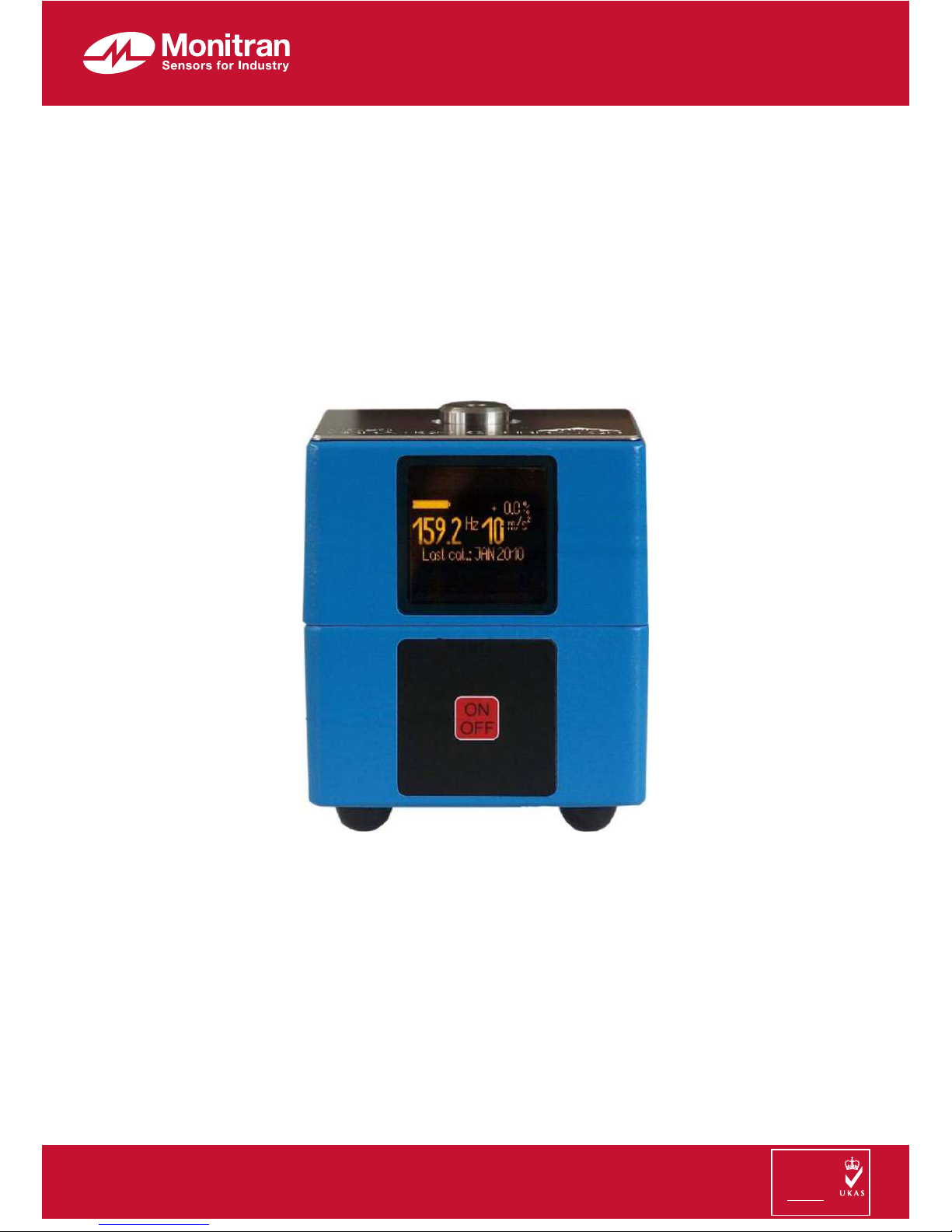
The battery indicator is located in the upper left hand corner of the display. A full
bargraph is displayed when the battery is fully charged. Even if the bargraph is
empty the instrument can still be used within its specifications for a certain period of
time. When the battery voltage drops under a critical value, the VC20 is switched
off automatically.
The instrument is equipped with a NiMH accumulator providing power for approx-
imately 5 hours of operation.
To charge the battery, connect the supplied mains plug adapter (15 VDC) to the DIN
socket at the side of the case. The unit should preferably be switched off during
charging. Charging will take about 3 hours. During the charging process the battery
indicator will be continuously moving (Figure 3).
During the charging process the VC20 can be used for calibration. However, this
will extend the necessary charging time.
The accumulator should be charged at room temperature. At higher temperatures
charging can be stopped before reaching the full capacity because of the built-in
temperature sensor.
The battery has no memory effect. Partial charging is permissible.
Permanent connection of the mains adapter is not recommended. This may lead to
premature wear of the battery. In order to avoid overcharging the battery, it is not re-
commended that you disconnect and connect the mains adapter again immediately
after charging is finished.
When the unit is not in use, the battery should be charged at least once a year.
The built-in battery is maintenance-free. Like all accumulators it has a limited num-
ber of charging cycles. If the operating time with a fully charged battery becomes in-
sufficient, the battery should be replaced. In this case, the calibrator should then be
returned to the manufacturer. In addition to replacing the battery, the manufacturer
will also test the accuracy of the calibrator.
3.4. Reset
In the unlikely event that your VC20 cannot be switched on by the “On/Off” key, it
may be necessary to press the Reset button. This button is found on the bottom side
of the case near the key pad. Use a thin non-metallic object, such as a toothpick, to
press the button inside the hole. This will start the instrument. Pressing the Reset
button has no effect on accuracy.
4
Figure 3: Charge indication

The vibration characteristics of the VC20 are very stable even after intensive use.
Typical changes are below 1 % per year. We recommend annual re-calibration. In
case of shock load, dropping the instrument, etc. immediate recalibration is advised.
Vibration magnitude (RMS values):
Vibration acceleration: 10 m/s² ± 3% at 0 to 40 °C
Vibration velocity: 10 mm/s ± 3% at 0 to 40 °C
Vibration displacement: 10 µm ± 3% at 0 to 40 °C
Vibration frequency: 159.15 Hz ±0.05% at -10 to 55 °C
Radian frequency: 1000 /s ±0.05% at -10 to 55 °C
Level indication: Percent display,
above ± 3 % beep tone
Settling time: < 10 s
Maximum weight of test object
for stated accuracy:
600 g
Vibration exciter:
Dynamic force: 10 N
Max. torque: 2 Nm
Nominal torque: 1 Nm
Max. transverse force: 20 Nm
Transverse vibration: < 10 % of main axis, measured 14 mm above
shaker
Mounting of test object: M5 tapped hole, 7 mm deep
clamping magnet
adhesive
Operating temperature ranges for:
3% accuracy
5% accuracy
0 to 40 °C
-10 to 55 °C
Humidity: < 90 % at 30 °C, no condensation
5
4: Calibration
5: Specifications

Magnetic scatter field at shaker: < 0.2 mT
Power supply: built-in NiMH accumulator, 7.2 V / 1.6 Ah
Battery operating time: approx. 5 h with m = 100 g
Automatic shut-off time: 10 min
Charge time of accumulator: 3 h
Charge socket: DIN 45323 (5.5 / 2.1)
positive terminal at center pin
Charge voltage: 11 to 18 V DC
Charge current < 1 A
Dimensions
(length x width x height): 100 x 100 x 120 mm³
Weight: 2.2 kg
© Monitran Limited 2014 HB054.1 02/2015
All products are guaranteed against defects in materials and workmanship for a
period of 24 months from the date of purchase. In the event of failure within 24
months of the original purchase the Company will promptly repair or replace any
defective products without charge.
This warranty is void if repair has been attempted by unauthorised persons or
agents, if the products have been used for purposes for which they were not
intended, if they have been subjected to abuse or wilful neglect or if the user has
in any way failed to take sufficient precautions to safeguard the products.
No liability will be accepted for loss of items or component parts.
Warranty
Table of contents