2
© 2015 Monte Carlo Fan Company 1/25/2015
Warning: Before proceeding, be sure to shut off electricity
at main switch or circuit breaker in order to avoid electrical
shock.
Note: Before installing the wall transmitter, place it in OFF
position. (Fig.2)
Make series-wound connection for the wall controller with
HOT wire from house and lead wires from fan.
Connect the black/white wire marked “AC IN L” from wall
controller to the HOT wire from house and then connect the
black wire marked “TO MOTOR L” of wall controller to the
fan lead wire from fan in outlet box. Connect the blue wire
marked “FOR LIGHT” from wall controller to the light lead
wire from fan (fan with light)
Connect green/yellow grounded wire to grounded wire from
outlet box.
Install the wall controller to outlet box using machine screws
provided.
Attach wall plate to wall control unit with screws provided.
Wall Control Installation and Wiring
Wall plate
Black/White(AC IN L)
Blue (FOR LIGHT)
Black (TO MOTOR L)
120V/60HZ
Power supply
WHITE (Neutral)
BLUE
BLACK
Wall controller
Outlet box
Green/Yellow (Grounding)
BLACK (Live)
Operation
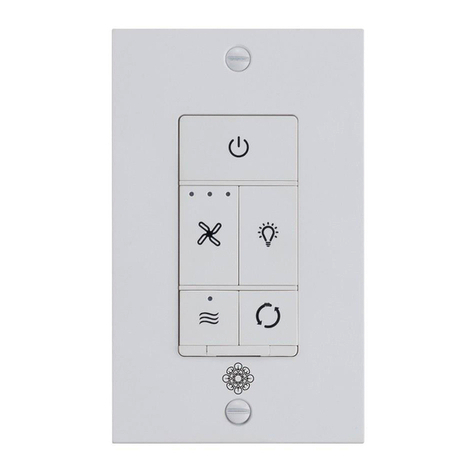
This wall controller provides 4 fan
speeds, light on/off and light
dimming control.(Fig.2)
1 - High - , 2 - Medium high , 3 -
Medium , 4 - Low , - Off.
Light on/off and dimming.
Fig.1
Off
ON and Dimming
Fig.2


