Montesa COTA 4RT 260 2023 User manual

PGM-FI Racing Trial
2023
Owner’s Manual

Important
This motorcycle is designed and constructed as an operator-only model. The motorcycle load limit and seating configuration do not safety permit the carrying
of a passenger.
Read this manual carefully.
This manual should be considered as a permanent part of the motorcycle and should remain with the motorcycle when resold.
Safety Messages
Your safety and the safety of others is very important. We have provided
important safety messages in this manual and on the COTA 4RT. Please read
these messages carefully.
A safety message alerts you to potential hazards that could hurt you or others.
Each safety message is preceded by a safety alert symbol and one of three
words, DANGER, WARNING, or CAUTION.
These signal words mean:
!DANGER You WILL be KILLED or SERIOUSLY HURT if you
don’t follow instructions.
!WARNING You CAN be KILLED or SERIOUSLY HURT if you
don’t follow instructions.
!CAUTION You CAN be HURT if you don’t follow instructions.
Each message tells you what the hazard is, what can happen and what you can
do to avoid or reduce injury.
Damage Prevention Messages
You will also see other important messages that are preceded by the word
NOTICE.
This word means:
NOTICE
Your COTA 4RT or other property can be damaged if you don’t follow
instructions.
The purpose of these messages is to help prevent damage to your COTA
4RT, other property, or the environment.
2023
V03

MONTESA COTA 4RT
Owner’s Manual
The following diagram shows the 2 different versions of the COTA 4RT model:
ED Street version, COTA 4RT-260 3ED Racing version, COTA 4RT-260
All information in this publication is based on the latest product information available at the time of approval for printing.
MONTESA HONDA, S.A.U. reserves the right to make changes at any time without notice and without incurring any obligation.
No part of this publication may be reproduced without written permission.

(1) FRAME NUMBER (1) ENGINE NUMBER
Serial numbers
The Vehicle Identification Number (VIN) is stamped on the
right side of the steering head.
The serial number of the engine is stamped on the lower
right side of the crankcase. MODEL TYPE FRAME No. ENGINE No.
MRT 260 P ED *VTDNE13B?PE000001* NN4E5209001
MRT 260 P 3ED *VTDNE04C?PE000001* NN4E5209001
11

Labels
The following pages show the meanings and locations of the labels on your Cota.
Others provide important safety information. Read this information carefully and don’t remove the labels.
If a label comes off or becomes hard to read, contact your dealer for a replacement.
There is a specific symbol on each label. The meanings of each symbol and label are as follows.
1
Tire information (ED)
Cold tire pressure (driver only)
Front: 100kpa
Rear: 100kpa
Keep chain adjusted and lubricated (ED)
25-35 Mm (1.0 -1.4 In)
Read owners manual
Keep chain adjusted and lubricated (3ED)
25-35 Mm (1.0 -1.4 In)
Read owners manual
2
95
+
Caution label
- This motorcycle is not designed to transport a passenger.
- Read owner’s manual carefully.
- For yourprotection always wear your helmet while riding.
- Ethanol (ethyl alcohol) 5% by volume.
- Ethanol (ethyl alcohol) 7% by volume.
- Use unleaded gasoline, octane number 95 (RON) or higher.
3
Radiator cap label
Danger
-Never open when hot.
-Hot coolant will scald you.
-Relief pressure valve begins to open at 1.1 Kgf/cm
2
.
4
Safety label (3ED)
(*) Depending on the final destination of the motorcycle
5
UK/CA CE label (3ED)
6EU Authorised Representative:
Honda Motor Europe Ltd.
- Aalst Office
Wijngaardveld 1 (Noord V)
9300 Aalst- Belgium
MADE IN SPAIN
Authorised Representative label (ED)
7UK Importer:
Honda Motor Europe Ltd.
Cain Road
Bracknell, RG12 1HL
United Kingdom
UK Importer label (3ED)

Labels (ED)
3
2
1
6

Labels (3ED)
4
3
2
1
7
5

Important Safety Precautions
Your Cota can provide many years of pleasure, if you
take responsibility for your own safety and understand
the challenges you can meet in competitive racing.
As an experienced rider, you know there is much you can
do to protect yourself when you ride.
The following are a few precautions we consider to be
most important.
Never Carry a Passenger.
Your Cota is designed for one operator only.
Carrying a passenger can cause crashes in which you and
others can be hurt.
Wear Protective Gear.
Whether you’re practicing to improve your skills, or riding
in competition, always wear an approved helmet, eye
protection, and proper protective gear.
Take Time to Get to Know Your Cota.
Because every motorcycle is unique, take time to become
thoroughly familiar with how this one operates and
responds to your commands before placing your machine,
and yourself, in competition.
Learn and Respect Your Limits.
Never ride beyond your personal abilites or faster than
conditions warrant. Remember that alcohol, drugs, illness
and fatigue can reduce your ability to perform well and
ride safely.
Don’t Drink and Ride.
Alcohol and riding don’t mix. Even one drink can reduce
your ability to respond to changing conditions, and your
reaction time gets worse with every additional drink. So
don’t drink and ride, and don’t let your friends drink and
ride either.
Keep your Montesa in Safe Condition.
Maintaining your Cota properly is critical to your safety. A
loose bolt, for example, can cause a breakdown in which
you can be seriously injured.
Accessories & Modifications
Modifying your Cota or using non-Montesa accessories
can make your Cota unsafe.
Before you consider making any modifications or adding
an accessory, be sure to read the following information.
!WARNING
Improper accessories or modifications can cause a
crash in which you can be seriously hurt or killed.
Follow all instructions in this owner’s manual regarding
modifications and accessories.
Accessories
We strongly recommend that you use only Montesa
Genuine accessories that have been specifically designed
and tested for your Cota. Because Montesa cannot test
all other accessories, you must be personally responsible
for proper selection, installation, and use of non-Montesa
accessories.
Check with your dealer for assistance and always follow
this guideline:
yMake sure the accessory does not reduce ground clea-
rance and lean angle, limit suspension travel or steering
travel, alter your riding position, or interfere with ope-
rating any controls.
Modifications
We strongly advise you not to remove any original
equipment or modify your Cota in any way that would
change its design or operation.
Such changes could seriously impair your Cota’s handling,
stability, and braking, making it unsafe to ride.
General Competition Maintenance
Perform maintenance on firm, level ground using the side
stand, a workstand, or equivalent support.
When tightening bolts, nuts or screws, start with the
larger diameter or inner fasteners, and tighten them to
the specified torque using a crisscross pattern.
Use Montesa Genuine Parts or their equivalent when
servicing your Cota.
Clean parts in non-flammable (high flash point) cleaning
solvent (such as kerosene) when disassembling. Lubricate
any sliding surface, Orings, and seals before reassembling.
Grease parts by coating or filling where specified.
After any engine disassembly, always install new gaskets,
O-rings, cotter pins, piston pin clips, snap rings, etc. when
reassembling. After reassembly, check all parts for proper
installation and operation.

Contents
1. Operating instructions
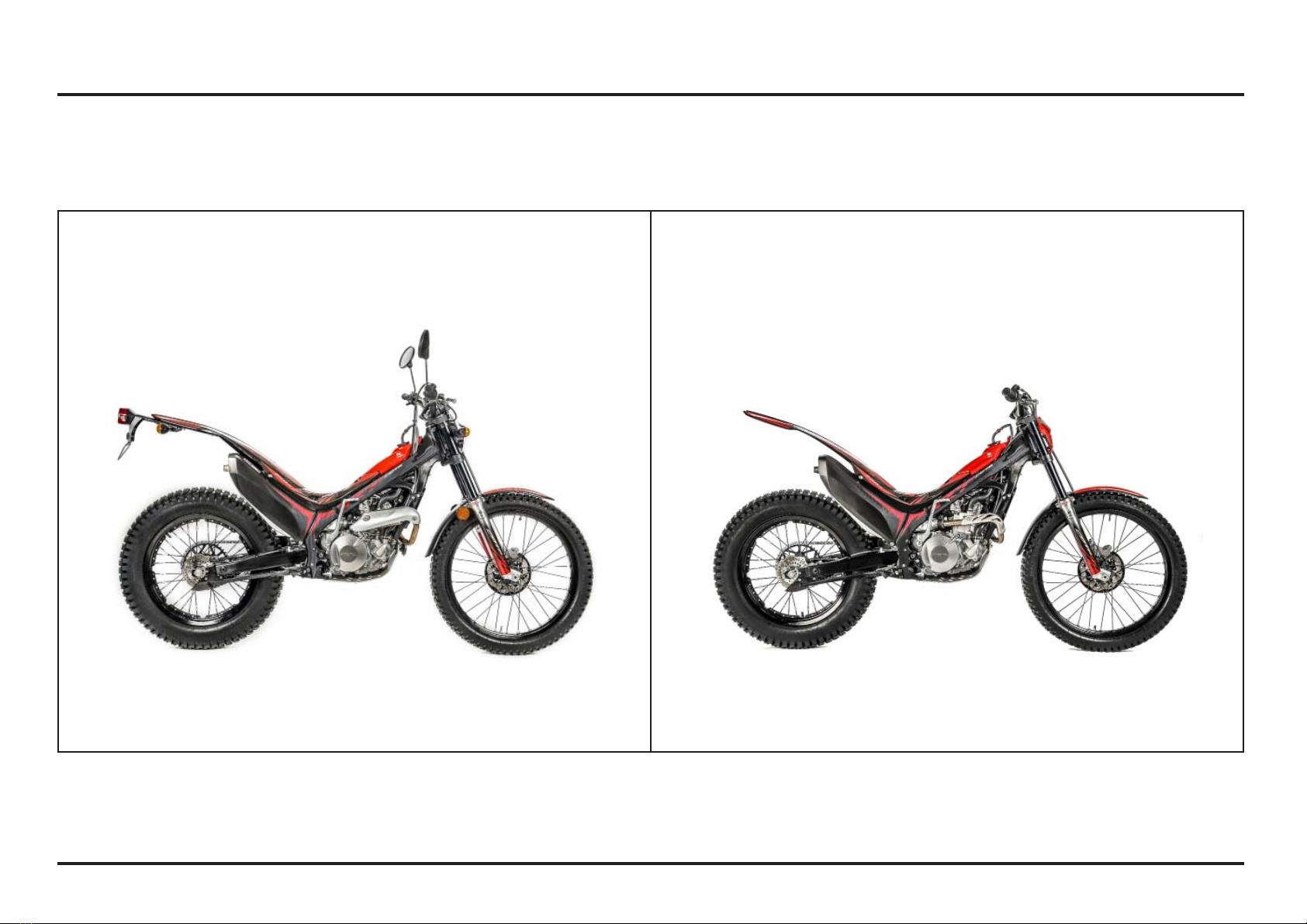
Operation component locations (ED) ............... 1-1
Operation component locations (3ED).............. 1-2
Fuel ............................................................ 1-3
Coolant ....................................................... 1-3
Basic Operation ............................................ 1-3
Odometer/Speedometer (ED) .......................... 1-5
Steering lock (ED)......................................... 1-7
Shifting gears .............................................. 1-7
Braking ....................................................... 1-8
Parking........................................................ 1-8
Controls ...................................................... 1-8
2. Service data
Specifications .............................................. 2-1
Service data................................................. 2-2
Torque Values.............................................. 2-5
Tools .......................................................... 2-7
Special........................................................ 2-7
Lubrication & Seal Points............................... 2-8
Cable & Harness Routing ............................... 2-11
3. Service and maintenance
Maintenance schedule................................... 3-1
Pre-ride Inspection ........................................ 3-1
Warming-up Inspection.................................. 3-2
Ride Inspection............................................. 3-2
After Ride Inspection .................................... 3-2
Replacement Parts ........................................ 3-2
Fuel Line ..................................................... 3-3
Air Cleaner .................................................. 3-3
Spark Plug ................................................... 3-4
Valve Clearance ........................................... 3-4
Engine Oil/Oil Filter ....................................... 3-6
Engine Idle Speed ......................................... 3-8
Transmission Oil........................................... 3-8
Coolant ....................................................... 3-9
Clutch System ............................................. 3-10
Exhaust Pipe And Muffler .............................. 3-10
Drive Chain.................................................. 3-11
Drive Chain Slider ......................................... 3-11
Drive/Driven Sprockets.................................. 3-12
Brake Fluid .................................................. 3-13
Brake Pad Wear............................................ 3-14
Brake System............................................... 3-14
Handlebar And Steering Head Bearings............ 3-15
Wheels And Tires ......................................... 3-15
Front Suspension..........................................
3-16
Fork............................................................ 3-16
Rear Suspension........................................... 3-17
Front headlight and front and rear position light.3-18
Cleaning...................................................... 3-19
Storage ....................................................... 3-19
4. Engine servicing
Oil Pressure Relief Valve................................ 4-1
Oil Pump ..................................................... 4-1
Disassembly / Installation of fuel feed hose .... 4-4
Fuel Line Inspection ...................................... 4-5
Fuel Tank/Fuel Pump..................................... 4-7
Injector ....................................................... 4-13
Throttle Body ............................................... 4-13
Water Seal And Bearing Replacement.............. 4-15
Radiator Removal/Installation ......................... 4-17
Engine Removal/Installation............................ 4-18
Cylinder Compression ................................... 4-20
Cylinder Head Cover/Camshaft Removal .......... 4-20
Cylinder Head Removal ................................. 4-23
Cylinder Head Disassembly ............................ 4-25
Cylinder Head Inspection ............................... 4-26
Valve Guide Replacement .............................. 4-27
Valve Seat Inspection/Refacing ...................... 4-28
Cylinder Head Assembly................................ 4-31
Cylinder/Piston ............................................. 4-32
Cylinder Head Installation .............................. 4-37
Camshaft/Cylinder Head Cover Installation....... 4-38
Right Crankcase Cover .................................. 4-40
Clutch Slave Cylinder .................................... 4-41
Clutch......................................................... 4-43
Kickstarter................................................... 4-46
Gearshift Linkage.......................................... 4-47
Left Crankcase Cover.................................... 4-49
Flywheel ..................................................... 4-52
Crankcase Separation/Disassembly ................. 4-54
Crankshaft/Transmission Inspection ................ 4-56
Crankcase Bearing Replacement ..................... 4-56
Transmission Assembly ................................. 4-58
Crankcase Combination ................................. 4-59
5. Frame servicing
Front Wheel ................................................. 5-1
Fork............................................................ 5-3
Steering stem .............................................. 5-12
Rear Wheel .................................................. 5-14
Shock Absorber............................................ 5-16
Shock Linkage
.............................................. 5-19
Swingarm.................................................... 5-20
Brake pad replacement .................................. 5-23
Front brake caliper ........................................ 5-25
Rear brake caliper ......................................... 5-26
Front master cylinder .................................... 5-27
Rear master cylinder ..................................... 5-28
Brake pedal.................................................. 5-28
Clutch master cylinder .................................. 5-29
6. Electrical servicing
Charging system inspection ........................... 6-1
Ignition system inspection ............................. 6-3
PGM-FI System inspection ............................. 6-5
MIL and DTC (ISO) error codes for
the PGM-FI injection system. ......................... 6-9
Bank angle sensor inspection ......................... 6-10
Engine stop switch inspection ........................ 6-11
Cooling fan system inspection........................ 6-11
Chapter lights / instruments / switches (ED)..... 6-12
Indicator light/Indicator light relay ................... 6-13
Speed sensor ............................................... 6-16
Wiring diagram (ED) ...................................... 6-18
Wiring diagram (3ED) .................................... 6-19
7. Manufacturer and authorized representative for
the European and UK markets
Manufacturer ............................................... 7-1
Authorized Representative: European market (ED) 7-1
Authorized Representative: United Kingdom ....... 7-1
CE Declaration of conformity ......................... 7-3
UK CA Declaration of conformity.................... 7-5

How To Use This Manual
The purpose of this Owner’s Manual is to help ensure that
you obtain the greatest possible satisfaction from your
new COTA trialer; satisfaction with the performance of
the motorcycle, and through success in competition.
If you plan to do any service on your COTA, section 3
describes standard maintenance and sections 4 through
6 contain in information on repair, disassembly, assembly
and special tools.
Follow the Maintenance Schedule recommendation
(page 3-1) to ensure that your COTA is always in peak
operating condition.
Importance Of Proper Preparation
Proper pre-competition preparation and regular service
is essential to rider safety and the reliability of the
motorcycle. Any error or oversight made by the technician
during preparation or servicing can easily result in faulty
operation, damage to the machine, or injury to the rider.
Parts Availability
Orders for the parts tend to be concentrated during the
season, so you need to plan your parts orders carefully.
To prevent delays in shipment, place orders on regularly
replaced and fast-wearing parts well ahead of the season
(page 3-2).
To The New Owner
By selecting a MONTESA COTA 4RT as your new
machine, you have placed yourself in a distinguished
family of owners and riders.
The COTA is a high performance trial motorcycle utilizing
the latest trial technology. This motorcycle is intended for
competition use by experienced riders only.
This new trialer was designed to be as competitive as
possible. But motorcycle trial is a physically demanding
sport that requires more than just a fine racing machine.
To do well, you must be in excellent physical condition
and be a skillful rider. For the best possible results, work
diligently on your physical conditioning and practice
frequently.
The purpose of this Manual is to help ensure that you
obtain the greatest possible satisfaction from your new
COTA trialer.
Start-up recommendations
Adjusting the idle
If using your motorcycle at different heights, bear in mind
that you must adjust the idle; otherwise, you may have
problems operating the vehicle. (See page 3-8)
Engine start
If you have problems starting your vehicle, follow the
steps below:
1. Open the throttle all the way (100%) and hold.
2. Without releasing the throttle, operate the kick-starter
once or twice.
3. Close the throttle and start your motorcycle as normal
(page 1-3).

Memo

1-1
1-1
1. Operating instructions
Operation component locations (ED)
kickstarter
rear brake pedal
clutch lever
front brake lever
throttle grip
engine stop button
rearview mirror rearview mirror
shift lever
light control, turn signal & horn switch

Operating instructions
1-2
1-2
Operation component locations (3ED)
throttle grip
front brake leverclutch lever
shift lever
kickstarter
rear brake pedal
mapping switch
engine stop button

Operating instructions
1-3
1-3
(1) BREATHER HOSE
(2) FUEL TANK CAP
(1) RADIATOR CAP (1) KICKSTARTER PEDAL
Fuel
Gasoline: Unleaded gasoline, pump octane number 95
(RON) or higher.
Fuel tank capacity:
2.0 ± 0.2 liter (0.52 US gal, 0.43 Imp gal)
Disconnect the breather hose from the fuel filler cap.
Turn the fuel tank cap counterclockwise, then remove the
cap.
!WARNING
Gasoline is highly flammable and is explosive.
You can be burned or seriously injured when refueling.
yStop engine and keep heat, sparks, and flame away.
yRefuel only outdoors.
yWipe up spills immediately.
Install the fuel tank cap by turning it clockwise.
Connect the breather hose to the fuel filler cap.
Coolant
The engine of COTA is a water-cooled type. In order to
provide adequate cooling, it is essential that the radiator
be filled with coolant up the proper level (See pag. 3-9).
Coolant: 50/50 Mixture of Coolant and Distilled Water
!WARNING
Removing the radiator cap while the engine is hot will
allow the coolant to spray out, seriously scalding you.
Always let the engine and radiator cool down before
removing the radiator cap.
NOTICE
When filling the coolant system, be sure to bleed air
completely. If not, the system cannot be sufficiently filled
and will cause overheating.
Basic Operation
Starting The Engine
Your COTA exhaust contains poisonous carbon monoxide
gas. High levels of carbon monoxide can collect rapidly in
enclosed areas such as a garage. Do not run the engine
with the garage door closed. Even with the door open,
run the engine only long enough to move your COTA out
of the garage.
Cold Engine Starting
1. Shift the transmission into neutral.
2. Release the side stand all the way.
3. With the throttle fully closed, operate the kickstarter.
Starting from the top of the kickstarter stroke, kick
through to the bottom with a rapid, continuous motion.
4. After the engine starts, run it for a few minutes, “blip-
ping” the throttle, until it warms up enough to idle.
!WARNING - VERY IMPORTANT
1
2
1
1

Operating instructions
1-4
1-4
Break-In Procedure
New Motorcycle
Following proper break-in procedure helps ensure that
the most important and expensive components on your
new motorcycle will provide maximum performance and
service life. (Also follow proper break-in procedure for a
newly rebuilt engine.)
When riding a new motorcycle, operate the motorcycle
for the first 20 minutes using not more than half throttle
and shifting gears so that the engine does not lug:
Reconditioned Motorcycle
yAfter replacing the cylinder and crankshaft, operate the
motorcycle 20 minutes observing the same cautions as
for a new motorcycle.
yWhen the piston, piston ring, gears, etc. are replaced,
they must be broken in observing the first 30 minutes
using not more than half throttle and shifting gears so
that the engine does not lug
When you shift the transmission into gear, apply front
brake to prevent the motorcycle move forward.
Stopping The Engine
1. Shift the transmission into neutral.
2. Push the engine stop button until the engine stops
completely.
(1) ENGINE STOP BUTTON
(1) SIDE STAND
(2) SIDE STAND SPRINGS
Side Stand
The side stand is used to support your Cota while parked.
To operate, use your foot to lower the side stand until it
is fully extended.
Before riding, raise the side stand.
Inspection
1. Check the stand springs for damage or loss of tension.
2. Check the side stand assembly for freedom of
movement.
If the stand is stiff or squeaks, clean the area around
the pivot and lubricate the pivot bolt with grease or oil
lubricant.
NOTICE
Do not start the motorcycle while supported on the side
stand, which could be bent.
2
1
3ED
3ED
ED
ED 1
1

Operating instructions
1-5
1-5
(1) SPEEDOMETER
(2) ODOMETER
(3) CLOCK
(4) RIDE TIME
(5) TURN SIGNAL INDICATOR
(6) HIGH BEAM INDICATOR
(7) MALFUNCTION INDICATOR LAMP (MIL)
Odometer/Speedometer (ED)
Instruments
ySpeedometer: Shows riding speed. This shows your
speed in kilometres per hour (km/h) or miles per hour
(mph).
yOdometer: shows accumulated mileage in “TOTAL”,
“TRIP A” and “TRIP B” modes.
yClock: Shows hour and minute.
yRide time: shows the ride time in “TOTAL”, “TRIP A”
and “TRIP B” modes.
Indicators
The indicators are located in the speedometer.
yHigh beam indicator (blue): Lights when the headlight
is on high beam
yTurn signal indicator (green): Flashes when the turn
signal operates.
yMalfunction indicator lamp (MIL). When any abnorma-
lity occurs in the system, the ECM turns on the MIL.
Setting mode
The main screen is used to adjust the following settings:
1. Changing the speed units:
1. Start the motorcycle.
2. Press the (SET) button.
– Press less than 2 seconds to display the ride time
(hour) or mileage (km / mi).
– Press and hold more than 10 seconds, the speed
units will change from km/h to mph and vice versa,
depending on their initial setting.
(1) (MODE) BUTTON
(2) (SET) BUTTON
2. Changing from “TOTAL”, “Trip A” o “Trip B”.
1. Start the motorcycle.
The “TOTAL” distance is displayed by default.
2. Press the (MODE) button.
– Press less than 2 seconds to display “TOTAL”,
“TRIP A” o “TRIP B”.
3. Press the (SET) button.
– Press less than 2 seconds to display the ride time
(hour) or accumulated mileage (km / mi).
To reset “TRIP A” or “TRIP B”, select the desired condi-
tion (accumulated mileage or ride time). Press and hold
the (SET) button for more than 2 seconds.
ED
ED
ED
ED
ED
ED
ED
ED
13
2
56
7
12
4

Operating instructions
1-6
1-6
3. Clock settings
The clock will be displayed in 24h format if the unit of
measure is set to km.
The clock will be displayed in 12h format if the unit of
measure is set to mi.
1. Start the motorcycle.
2. Press the (MODE) + (SET) buttons.
– Press and hold more than 2 seconds. The clock will
be set in the adjust mode with the hour display flas-
hing.
– Press the (MODE) button to change the hours.
yPress less than 2 seconds, the digit will increase
by one hour each time the button is pressed.
yKeep the button pressed, the hour digit advances
fast, release the button when the desired time is
displayed.
- Press the (SET) button to change the minutes.
yPress less than 2 seconds, the digit will increase
by one minute each time the button is pressed.
yKeep the button pressed, the minute digit advan-
ces fast. Release the button when the desired
minute is displayed.
3. Press the (MODE) + (SET) buttons.
– Press and hold more than 10 seconds to save the
new values and exit the clock setting mode.
– If no button is pressed for more than 10 seconds,
the clock setting mode will end without saving the
changes.
4. Coin battery
Odometer/Speedometer is equipped with a coin battery
for keeping time when motorcycle is off.
Coin size: CR2032
(1) COIN BATTERY
24h 12h
ED
ED
ED
ED
ED
ED
1

Operating instructions
1-7
1-7
(1) STEERING LOCK
Steering lock (ED)
The steering lock is on the steering stem. To lock the
steering, turn the handlebar all
the way to the left, insert the steering key into the lock,
turn the key counterclockwise
as far as possible. Then, press the lock all the way in, turn
the key back to the original
position, and remove the key.
To unlock the steering, perform the locking sequence in
the reverse order.
Shifting gears
Your Cota has five forward gears in a one-down, four-up
shift pattern.
To start riding, after the engine has been warmed and the
side stand raised.
1. Close the throttle and pull the front brake lever in.
2. Pull the clutch lever all the way in.
3. Depress the shift lever from neutral down to first gear.
4. Release the front brake lever. Gradually open the
throttle while you slowly release the clutch lever. If the
engine min-1 (rpm) (speed) is too low when you release
the clutch lever, the engine will stall.
If the engine min-1 (rpm) (speed) is too high or you
release the clutch lever too quickly, your Cota may
lurch forward.
5. When you attain a moderate speed, close the throttle,
pull the clutch lever in, and raise the shift lever. After
shifting, release the clutch lever and apply the throttle.
6. To continue shifting up to each higher gear, repeat step 5.
7. To shift down to a lower gear, close the throttle, pull
the clutch lever in, and depress the shift lever. After
shifting, release the clutch lever and apply the throttle.
Remember to close the throttle and pull the clutch lever in
completely before shifting.
NOTICE
Improper shifting may damage the engine, transmission,
and drive train.
Learning when to shift gears comes with experience.
Upshift to a higher gear or reduce throttle before engine
min-1 (rpm) (speed) gets too high. Downshift to a lower
gear before you feel the engine laboring (lugging) at low
min-1 (rpm).
NOTICE
Downshifting can help slow your motorcycle, especially
on downhills. However, downshifting when engine min-1
(rpm) is too high can cause engine damage.
NOTICE
To prevent transmission damage, do not coast or tow the
motorcycle for long distances with the engine off.
1
ED
ED

Operating instructions
1-8
1-8
Clutch Lever
The clutch lever free play can be adjusted by turning the
adjuster.
Free play must be adjusted to provide 0.5 – 1.5 mm
(0.019 – 0.060 in) clearance between the end of the
adjuster and the clutch master cylinder piston.
yTo reduce free play, turn the adjuster clockwise, then
tighten the lock nut securely.
yTo increase free play, turn the adjuster counterclockwi-
se, then tighten the lock nut securely.
If the clutch will not disengage or motorcycle creeps
with clutch disengaged,there is probably air in the clutch
system and it must be bled.
NOTICE
Do not adjust the end of the adjuster and the clutch mas-
ter cylinder piston below 0.5 mm (0.019 in).
(1) ADJUSTER
(2) LOCK NUT
Braking
To slow or stop, apply the front brake lever and rear brake
pedal smoothly, while downshifting to match your speed.
Gradually increase braking as you feel the brakes slowing
your speed. To prevent stalling the engine, pull the clutch
lever in before coming to a complete stop. For support,
put your left foot down first, then your right foot when
you are through using the rear brake pedal.
For maximum braking, close the throttle and firmly apply
the front brake lever and rear brake pedal controls.
Applying the brakes too hard may cause the wheels to
lock and slide, reducing control of your Cota. If this hap-
pens, release the brake controls, steer straight ahead until
you regain control, then reapply the brakes more gently.
Generally, reduce your speed or complete braking befo-
re beginning a turn. Avoid braking or closing the throttle
quickly while turning. Either action may cause one or both
wheels to slip. Any wheel slip will reduce your control of
your Cota.
When riding in wet or raining conditions, or on loose sur-
faces, the ability to maneuver and stop will be reduced.
All of your actions should be smooth under these condi-
tions. Rapid acceleration, braking, or turning may cause
loss of control. For your safety, exercise extreme caution
when braking, accelerating, or turning.
When descending a long, steep grade, use engine com-
pression braking by downshifting, with intermittent use
of both brakes.
When you brake to a stop, pull the clutch lever in before
stopping completely to prevent stalling the engine. For
support, put your left foot on the ground first, then your
right foot when you have finish braking.
Parking
Lower the side stand to support your Cota.
Always choose a level surface to park.
Controls
Clutch
Your COTA has a hydraulically actuated clutch. There are
no adjustments to perform but the clutch system must be
inspected periodically for fluid level and leakage.
If the control lever free play becomes excessive and the
motorcycle creeps or stalls when shifted into gear, or if
the clutch slips, causing acceleration to lag behind engine
speed, there is probably air in the clutch hydraulic system
and it must be bled out.
(1) UPPER LEVEL LINE
1
2
1
ED
ED
3ED
3ED
1

Operating instructions
1-9
1-9
Throttle Grip
Throttle Grip Free Play
Standard throttle grip free play is approximately 3 mm
(0.12 in) of grip rotation.
Adjustment is made with the integral throttle cable
adjuster.
Slide the dust cover off from the integral cable adjuster.
Turning the adjuster in direction “A” will decrease free
play and turning it in direction “B” will increase free play.
Tighten the lock nut after adjustment.
Operate the throttle grip to ensure that it functions
smoothly and returns completely in all steering position.
(1) DUST COVER (A) DECREASE
(2) LOCK NUT (B) INCREASE
(3) ADJUSTER
(1) HEADLIGHT DIMMER SWITCH
Headlight dimmer switch
Turn the dimmer switch to to select high beam or to
to select low beam.
(1) CLUTCH LEVER
(2) FREE PLAY
Clutch Lever Free Play
Standard cluth lever free play should be between
0.5 – 15 mm (0.019 – 0.60 in).
NOTICE
Do not adjust the free play of the lever to less than 5 mm
(0.196 in).
2
1
ED
ED
1
A
B
A
1
2
3
Other manuals for COTA 4RT 260 2023
1
Table of contents
Other Montesa Motorcycle manuals

Montesa
Montesa 4Ride MST260 2016 Install guide

Montesa
Montesa COTA 301RR 2023 User manual

Montesa
Montesa 4Ride 2017 Manual

Montesa
Montesa COTA 300RR 2018 User manual

Montesa
Montesa COTA 4RT 260 2023 User manual

Montesa
Montesa COTA 4RT 2005 User manual

Montesa
Montesa COTA 4RT RACE REPLICA User manual

Montesa
Montesa Cota 300 RR 2017 Manual

Montesa
Montesa COTA 4RT 260R 2022 User manual

Montesa
Montesa COTA 4RT 250 2023 User manual