Page 2
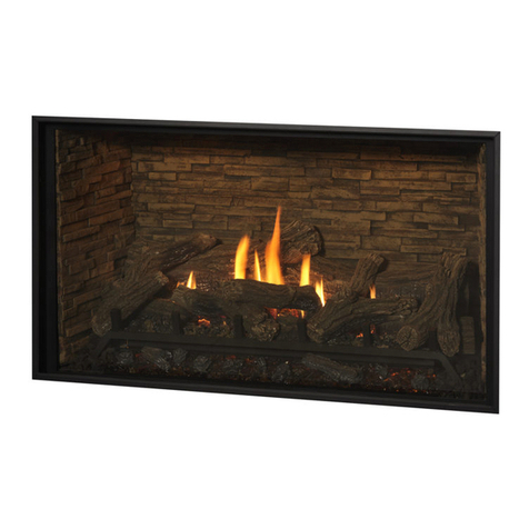
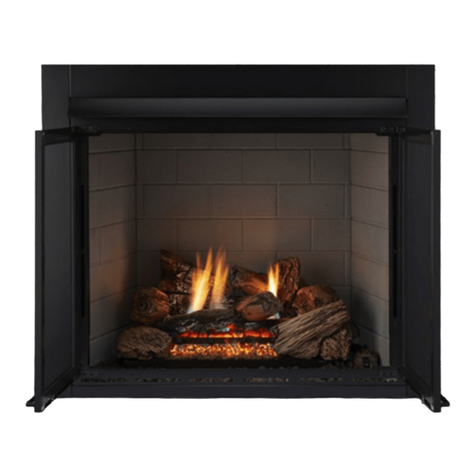
H*38DF-PFC* Indoor Gas Fireplace
Part No. XG0816 - 100210
▪ Section 3-3-2: Venting Components ............................. 14
▪ Section 3-3-3: Heat Shields ......................................... 15
▪ Installing a RHS8 Wall Mounted Heat Shield ......... 15
▪ Installing a RHS101 Wall Mounted Heat Shield ...... 15
Section 4: Wiring ................................................................... 16
▪ Honeywell gas control and pilot .......................... 16
▪ SIT - IPI gas control and pilot ............................... 16
Section 5: Installing the Gas Line .......................................... 17
Section 5-1: Fuel Conversion ........................................ 17
Section 5-2: Gas Pressure ............................................ 17
Section 5-3: Gas Connection......................................... 17
Section 6: Finishing ............................................................... 18
▪ Finishing around the replace .................................. 18
▪ Installing the nailing ange extension ........................ 18
Section 7: Installing and Removing the Door ........................ 19
Section 8: Installing the Accessories ..................................... 20
▪ Installing the H38PF* Log set ................................... 20
▪ Installing the HL38PF* Firestones ............................ 21
Section 9: Operation .......................................................22 - 24
▪ Start-up Sequence with Continuous Pilot .................. 22
▪ Start-up Sequence with Honeywell Electronic Ignition 23
▪ Start-up Sequence SIT-IPI Gas valve ....................... 24
Maintenance ...................................................................25 - 26
▪ General ................................................................. 25
▪ Cleaning ................................................................ 25
▪ SIT Hi-Lo Burner Adjustment ................................... 25
▪ SIT Pilot Burner Adjustment .................................... 25
▪ Troubleshooting ...................................................... 26
SIT- Nova 820 Gas Control Valve ....................... 26
SIT- IPI Electronic Gas Control Valve ................. 26
▪ Parts List ............................................................... 27
Appendix
A. Termination Locations .......................................... 28
B. Warranty ............................................................ 29
C. State of Massachusetts. ...................................... 30
Safety Alert Key
Introduction ............................................................................... 3
Models............................................................................ 3
Installation
Before you Start ............................................................. 4
Installation Checklist ...................................................... 4
Section 1: Installation Overview and Product Dimensions ...... 5
Section 2: Framing the Fireplace ............................................. 6
Clearances ........................................................ 6
Installing the Standoffs ...................................... 7
The Nailing Flange Extension ........................... 7
Section 3: The Direct Vent System ...................................8 - 10
Section 3-1: Converting from Top Vent to Rear Vent .... 8
Section 3-2: Installing a Roof mounted Termination 9 - 10
▪ Section 3-2-1: Venting Layout ...................................... 9
▪ Roof mounted Terminations
Standard Top Vent (no elbows or offsets)............. 9
Top Vent (two elbows one offset) ......................... 9
Top Vent (multi-elbows and offsets) ..................... 9
Standard Roof Vent (one elbows no offsets) ..... 10
▪ Section 3-2-2: Venting Components ........................... 10
Section 3-3: Installing a Wall mounted Termination .... 11
▪ Standard PTO Installation .................................... 11
▪ Pre-installed MSR Frame .................................... 11
▪ Pre-installed BSR Frame ..................................... 11
▪ Installing MOSR Frame ....................................... 11
▪ Installing VSS Termination Shield ......................... 11
▪ Installing PTKOG Heat Guard .............................. 11
▪ Section 3-3-1: Venting Layout ............................12 - 13
▪ Top Vent, Wall mounted Graph, H*38PF* .............. 12
▪ Top Vent, Wall mounted termination (one elbow) .... 12
▪ Top Vent, Wall mounted termination (multi elbow) ... 12
▪ Rear Vent, Wall mounted Termination Graph ......... 13
▪ Standard Rear Vent, (no elbows or offsets) ........... 13
▪ Rear Vent, Wall mounted termination (two elbows) . 13
Warning:
Read this manual before installing, operating or troubleshooting this appliance.
Please retain this owner's manual for future reference.
Table of Contents
