Montigo CabanaFire PL42VO Instruction Manual

Page 1 XG0219 - 160819
Installation & Maintenance Manual
• Theinstallationofthisreplacemustbedonebyaqualiedand
certiedgasapplianceinstaller.
• Checklocalcodesandreadallinstructionspriortoinstallation.
• Installer:leavethismanualwiththeappliance.
• Consumer:retainthismanualforfuturereference.
®
C
US
WARNING:Iftheinformationintheseinstructionsisnotfollowed
exactly,areorexplosionmayresultcausingpropertydamage,
personalinjuryorlossoflife.
• For outdoor use only
•Do not store or use gasoline or other ammable vapors and
liquids in the vicinity of this or any other appliance.
• Do not touch glass until cooled.
• Do not allow children to touch glass.
•WhatToDoIfYouSmellGas:
• Do not try to light any appliance.
• Do not touch any electrical switch; do not use any phone
in your building.
• Immediately call your gas supplier from a neighbor's
phone. Follow the gas supplier's instructions.
• If you cannot reach your gas supplier, call the re
department.
• Installationandservicemustbeperformedbyaqualiedinstaller,
serviceagencyorthegassupplier.
CARBON MONOXIDE HAZARD
Thisappliancecanproducecarbon
monoxide,whichhasnoodor.
Usingitinanenclosedspacecan
killyou.
Neverusethisapplianceinan
enclosedspacesuchasacamper,
tent,carorhome.
WARNING:ForOutdoorUseOnly.
DANGER
CabanaFire PL42VO
Outdoor Gas Fireplace
28,000 btu/hr Natural Gas or LP Gas

General Information & Safety
Page 2 XG0219 - 160819
Contents
ConditionsandLimitations......................................................................................................... 3
GettingStarted............................................................................................................................. 4
Gaslineandconnection:..................................................................................................... 4
Electrical:............................................................................................................................. 4
SafeOperatingPractices............................................................................................................. 5
Certification................................................................................................................................. 6
RatingPlateLocation:......................................................................................................... 6
ExpandedRatingPlateLocation:........................................................................................ 6
ApplianceCertification................................................................................................................ 7
Certification......................................................................................................................... 7
InstallationStandards:....................................................................................................... 7
HighAltitudeInstallations:.................................................................................................. 7
OperationalWarnings.................................................................................................................. 7
Dimensions.................................................................................................................................. 8
PL42VODimensions............................................................................................................. 8
ControlBoxDimensions...................................................................................................... 8
LocationConsiderations.............................................................................................................. 9
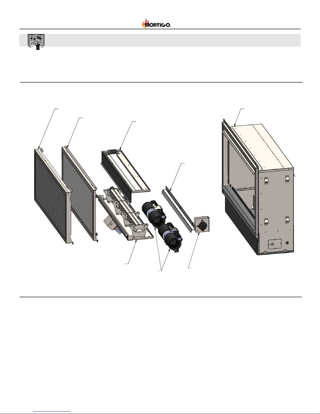
ExplodedPartView.................................................................................................................... 10
ToolsandSuppliesrequired...................................................................................................... 10
ToolList.............................................................................................................................. 10
SupplyList......................................................................................................................... 10
Gassupplyrequirements.......................................................................................................... 11
ElectricalRequirements............................................................................................................ 11
Framing...................................................................................................................................... 12
In The Wall Installation...................................................................................................... 12
Standalone......................................................................................................................... 12
Clearances................................................................................................................................. 13
Mantels&Surrounds......................................................................................................... 13
ClearanceSpecifications................................................................................................... 13
Finishing..................................................................................................................................... 14
Standalone......................................................................................................................... 14
In The Wall Installation...................................................................................................... 14
Fireplace............................................................................................................................ 14
FireplaceFacing................................................................................................................ 14
MountingtheFireplaceControlBox................................................................................. 15
Wiring................................................................................................................................. 15
WiringInstructions............................................................................................................ 17
WiringInstructions............................................................................................................ 18
LEDStripInstructions........................................................................................................ 19
Gasconnection.......................................................................................................................... 20
Installing&RemovingtheDoor................................................................................................ 21
Removingthedoor............................................................................................................ 21
InstallingtheDoor............................................................................................................. 21
InstallingtheFirestones............................................................................................................ 22
InstallingOptionalMedia.......................................................................................................... 23
InstallingOptionalSpeckledStones................................................................................ 23
InstallingOptionalDriftwoodLogSet............................................................................... 23
InstallingOptionalMedia.......................................................................................................... 24
Startupandinitialoperation......................................................................................................25
LEDOperationVerification–Applicableiflightkit(MCLEDVO)isinstalled....................25
InitialFireplaceOperationVerification–Ifgassupplyisconnected...............................25
InitialFireplaceOperationVerification–Ifgassupplynotyetconnected......................25
OptimizingtheFanSpeed.................................................................................................25
OperatingtheFireplace..............................................................................................................26
Remote........................................................................................................................................28
Receiver..............................................................................................................................28
Installation .........................................................................................................................28
GeneralInformation............................................................................................................29
LearningRemotetoReceiver.............................................................................................29
SystemCheck.....................................................................................................................29
RemoteWallClip.................................................................................................................29
RemoteLayout:...................................................................................................................30
Howtooperate:...................................................................................................................30
ChangingtheTemperatureScale:......................................................................................31
ChangingtheChildproofLock:...........................................................................................31
BatteryLife.........................................................................................................................32
Troubleshooting..................................................................................................................32
LEDRemoteControlOperation...................................................................................................33
Programming(CodeClearingandCodeMatching)...........................................................33
Installing&RemovingtheScreen..............................................................................................34
ReplacementScreens:........................................................................................................34
Troubleshootingguide................................................................................................................35
Maintenance/CleaningInstructions.........................................................................................36
AppendixA:Warranty.................................................................................................................37
Amendment.................................................................................................................................38

General Information & Safety
Page 3
XG0219 - 160819
Montigo products are designed with superior components and materials, and are assembled by trained craftsmen who take great pride in their work.
Every component has been thoroughly inspected by a qualified technician before packaging and shipping to ensure that you, the customer, receive
the quality product you expect from Montigo.
Montigo warrants its products against manufacturing defects to the
original purchaser only, provided that the purchase was made through an
authorized Montigo dealer and is subject to the following conditions and
limitations:
• This factory warranty is non-transferable and may not be extended
what-so-ever by any of our representatives.
• This limited warranty does not cover damages caused by misuse, lack
of maintenance, grease res, hostile environments, accident, alterations,
abuse or neglect and parts installed from other manufacturers will nullify
this warranty. Discoloration to plastic parts from chemical cleaners or
UV exposure is not covered by this warranty.
• This limited warranty further does not cover any scratches, dents,
painted nishes, corrosion or discoloring by heat, abrasive and chemical
cleaners, nor chipping on porcelain enamel parts.
• Should deterioration of parts occur to the degree of non-performance
(rusted through or burnt through) within the duration of the warranted
coverage, a replacement part will be provided.
• After the rst year, with respect to this Limited Warranty Montigo may, at
its discretion, fully discharge all obligations with respect to this warranty
by refunding to the original warranted purchaser the wholesale price of
any warranted but defective part(s).
• Montigo will not be responsible for the installation, labor or any other
costs or expenses related to the re-installation of a warranted part, and
such expenses are not covered by this warranty.
ConditionsandLimitations
• Notwithstanding any provision contained in this Limited Warranty
Montigo’s responsibility under this warranty is dened as above and it
shall not in any event extend to any incidental, consequential, or indirect
damages.
• This warranty denes the obligation and liability of Montigo with respect
to the Montigo replace and any other warranties expressed or implied
with respect to this product, its components or accessories are
excluded.
• Montigo neither assumes, nor authorizes any third party to assume, on
its behalf, any other liabilities with respect to the sale of this product.
• Montigo will not be responsible for: over ring, blow outs caused
by environmental conditions such as strong winds, or inadequate
ventilation,
• Any damages to the replace due to weather damage, hail, rough
handling, damaging chemicals or cleaners will not be the responsibility
of Montigo.
• The bill of sale or copy will be required together with a serial number
and a model number when making any warranty claims from Montigo.
• Montigo reserves the right to have its representative inspect any
product or part prior to honoring any warranty claim.
• Montigo shall not be liable for any transportation charges, labor costs,
or export duties.
Foroutdooruseonly
Improper installation, adjustment, alteration, service or maintenance
can cause injury or property damage. Read the installation, operating
and maintenance instructions thoroughly before installing or servicing
this gas appliance.

General Information & Safety
Page 4 XG0219 - 160819
Congratulationsonthepurchaseofa
MontigoPL42VO
This product should be installed by a qualied installer.
• Do not install this model inside your home or any other conned space.
• See location section for minimum outdoor space requirements.
• Only burn this model with the glass front installed including the safety
screen protecting you from an accidental contact with the hot glass.
• Please unpack the replace and count all of the parts listed before you
start installing.
• Make sure you inspected this replace for possible freight damage as
well as scratches to the front portion of this replace. To clean the front
portion use a mild cleaning agent and wipe the stainless steel In the
diction of the grain.
• Build a structure of your choice around the replace from wood, steel
studs or any other conventional building materials.
• Select a location that will limit the exposure to strong winds.
• Follow the location section guidelines for installations in smaller spaces
Gaslineandconnection:
• Have a certied gas tter install a gas line that will supply a the required
level of gas to the left side of this replace with an accessible gas
service shut of valve. Gas supply as per the rating and pressures shown
in section "Gas Connection"
GettingStarted
Electrical:
• The Montigo PL42VO has built in fans to force out all of the heat right
above the glass window. Due to the glass window, this model is less
sensitive to moderate wind conditions.
• Select a location where you would like to install the control box that will
control this replace.
• Install a 110 Volt cable from this box to the replace as per the electrical
diagram.
• Install a low voltage wire (two number 18 LVT wires) from this replace
to the control box.
• Plug the power cable from your control box into a power supply that is
protected by a ground fault Breaker ( GFCI )
• The toggle switch that is located on the left side of the control box will
start the blowers running.
• Safety switches in the bottom of the replace will sense the moving air
stream and activate the gas burner system.
• Should you be seated to close to the replace, you have the option to
turn the fans to a slower running speed by turning the speed control to
the clockwise rotation. Should you exceed the minimum speed that this
unit is calibrated for, the burner and pilot will automatically turn off.
• The electrical installation must comply with applicable standards.
Ensure that all power to the appliance is off at the electrical breaker
or fuse before beginning installation. Ensure gas is turned off at the
shutoff valve before beginning installation.
During unpacking and assembly we recommended you wear work
gloves and safety glasses for your protection. Although we make every
effort to make the assembly process as problem free and safe as
possible, it is characteristic of fabricated steel parts that the edges and
corners might be sharp and could cause cuts if handled incorrectly.

General Information & Safety
Page 5
XG0219 - 160819
• If contacted this appliance can cause severe burns.
• Installation and repair should be done by a qualied service person.
The appliance should be inspected before use and at least annually
by a qualied service person. More frequent cleaning may be required
as necessary. It is imperative the control compartment, burners and
circulating air passageways of the appliance be kept clean.
• Do not operate appliance before reading and understanding operating
instructions. Failure to operate appliance according to operating
instructions could cause re or injury.
• Risk of burns. The appliance should be turned off and cooled before
servicing.
• Do not install damaged, incomplete or substitute components.
• Young children should be carefully supervised when they are in the
area of the appliance. Toddlers, young children and others may
be susceptible to accidental contact burns. A physical barrier is
recommended if there are at risk individuals in the vicinity. To restrict
access to an appliance or stove, install an adjustable safety gate to
keep toddlers, young children and other at risk individuals out of the
vicinity and away from hot surfaces.
• Ensure you have incorporated adequate safety measures to protect
infants/toddlers from touching hot surfaces.
• Under no circumstances should this appliance be modied.
• Keep the packaging material out of reach of children and dispose of the
material in a safe manner. As with all plastic bags, these are not toys
and should be kept away from children and infants.
• Do not leave appliance unattended when in use.
• For outdoor use only.
• This unit is not for use with solid fuel.
• Improper installation, adjustment, alteration, service, or maintenance
can cause injury or property damage. Read the installation, operating
and maintenance instructions thoroughly before installing or servicing
this equipment.
• This appliance shall be used ONLY outdoors in a well-ventilated space
and shall NOT be used inside a building, garage, or any other enclosed
area.
SafeOperatingPractices
• Cylinders must be stored outdoors in a well-ventilated area out of reach
of children. Disconnected cylinders must have threaded valve plugs
tightly installed and must not be stored in a building, garage or any
other enclosed area.
• Storage of this appliance indoors is permissible only if it has been
disconnected from its fuel supply (natural gas line or LP gas cylinder).
• If it is evident there is excessive abrasion or wear, or the hose is cut, it
must be replaced prior to the appliance being put into operation.
• Clothing or other ammable materials should not be hung from the
appliance, or placed on or near the appliance.
• Any guard or other protective device removed for servicing the
appliance must be replaced prior to operating the appliance.
• Inspect the fuel supply connection for signs of leakage (including the
hose for LP models) before each use of the appliance.
• The pressure regulator and hose assembly supplied with LP models
must be used. Replacement pressure regulators and hose assemblies
must be those specied in this manual.
• The LP gas supply cylinder used with LP models must be constructed
and marked in accordance with the specications for LP-gas cylinders
as required by the U.S. Department of Transportation (DOT) or the
Canadian Transport Commission (CTC).
• The LP gas cylinder supply system must be arranged for vapour
withdrawal.
• The LP-gas cylinder used must include a collar to protect the cylinder
valve.
• When an LP model is not in use, the LP-gas must be turned off at the
supply cylinder.
• To extend the life of your appliance, protect and cover it from the
elements when not in use.
• This product must be installed by a licensed plumber or gas tter when
installed within the commonwealth of Massachusetts.

General Information & Safety
Page 6 XG0219 - 160819
RatingPlateLocation:
The rating plate can be found on the underside of the control box
cover.
ExpandedRatingPlateLocation:
A rating plate with additional information can be found secured with
velcro on the inside wall of the base of the firebox. To access the
rating plate, the door and lower air baffle must first be removed. (See
Door Installation/Removal section for instructions)
Certification
Fuel Type /
LP - Propane / Gaz Propane
BTU/H
Min. Input Output /
BTU/H
Orifice Size / Taille D'Orifice
3.5" W.C.
Gas Manifold
10" W.C.
Min. Gas Supply
Pressure/ Min. Pression
5.5" W.C.
11" W.C.
*Clearance to Combustibles
*Refer to installation manual for more information.
LBA1200-V1.0 OutdoorCabanaFireHSI. 07.26.2016
/ N/A
/3@64 DMS
FOR USE WITH GLASS DOORS AND SCREENS CERTIFIED WITH THE APPLIANCE ONLY
N/A
Do Not Remove
This Label
N'enlevez Pas
Cette Étiquette
Type De Carburant:
*Référez-vous au manuel d'installation pour plus d'information.
*Degagements Aux Combustibles
D'Admission Du Gaz
Min. Entrée Rendement
115V/1Ph/ 60Hz/ 5.0A (GFCI ckt)Electrical Rating / Estimation Électrique:
Tested To / Examiné À:
Manufacturer / Fabricant:
Model No. Modèle.
Serial No.:
Type:
D'Alimentation Du Gaz
Pressure / Pression
Pour utilisation avec portes de verre and écrans de certifiés avec l'appareil seulement
Altitude Rating / Estimation D'Altitude: N & H (0 - 4500 ft. / 0 - 1371 m).
Outdoor Decorative Gas Fireplace
Not for use with solid fuel. / Pas pour l'usage avec le combustible solide.
Not for use with air filters. / Pas pour l'usage avec des filtres à air.
3-160815-000000
Canadian Heating Products Inc., Langley BC
ANSI Z21.97-2014/CSA 2.41-2014 6"
0"
N/A
36"
1"
To Ceiling:
Recess Depth/ Profondeur D'Encadrement:
N/A
Sides/Côtés:
Back/Derrière:
Mantel/Manteau:
Top-Top Vent/Du Haut-Évent Du Haut:
Floor/Plancher:
Max. Entrée
28,000
Max. Input
28,000
BTU/H
Front/Avant Rear/Derrière
Top-Rear Vent/Du Haut-Évent Arrière: N/A
28,000
28,000
N - Natural Gas / Gaz Naturel N/A
N/A
Montigo DelRay Corp., Ferndale, WA
X
PL42VONE 0"
Teklynx LabelView Demo
Figure 1 Rating plate example
Figure 2 Control box rating plate
Figure 3 Expanded Rating plate
Figure 4 Removal of lower air bafe

General Information & Safety
Page 7
XG0219 - 160819
OperationalWarnings
WARNING! Initial Lighting: When lit for the first time, the appliance
emits a slight odor. This is a normal temporary condition caused
by the “burn-off” of internal paints and lubricants used in the
manufacturing process and does not occur again. Simply run the main
burner on high for approximately one-half hour.
WARNING! You must have clear and easy access to the manual
shut off valve AFTER the appliance is installed and connected to
the gas supply in order to safely turn off the gas to the appliance for
emergencies.
WARNING! Never use this appliance for other than the intended use.
WARNING!
• Children and adults should be alerted to the hazards of high surface
temperatures and should stay away from the appliance to avoid
burns or clothing ignition.
• Children should be carefully supervised when they are in the area of
the appliance.
• Maintain 36" clearance from appliance front to any combustible
material.
• Clothing or other flammable materials should not be hung from the
appliance, or placed on or near the appliance.
• Any guard or protective device removed for servicing the appliance
must be replaced prior to operating the appliance.
• Installation and repair should be done by a qualified service person.
• The appliance should be inspected before each use and at least
annually by a qualified service person. More frequent cleaning
may be required as necessary. It is imperative that the control
compartment, burners and circulating air passageways of the
appliance be kept clean.
NOTE The appliance has been designed with several safety features,
which include a safety valve. If the burner flame is extinguished the
appliance will automatically shut down.
This appliance is also equipped with two air proving switches
which will shut off gas to the burner if the air supply to the unit is
compromised.
WARNING! Any modification to the appliance may compromise the
safety of this appliance.
Do not operate the appliance if any part has been under water.
Immediately call a qualified service technician to inspect the appliance
and replace any part of the control system and any gas control, which
has been underwater.
Certification
Standard: ANSI Z21.97-2014/CSA 2.41-2014
TypeofAppliance: Outdoor Decorative Gas Appliance
Approvals: Approved for use in USA and Canada. Approved for use in
State of Massachusetts
CerticationAgency: Canadian Standards Association (CSA)
InstallationStandards:
The installations must conrm with the requirements listed in this
document and to local codes. In the absence of local codes, it must
conform to the National Standards listed below. The appliance must be
electrically wired and grounded in accordance with the local codes and in
the absence of local codes must conrm to the National Standards listed
below.
USA: National Fuel Gas Code: ANSI 223.1/NFPA54
National Electrical Code: NFPA 70
Canada: Natural Gas and Propane Installation Code CSAB149.1
Canadian Electrical Code CSA 22.1
ApplianceCertification
MODEL FUEL ORIFICE
SIZE
MAX.INPUT
Btu/Hr
MINGASINLET
PRESSURES
PL42VONE Natural Gas 1.45mmx3 28,000 5.5” W.C.
PL42VOLE Propane Gas #64x3 28,000 11.0” W.C.
Figure 5 PL42VO Gas Standards
HighAltitudeInstallations:
If the heating value of the Natural Gas or Propane supply is derated to
compensate for the high altitude, the following requirements may not apply.
Please check with your local gas supplier or authority having jurisdiction
and contact your Montigo dealer.
USA:This appliance is approved for installations up to an altitude of 2000 ft.
(610 m) above sea level. For installations beyond this level, please contact
your Montigo dealer for high altitude conversion kits.
CANADA:This appliance is approved for installations up to an altitude of
4500 ft. (1370m) above sea level. For installations beyond this level, please
contact your Montigo dealer for high altitude conversion kits.

Page 8 XG0219 - 160819
Installation
Dimensions
3/4"
19
26 7/8"
681
1 1/4"
30
ELECTRICAL
42"
1067
22 1/4"
565
36 3/4"
932
13 1/2"
343
5 3/4"
146
39 3/4"
1011
43 3/4"
1111
12 1/2"
317
12 3/4"
325
11 5/8"
294
41 5/8"
1056
4 7/8"
124
3 1/4"
82
GAS
1:34
SIZE
DWG. NO.
A
REV.
SHEET 1 OF 2
WEIGHT:
P42VFO
FINISH
MATERIAL
DIMENSIONS ARE IN INCHES
TOLERANCES:
FRACTIONAL
1/32"
TWO PLACE DECIMAL
.015"
THREE PLACE DECIMAL
.005"
ALL BENDS ARE ASSUMED
TO BE 90
UNLESS NOTED
OTHERWISE.
CHECKED BY
DRAWN BY
TMC
DATE
NAME
A
19/07/2016
P42 Vent Free - OD
THE INFORMATION CONTAINED IN THIS DRAWING IS THE SOLE PROPERTY OF CANADIAN HEATING PRODUCTS. ANY REPRODUCTION IN PART OR AS A WHOLE WITHOUT THE WRITTEN PERMISSION OF CANADIAN HEATING PRODUCTS IS PROHIBITED.
PROPRIETARY AND CONFIDENTIAL
Y:\Products\Residential Products\R&D Projects\P42VFO\Cad Drawings\TMC April 2016 Revision with Rick\P42VFO
July-19-16 9:10:47 AM
SCALE
The PL42VO replace may be
installed in any location that
maintains proper clearances to
air conditioning ducts, electrical
wiring and plumbing. Safety, as
well as efciency of operation,
should be considered when
selecting the replace location.
Select a location that does not
interfere with room trafc, and
has adequate ventilation as
described in the location section.
8 27
64
"
6 19
64
"
3 53
64
"
4 15
16
"
21
64
"
19
64
"
6 15
16
"
5 33
64
"
3 15
16
"
1
2
"
3
16
"
MOUNTING
HOLES
USE #8
SCREWS FOR
MOUNTING
OVERALL
DIMENSIONS
MOUNTING
DIMENSIONS
ControlBoxDimensions
PL42VODimensions
PL42VO Fireplace Dimensions (Tolerance ±⅛") [3mm]
PL42VO Control Box Dimensions (Tolerance ±⅛") [3mm]

Page 9
XG0219 - 160819
Installation
Figure 6 Page 9
Figure 7 Page 9 Figure 8 Page 9
Figure 9 Page 9
LocationConsiderations
The CabanaFire series replace is designed for outdoor use up to
a temperature of -40 deg F (-40 deg F) and may be installed as a
standalone unit or built into an outside wall. It may be installed in covered
or screened porches that meet these minimum requirements:
• For covered porches, a minimum of ONE full side and ONE HALF
side (top portion of the wall) must be open to outside ventilation.
• For screened porches, a minimum of TWO full sides must be
screened with > 75% open area screen.
• Minimum Ceiling Height – 36 inches from the top of the fireplace
opening.
• Minimum Distance to Combustibles in the front – 36 inches from the
screen surface
• Mantle and side wall restrictions- see the finishing section
• Clearance from Grade to fireplace opening- 12 inches (for USA). 0
inches for Canada
If this appliance is installed into a wall, you must:
• Provide access to the gas shutoff valve
• Flash the front perimeter of the appliance in accordance with
regional requirements using exterior caulking or appropriate
materials to prevent the penetration of water around the appliance
into the wall. Considerations must be taken to manage the
water that may penetrate through the appliance to prevent
water accumulation and flooding at the bottom of the fireplace
enclosure. The fireplace enclosure has water drainage holes and
must be installed to with proper drainage. Montigo encourages
you to consult your Building Envelope Engineer or Waterproofing
Consultant for further recommendations.
This appliance may be installed on a wood or combustible deck.
Refer to Framing section for framing dimensions and clearances.
Installation MUST comply with local, regional, state and national codes
and regulations. Consult authorities having jurisdiction over restrictions,
installation inspections and permits
With walls on all sides, but at
least one permanent opening at
ground level and no overhead
cover. For safety reasons, the
minimum square footage is 200
square feet.
A three sided enclosure must
feature 30 percent or more of the
upper area of the enclosure is
permanently open.
Within a partial enclosure which includes an overhead cover and no more
than two sidewalls. These sidewalls may be parallel, as in a breezeway, or
at right angles to each other.

Page 10 XG0219 - 160819
Installation
ExplodedPartView
SCREEN
WINDOW
BURNER TRAY
BURNER ASSY
FANS
LED ASSY
VACUUM SWITCH
ASSY
VACUUM TUBING
ASSY
MAIN ASSY
1:8
SIZE
DWG. NO.
A
REV.
SHEET 1 OF 2
WEIGHT:
P42VFO
FINISH
MATERIAL
DIMENSIONS ARE IN INCHES
TOLERANCES:
FRACTIONAL
1/32"
TWO PLACE DECIMAL
.015"
THREE PLACE DECIMAL
.005"
ALL BENDS ARE ASSUMED
TO BE 90
UNLESS NOTED
OTHERWISE.
CHECKED BY
DRAWN BY
TMC
DATE
NAME
A
19/07/2016
P42 Vent Free - OD
THE INFORMATION CONTAINED IN THIS DRAWING IS THE SOLE PROPERTY OF CANADIAN HEATING PRODUCTS. ANY REPRODUCTION IN PART OR AS A WHOLE WITHOUT THE WRITTEN PERMISSION OF CANADIAN HEATING PRODUCTS IS PROHIBITED.
PROPRIETARY AND CONFIDENTIAL
Y:\Products\Residential Products\R&D Projects\PL42VO\Cad Drawings\TMC April 2016 Revision with Rick\P42VFO
July-27-16 4:24:59 PM
SCALE
ToolsandSuppliesrequired
ToolList
• Phillips head screwdriver
• Wrenches (5/8”, 1”, and 8mm)
• Voltmeter
• 3/16” Allen key
• 1/4" barb x 1/8” MPT tting, with corresponding deep socket
• Manometer (to measure gas pressures)
SupplyList
• Non-corrosive leak test solution
• Control box mounting screws #8
• Fireplace mounting screws
• 3 Conductor outdoor power cable 18AWG (Live, Neutral, Ground)
(30ft. or as required)
The list below is only for guidance, please review the instructions fully before installation.

Page 11
XG0219 - 160819
Installation
Figure 10 Gas and electrical
ElectricalRequirementsGassupplyrequirements
Electrical Cover
Plate
SCREEN
WINDOW
BURNER TRAY
BURNER ASSY
FANS
LED ASSY
VACUUM SWITCH
ASSY
VACUUM TUBING
ASSY
MAIN ASSY
1:8
SIZE
DWG. NO.
A
REV.
SHEET 1 OF 2
WEIGHT:
P42VFO
FINISH
MATERIAL
DIMENSIONS ARE IN INCHES
TOLERANCES:
FRACTIONAL
1/32"
TWO PLACE DECIMAL
.015"
THREE PLACE DECIMAL
.005"
ALL BENDS ARE ASSUMED
TO BE 90
UNLESS NOTED
OTHERWISE.
CHECKED BY
DRAWN BY
TMC
DATE
NAME
A
19/07/2016
P42 Vent Free - OD
THE INFORMATION CONTAINED IN THIS DRAWING IS THE SOLE PROPERTY OF CANADIAN HEATING PRODUCTS. ANY REPRODUCTION IN PART OR AS A WHOLE WITHOUT THE WRITTEN PERMISSION OF CANADIAN HEATING PRODUCTS IS PROHIBITED.
PROPRIETARY AND CONFIDENTIAL
Y:\Products\Residential Products\R&D Projects\PL42VO\Cad Drawings\TMC April 2016 Revision with Rick\P42VFO
July-27-16 4:24:59 PM
SCALE
Figure 11 Electrical Plate location
Gas Shut off
Valve (supplied)
Remote
Control Box
On/Off Toggle
Switch and fan
speed switch
6 conductor cable 30ft supplied by Montigo
3 conductor outdoor power cable 18AWG
(not supplied)
3 conductor
cable (supplied)
3 conductor
cable
(supplied)
Power Outlet
with GFCI
Gas Line
The CabanaFire series replace is supplied with a waterproof control box
which may be mounted to an outside wall and a 3 foot powercord. A
GFCI protected plug to plugin the control box is required within 3 feet of
the control box.
Electrical Requirement for Control Box: 120VAC, 60 Hz, 5 A. GFCI
protected plug required.
30 foot communication cable is supplied with the replace to connect
the control box to the replace.
3 conductor (Live, Neutral, and Ground) outdoor rated cable must be
supplied by the installer to provide 120VAC power from the control box
to the Fireplace (see gure below).
The optional Fireplace remote control comes in a separate water tight
box can be mounted to the outside wall close the replace control box
and needs to be wired to the control box using a 3-conductor outdoor
rated cable (supplied).
Have a certied gas tter install a gas line that will supply the required
level of gas to the left side of this replace with an accessible gas service
shut of valve. (shut off valve supplied)
Montigo requires a service shut off valve be located in an accessible
location to isolate the gas supply.
Only install gas shut-off valves supplied or approved for use by the
state, province, or other governing body in which the replace is being
installed.
Flexible gas connectors must not exceed 3 feet in length, unless
allowable within local regulations.
Connect incoming gas line to the 1/2"or 3/8" gas inlet port.
Figure 12 Gas connection
GASPRESSURE
• Optimum appliance
performance requires proper
input pressures.
• Gas line sizing requirements
will be determined in ANSI
Z221.3 National Fuel Gas
Code in the USA and CAN/
CGA B149 in Canada.
Pressurerequirementsare:
Gas Pressure Natural Gas Propane
Minimum inlet
pressure
5.5in. w.c. 11in. w.c.
Manifold pressure 3.5in. w.c. 10in. w.c.

Page 12 XG0219 - 160819
Installation
Framing
Frame in the enclosure for the
unit with framing materials.
The framed opening for the
assembled fireplace is 42’’
wide, x 27 1/2’’ high.
NOTE: When constructing
the framed opening, please
ensure there is access to install
the gas line when the unit is
installed.
NOTE: This unit features two
drainage holes on each of the
sides of the unit. Be sure to
plan a drain system for both
in the wall and standalone
installations.
StandaloneInstallation
In The Wall Installation
4 Screws Top & Bottom
3 Screws Left & Right
DRAINAGE HOLES
(BOTH SIDES)
1:32
SIZE
DWG. NO.
A
REV.
SHEET 3 OF 3
WEIGHT:
P42VFO WALL INSTALLATION
FINISH
MATERIAL
DIMENSIONS ARE IN INCHES
TOLERANCES:
FRACTIONAL
1/32"
TWO PLACE DECIMAL
.015"
THREE PLACE DECIMAL
.005"
ALL BENDS ARE ASSUMED
TO BE 90
UNLESS NOTED
OTHERWISE.
CHECKED BY
DRAWN BY
TMC
DATE
NAME
15-Aug-16
THE INFORMATION CONTAINED IN THIS DRAWING IS THE SOLE PROPERTY OF CANADIAN HEATING PRODUCTS. ANY REPRODUCTION IN PART OR AS A WHOLE WITHOUT THE WRITTEN PERMISSION OF CANADIAN HEATING PRODUCTS IS PROHIBITED.
PROPRIETARY AND CONFIDENTIAL
\\pdm\shared$\Products\Residential Products\R&D Projects\PL42VO\Cad Drawings\MANUAL VIEWS\WALL\P42VFO WALL INSTALLATION
August-15-16 10:47:52 AM
SCALE
Figure 13 In the wall dimensions
27.500
32.500
14.750
42.000
1:36
SIZE
DWG. NO.
A
REV.
SHEET 2 OF 3
WEIGHT:
P42VFO WALL INSTALLATION
FINISH
MATERIAL
DIMENSIONS ARE IN INCHES
TOLERANCES:
FRACTIONAL
1/32"
TWO PLACE DECIMAL
.015"
THREE PLACE DECIMAL
.005"
ALL BENDS ARE ASSUMED
TO BE 90
UNLESS NOTED
OTHERWISE.
CHECKED BY
DRAWN BY
TMC
DATE
NAME
15-Aug-16
THE INFORMATION CONTAINED IN THIS DRAWING IS THE SOLE PROPERTY OF CANADIAN HEATING PRODUCTS. ANY REPRODUCTION IN PART OR AS A WHOLE WITHOUT THE WRITTEN PERMISSION OF CANADIAN HEATING PRODUCTS IS PROHIBITED.
PROPRIETARY AND CONFIDENTIAL
\\pdm\shared$\Products\Residential Products\R&D Projects\PL42VO\Cad Drawings\MANUAL VIEWS\WALL\P42VFO WALL INSTALLATION
August-15-16 10:47:52 AM
SCALE
Figure 14 In the wall dimensions
52"
42 1/2"
15 1/2"
14 3/4"
49"
26 15/16"
42"
7"
Add dimensions to this sheet
Create new sheet with fireplace
attached to framing
Add note to point to screws
Add view to show cut-away for
drainiage holes
1:24
SIZE
DWG. NO.
A
REV.
SHEET 2 OF 3
WEIGHT:
FRAME
FINISH
MATERIAL
DIMENSIONS ARE IN INCHES
TOLERANCES:
FRACTIONAL
1/32"
TWO PLACE DECIMAL
.015"
THREE PLACE DECIMAL
.005"
ALL BENDS ARE ASSUMED
TO BE 90
UNLESS NOTED
OTHERWISE.
CHECKED BY
DRAWN BY
DATE
NAME
15-Aug-16
THE INFORMATION CONTAINED IN THIS DRAWING IS THE SOLE PROPERTY OF CANADIAN HEATING PRODUCTS. ANY REPRODUCTION IN PART OR AS A WHOLE WITHOUT THE WRITTEN PERMISSION OF CANADIAN HEATING PRODUCTS IS PROHIBITED.
PROPRIETARY AND CONFIDENTIAL
\\pdm\shared$\Products\Residential Products\R&D Projects\PL42VO\Cad Drawings\MANUAL VIEWS\STAND ALONE\FRAME
August-15-16 2:16:02 PM
SCALE
Figure 15 Front
52"
42 1/2"
15 1/2"
14 3/4"
49"
26 15/16"
42"
7"
Add dimensions to this sheet
Create new sheet with fireplace
attached to framing
Add note to point to screws
Add view to show cut-away for
drainiage holes
1:24
SIZE
DWG. NO.
A
REV.
SHEET 2 OF 3
WEIGHT:
FRAME
FINISH
MATERIAL
DIMENSIONS ARE IN INCHES
TOLERANCES:
FRACTIONAL
1/32"
TWO PLACE DECIMAL
.015"
THREE PLACE DECIMAL
.005"
ALL BENDS ARE ASSUMED
TO BE 90
UNLESS NOTED
OTHERWISE.
CHECKED BY
DRAWN BY
DATE
NAME
15-Aug-16
THE INFORMATION CONTAINED IN THIS DRAWING IS THE SOLE PROPERTY OF CANADIAN HEATING PRODUCTS. ANY REPRODUCTION IN PART OR AS A WHOLE WITHOUT THE WRITTEN PERMISSION OF CANADIAN HEATING PRODUCTS IS PROHIBITED.
PROPRIETARY AND CONFIDENTIAL
\\pdm\shared$\Products\Residential Products\R&D Projects\PL42VO\Cad Drawings\MANUAL VIEWS\STAND ALONE\FRAME
August-15-16 2:16:02 PM
SCALE
Figure 16 Back
52"
42 1/2"
15 1/2"
14 3/4"
49"
26 15/16"
42"
7"
Add dimensions to this sheet
Create new sheet with fireplace
attached to framing
Add note to point to screws
Add view to show cut-away for
drainiage holes
1:24
SIZE
DWG. NO.
A
REV.
SHEET 2 OF 3
WEIGHT:
FRAME
FINISH
MATERIAL
DIMENSIONS ARE IN INCHES
TOLERANCES:
FRACTIONAL
1/32"
TWO PLACE DECIMAL
.015"
THREE PLACE DECIMAL
.005"
ALL BENDS ARE ASSUMED
TO BE 90
UNLESS NOTED
OTHERWISE.
CHECKED BY
DRAWN BY
DATE
NAME
15-Aug-16
THE INFORMATION CONTAINED IN THIS DRAWING IS THE SOLE PROPERTY OF CANADIAN HEATING PRODUCTS. ANY REPRODUCTION IN PART OR AS A WHOLE WITHOUT THE WRITTEN PERMISSION OF CANADIAN HEATING PRODUCTS IS PROHIBITED.
PROPRIETARY AND CONFIDENTIAL
\\pdm\shared$\Products\Residential Products\R&D Projects\PL42VO\Cad Drawings\MANUAL VIEWS\STAND ALONE\FRAME
August-15-16 2:16:02 PM
SCALE
Figure 17 Standalone Dimensions
A
A
4 Screws Top & Bottom
3 Screws Left & Right
SECTION A-A
1:14
SIZE
DWG. NO.
A
REV.
SHEET 3 OF 3
WEIGHT:
STAND ALONE
FINISH
MATERIAL
DIMENSIONS ARE IN INCHES
TOLERANCES:
FRACTIONAL
1/32"
TWO PLACE DECIMAL
.015"
THREE PLACE DECIMAL
.005"
ALL BENDS ARE ASSUMED
TO BE 90
UNLESS NOTED
OTHERWISE.
CHECKED BY
DRAWN BY
TMC
DATE
NAME
15-Aug-16
THE INFORMATION CONTAINED IN THIS DRAWING IS THE SOLE PROPERTY OF CANADIAN HEATING PRODUCTS. ANY REPRODUCTION IN PART OR AS A WHOLE WITHOUT THE WRITTEN PERMISSION OF CANADIAN HEATING PRODUCTS IS PROHIBITED.
PROPRIETARY AND CONFIDENTIAL
\\pdm\shared$\Products\Residential Products\R&D Projects\PL42VO\Cad Drawings\MANUAL VIEWS\STAND ALONE\STAND ALONE
August-15-16 2:16:01 PM
SCALE
Figure 18 Standalone Dimensions

Page 13
XG0219 - 160819
Installation
We recommend careful consideration be given to the effects of elevated mantel
temperatures which may be in excess of product design, for example: candles, plastic
or pictures. This can cause melting, deformation, discoloration or premature failure of
T.V. radio, and other electronic components.
CAUTION
Non-combustible mantels and mouldings may be safely installed over
the top and on the front of the replace provided that they do not project
beyond shaded area shown.
Mantels&Surrounds
Clearances
NOTE: National Canadian Gas Association mantel test requirements are
for re hazard prevention to combustible materials.
Please be aware; temperatures over the mantel will rise above normal
room temperature and walls above replace may be hot to touch.
Side wall clearances are 6" as shown.
Figure 19 Mantel Graph
Combustible header
Horizontal Run in.
Vertical Height (in.)
Combustible construction
allowed in shaded area
Combustible facing material
45°
6"
152
6"
152
Window Opening
Allowable Sidewall Clearances
Wall Board
Not Alowable
Sidewall
Allowable
Area
Figure 20 Sidewall Clearance
ClearanceSpecifications
• Full combustible construction allowed including combustible facing
material
• 6” minimum clearance to perpendicular wall
• Minimum clearance to ceiling (from fireplace opening): 36”
• Distance to combustible material in front: 36”

Page 14 XG0219 - 160819
Installation
Finishing
Standalone
12" MIN
FRAMING
FINISHING MATERIAL
WALL BOARD
P42VFO
FLOORING
Extend vertical beams of wood to show that its a wall
Change to wood instead of marble
Separate drawing for framing with dimensions for the opening, depth also
Add sheet to show dimensions of framing only
Another sheet view with just the fireplace in the framing pointing out the holes for screwing to wood
1:17
SIZE
DWG. NO.
A
REV.
SHEET 1 OF 3
WEIGHT:
P42VFO WALL INSTALLATION
FINISH
MATERIAL
DIMENSIONS ARE IN INCHES
TOLERANCES:
FRACTIONAL
1/32"
TWO PLACE DECIMAL
.015"
THREE PLACE DECIMAL
.005"
ALL BENDS ARE ASSUMED
TO BE 90
UNLESS NOTED
OTHERWISE.
CHECKED BY
DRAWN BY
TMC
DATE
NAME
15-Aug-16
THE INFORMATION CONTAINED IN THIS DRAWING IS THE SOLE PROPERTY OF CANADIAN HEATING PRODUCTS. ANY REPRODUCTION IN PART OR AS A WHOLE WITHOUT THE WRITTEN PERMISSION OF CANADIAN HEATING PRODUCTS IS PROHIBITED.
PROPRIETARY AND CONFIDENTIAL
\\pdm\shared$\Products\Residential Products\R&D Projects\PL42VO\Cad Drawings\MANUAL VIEWS\WALL\P42VFO WALL INSTALLATION
August-15-16 10:47:52 AM
SCALE
Figure 21 In the wall nishing
FRAMING
P42VFO
WALL BOARD/FINISHING MTL
12"
MIN
DRAINAGE HOLES
(BOTH SIDES)
1:18
SIZE
DWG. NO.
A
REV.
SHEET 1 OF 3
WEIGHT:
STAND ALONE
FINISH
MATERIAL
DIMENSIONS ARE IN INCHES
TOLERANCES:
FRACTIONAL
1/32"
TWO PLACE DECIMAL
.015"
THREE PLACE DECIMAL
.005"
ALL BENDS ARE ASSUMED
TO BE 90
UNLESS NOTED
OTHERWISE.
CHECKED BY
DRAWN BY
TMC
DATE
NAME
15-Aug-16
THE INFORMATION CONTAINED IN THIS DRAWING IS THE SOLE PROPERTY OF CANADIAN HEATING PRODUCTS. ANY REPRODUCTION IN PART OR AS A WHOLE WITHOUT THE WRITTEN PERMISSION OF CANADIAN HEATING PRODUCTS IS PROHIBITED.
PROPRIETARY AND CONFIDENTIAL
\\pdm\shared$\Products\Residential Products\R&D Projects\PL42VO\Cad Drawings\MANUAL VIEWS\STAND ALONE\STAND ALONE
August-15-16 2:16:01 PM
SCALE
Figure 22 Standalone Finishing
In The Wall Installation
FireplaceFacing
When sizing the nish material
for your replace, it is important
to remember the following:
THE OPENING MUST NOT BE
OBSTRUCTED IN ANY WAY - to
do so restricts the air supply for
the control compartments and
heat exchanger it also prevents
access for servicing controls.
Decorative facing must not
extend past the replace
opening at all, because it will
interfere with the access to
retainers for removal of glass
door and restrict airow into the
unit.
FIREPLACE

Page 15
XG0219 - 160819
Installation
Figure 23 Control box mounting
ControlBoxInstall
Installations in Canada must be electrically grounded in accordance
with CSA C22.1 Canadian Electrical Code Part 1 and/or Local Codes.
Installations in the USA must be electrically grounded in accordance
with local codes or, in the absence of local codes, with the National
Electrical Code, ANSI/NFPA 70.
Note: If any of the original wire supplied with the appliance is replaced,
it must be with the same or it's equivalent.
Connect a 3-Conductor outdoor rated cable from the control box
wired marked "to blowers in fireplace" to the 3 wires on the right side
of the fireplace.
The control box must be mounted in the orientation shown above with
the wires emerging from the bottom to minimize the potential for water
ingress.
Wiring
A qualified electrician must install the wiring.The PL42VO supplied
with an external electrical control box pre-wired by the factory. The
control box is connected to the fireplace with a control cable that will
communicate with the fireplace. The control box should be located
where it can be accessed when the fireplace has been finished in.
USE #8
SCREWS FOR
MOUNTING
Figure 24 Wires to Blowers
MountingtheFireplaceControlBox
Install the Fireplace Control Box in an accessible location. The location
should be where maintenance, adjustments and service may be made
easily.
Mount the control box with 3 #8 screws (not supplied) and seal with
an outdoor rated sealant.

Page 16 XG0219 - 160819
Installation
WiringConnection
LED
PWR
SUPPLY LED
CONTROLLER
Plug
110V 24V
Multiple
Connection
Options
120VAC
3 foot
Power Cord
Fireplace
Brown
White
Fast/Slow
SW
On/Off
SW
M
Flue Gas
SW
Combustion
SW
Gas Valve LED Lighting
Control Box
24VDC
White
Black
Green
White
Black
Red
Red
Black
Black +RGB
Speed
control
Red
Fireplace Blowers
M
Blue
Brown
+-
White
Stripe
Black
Red
Green
Blue
Tie together Red
and Black
for use
without a remote
PWR
White
Black
Red
Red
Red
White
Black
Red
With Optional Remote
Without Remote
Remote
Black
Off
Remote
On
Yellow
White
Yellow
to control box
to flue switch
Gas Valve
Figure 25 Wiring schematic

Page 17
XG0219 - 160819
Installation
RemoteReceiverInstallation(OptionalAccessory)
This remote control system must be installed exactly as outlined
in these instructions. Read all instructions completely before
attempting installation. Follow instructions carefully during
installation. Any modications of this remote control or any of its
components will void the warranty and may pose a re hazard.
6 37
64
"
4 15
16
"
3 15
64
"
USE #8
SCREWS FOR
MOUNTING
2 19
32
"
4 1
4
"
OVERALL
DIMENSIONS
MOUNTING
DIMENSIONS
(SHOWN w/o RECEIVER)
Figure 32 Mounting Dimensions
ITEM No.
PART No.
DESCRIPTION
QTY.
REV.
1
EC1458
JUNCTION BOX 9100 NO TERM 125x167x82mm
1
2
HW2212
VELCRO, 1"x2.75" MATED HOOK/LOOP
1
3
RX5010-
RECEIVER
ON/OFF 110V RECEIVER FOR TOUCHSCREEN REMOTE
1
4
EC1462
NYLON STRAIN RELIEF CONNECTOR, 1/2"
1
1:2
SIZE
DWG. NO.
A
REV.
SHEET 1 OF 3
WEIGHT:
FINISH
MATERIAL
DIMENSIONS ARE IN INCHES
TOLERANCES:
FRACTIONAL
1/32"
TWO PLACE DECIMAL
.015"
THREE PLACE DECIMAL
.005"
ALL BENDS ARE ASSUMED
TO BE 90
UNLESS NOTED
OTHERWISE.
CHECKED BY
DRAWN BY
DATE
NAME
18/08/2016
THE INFORMATION CONTAINED IN THIS DRAWING IS THE SOLE PROPERTY OF CANADIAN HEATING PRODUCTS. ANY REPRODUCTION IN PART OR AS A WHOLE WITHOUT THE WRITTEN PERMISSION OF CANADIAN HEATING PRODUCTS IS PROHIBITED.
PROPRIETARY AND CONFIDENTIAL
August-18-16 11:16:59 AM
SCALE
P42 REMOTE CONTROL
ELECTRICAL BOX
ECA102
Figure 33 Receiver installed in box
WiringInstructions
A qualified electrician should install the remote control system.
Turn off all power and gas to fireplace.
NOTE: the control box is supplied with 3 feet of 3 conductor cable.
1. Attach the remote control box within 3 feet of main control box.
(the remote receiver is attached with velcro and may have to be
removed to access mounting screw slots.
2. Locate the wire running from the remove receiver and remove the
wire nuts at the ends of the wires.
3. Feed the wire into the control box side.
5. After the wires are connected, tighten the strain relief connector
nuts.
4. Connect the wires shown above from the remote receiver to the wires
from the control box. Black to black, red to red, and white to white.
Figure 26 Receiver wires Figure 27 Receiver wires
Figure 28 Feeding the wire through the control box
Figure 29 Connecting the wires Figure 30 Connecting the wires
Figure 31 Securing the wire
Rotatebeforefeeding
wirethrough

Page 18 XG0219 - 160819
Installation
LEDRemoteReceiverInstallation(OptionalAccessory)
This remote control system must be installed exactly as outlined
in these instructions. Read all instructions completely before
attempting installation. Follow instructions carefully during
installation. Any modications of this remote control or any of its
components will void the warranty and may pose a re hazard.
WiringInstructions
A qualified electrician should install the remote control system.
Turn off all power and gas to fireplace.
1. The remote receiver is installed in the main control box. To start,
remove the wire nut from the wire feeding into the control box.
2. Place a Velcro strip on the bottom of the control box to fasten the
receiver in place, with the other strip on the bottom of the receiver.
Then place the receiver into the box.
3. Connect the white power connector from the LED receiver to the
connector from the control box.
4. Connect the wires from the remote receiver to their respective
terminals in the LED receiver (BK-Black R-Red G-Green BL-Blue)
Figure 34 Removal of wire nut Figure 35 Removal of wire nut
Figure 36 Attaching the receiver Figure 37 Attaching the receiver
Figure 38 Connecting the LED receiver
Figure 39 Wiring the LED receiver

Page 19
XG0219 - 160819
Installation
LEDStripInstallation(OptionalAccessory)
LEDStripInstructions
Power to the unit must be disconnected before installing
For instructions on how to remove the door please see the door
install/removal section.
1. Unscrew the 4 screws securing the media tray to the burner.
2. Remove the pilot cover from the burner tray.
3. The tray can now be removed from the firebox.
4. Loosen the 3 bolts securing the baffle to the back of the firebox.
5. lift and pull forward to separate the baffle from the firebox.
6. Install the LED strip baffle onto the bolts and tighten.
7.Connect the white power
connector from the LED strip
to the connector in the lower
right corner of the firebox.
8.Gather the wires neatly into
the corner of the firebox and
reinstall the burner tray to
complete installation.
Figure 40 Removing the media tray
Figure 41 Removing the pilot cover
Figure 42 Firebox with tray removed
Figure 43 Removing air bafe
Figure 44 Removing air bafe
Figure 45 Installing LED air bafe
Figure 46 Connecting power Figure 47 securing wires

Page 20 XG0219 - 160819
Installation
Gasconnection
Note: After gas line is connected, each appliance connection, valve
and valve train must be checked while under normal operating
pressure with either a liquid solution, or leak detection device,
to locate any source of leak. Tighten any areas where bubbling
appears or leak is detected until bubbling stops completely or
leak is no longer detected. DO NOT use a ame of any kind
to test for leaks.
• The manifold outlet pressure is set from the factory to the
appropriate pressure but should be verified.
• To check pressures, control valves have a provision to remove a
1/8” N.PT. plug to be fitted with a hose barb.
• Montigo requires a service shut off valve be located in an accessible
location to isolate the gas supply.
• Only install gas shut-off valves approved for use by the state,
province, or other governing body in which the fireplace is being
installed.
Gasline Access
0.875” dia.
7”
to center
2”
GASPRESSURE
• Optimum appliance performance requires proper input pressures.
• Gas line sizing requirements will be determined in ANSI Z221.3
National Fuel Gas Code in the USA and CAN/CGA B149 in Canada.
Pressurerequirementsare:
Gas Pressure Natural Gas Propane
Minimum inlet pressure 5.5in. w.c. 11in. w.c.
Manifold pressure 3.5in. w.c. 10in. w.c.
FUELCONVERSION
• Verify that your fireplace is compatible with your available gas type.
(Natural Gas or Propane shown by "N" or "L" in your model number
and rating plate.
• If gas type is not compatible, contact your local Montigo dealer as
this fireplace is not feild convertable.
GASCONNECTION
• Cabanafire PL42VO fireplace is supplied with a 1/2 FPT gas shutoff
valve
• Connect incoming gas line to the 1/2"or 3/8" gas inlet port.
• Purge all air out of gas line.
• Check appliance connection, valve and valve train under normal
operating pressure with a commercially available leak check
solution.
• DO NOT USE A FLAME OF ANY KIND TO TEST FOR LEAKS.
When installing the replace - gas lines, ttings, accessories or
any other objects cannot impede the proper movement of the
fans or door.
When pressure testing the replace, Gas line, and input system
follow the appropriate local codes or your area. DO NOT connect
the replace to pressures in excess of 1/2lb. This will damage the
gas control valve.
Flexible gas connectors must not exceed 3 feet in length, unless
allowable within local regulations.
NOTICE
Table of contents
Other Montigo Outdoor Fireplace manuals
Popular Outdoor Fireplace manuals by other brands

Direct Wicker
Direct Wicker PAG-1106R Installation and user instructions

Bond
Bond HYFP50085-27 owner's manual

Blaze
Blaze BLZ-FP-PELLET owner's manual

ELEMENTI
ELEMENTI Hampton OFG139NG owner's manual

Endless Summer
Endless Summer GAD1374SP owner's manual

White Mountain Hearth
White Mountain Hearth STONE RIVER LSU18SF-2 owner's manual