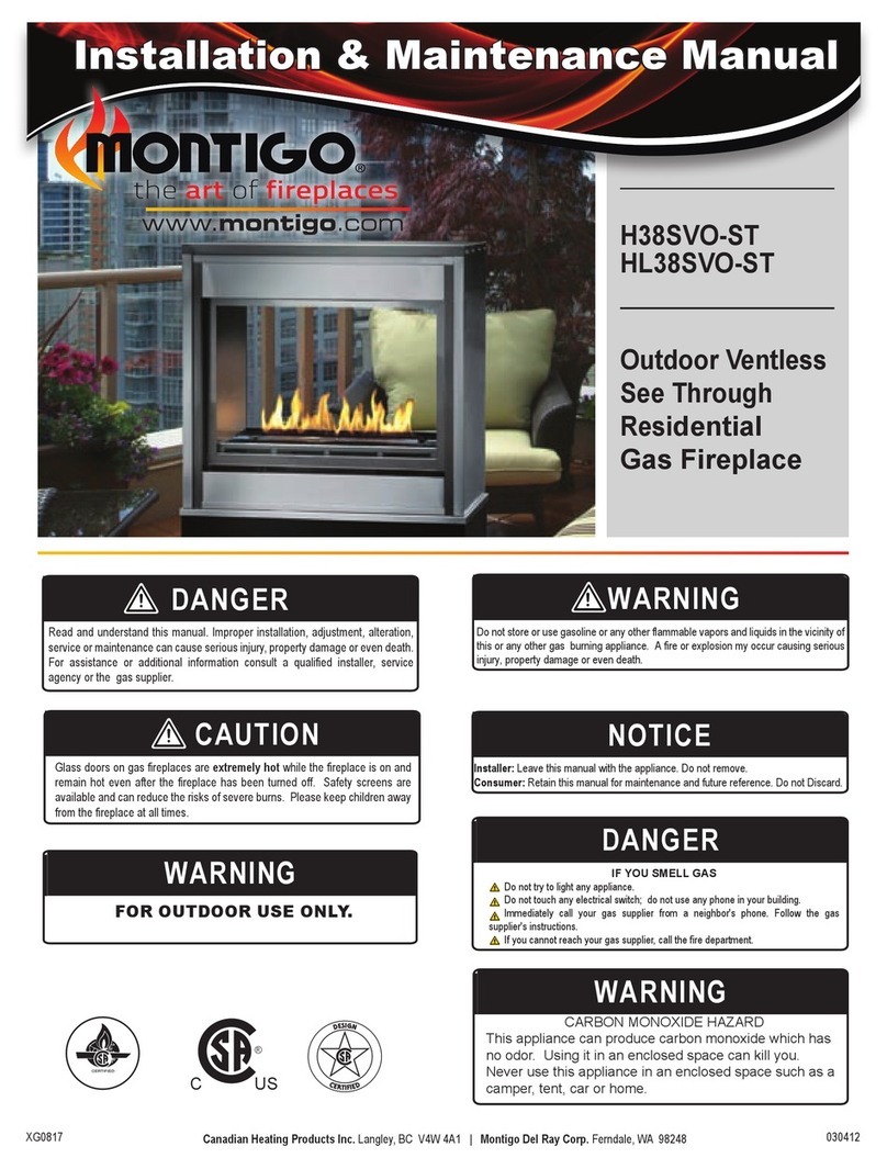
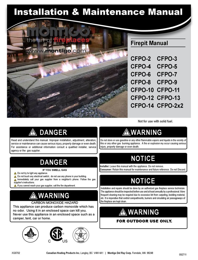
Montigo CFPO-3 Instruction Manual

Firepit Manual
CFPO-2 CFPO-3
CFPO-4 CFPO-5
CFPO-6 CFPO-7
CFPO-8 CFPO-9
CFPO-10
XG0702 092711
Canadian Heating Products Inc. Langley, BC V4W 4A1 | Montigo Del Ray Corp. Ferndale, WA 98248
Not for use with solid fuel.
®
C US
Read and understand this manual. Improper installation, adjustment, alteration,
service or maintenance can cause serious injury, property damage or even death.
For assistance or additional information consult a qualified installer, service
agency or the gas supplier.
DANGER
Do not store or use gasoline or any other flammable vapors and liquids in the vicinity of
this or any other gas burning appliance. A fire or explosion my occur causing serious
injury, property damage or even death.
WARNING
Installer: Leave this manual with the appliance. Do not remove.
Consumer: Retain this manual for maintenance and future reference. Do not Discard.
NOTICE
IF YOU SMELL GAS
Do not try to light any appliance.
Do not touch any electrical switch; do not use any phone in your building.
Immediately call your gas supplier from a neighbor's phone. Follow the gas
supplier's instructions.
If you cannot reach your gas supplier, call the fire department.
DANGER
Irritant
Cutting
Watchyour step
Slipperyfloor
Hightemperatures
Glasshazard
Dangerof suffocation
Highvoltage
Toxic
Flammablematerials
Corrosive
Forklift trucks
Dangeroverhead crane
Explosionrisk
Oxidising
Dangerof death
Biohazard
LaserRadiation
Dangerof entrapment
Hotsurface
GeneralWarning
Blank
Gasbottles
Watchfor
fallingobjects
Electricity
Dangerfor cutter
Entrapmenthazard
Batteryhazard
Rotatingparts
Lowtemperature
Strongmagnetic field
Opticalradiation
Nonionizing
radiation
Radiation
Hazardousto the
Environment
Dangerof harming
yourhands
Irritant
Cutting
Watchyour step
Slipperyfloor
Hightemperatures
Glasshazard
Dangerof suffocation
Highvoltage
Toxic
Flammablematerials
Corrosive
Forklift trucks
Dangeroverhead crane
Explosionrisk
Oxidising
Dangerof death
Biohazard
LaserRadiation
Dangerof entrapment
Hotsurface
GeneralWarning
Blank
Gasbottles
Watchfor
fallingobjects
Electricity
Dangerfor cutter
Entrapmenthazard
Batteryhazard
Rotatingparts
Installation and repairs should be done by an authorized gas fireplace service technician.
The appliance should be inspected before use and at least annually by a professional. More
frequent cleaning may be required due to excessive lint from carpeting, bedding material,
etc. It is imperative that control compartments, burners and circulating air passageways of
the fireplace are kept clean.
NOTICE
WARNING
CARBON MONOXIDE HAZARD
This appliance can produce carbon monoxide which has
no odor. Using it in an enclosed space can kill you.
Never use this appliance in an enclosed space such as a
camper, tent, car or home.
WARNING
FOR OUTDOOR USE ONLY.
Installation & Maintenance Manual

Introduction.......................................................................................3
Installation.........................................................................................4
Section 1: General Information..................................................4
Section 2: Unit Specications....................................................4
Section 3: Installation Location.................................................5
Clearances to Surrounding Construction ...................................5
Section 4: Unit Dimensions........................................................6
Section 5: Framing and Finishing .............................................6
Section 6: Combustion Air Supply ............................................7
Section 7: Electrical Control Panel............................................8
Section 8: Electrical Connections ...........................................10
Installing the Control Panel ......................................................10
Section 9: Installing the Gas Line............................................ 11
Section 10: Installing the Burner Accessories.......................12
Installing the Firestones ...........................................................12
Operation.........................................................................................13
Section 11: Start-Up ..................................................................13
Maintenance....................................................................................14
Section 12: General Maintenance and Cleaning ....................14
Annual Inspection Checklist .....................................................14
Section 13: Troubleshooting....................................................15
Appendix .........................................................................................16
Appendix A - Warranty..............................................................16
Appendix B - State of Massachusetts..................................... 17
Page 2
Table of Contents
Custom C-View Fireplace
XG0702
You must read and understand this manual prior to installation, operation or
troubleshooting this appliance. Please retain this owner’s manual for future reference
and maintenance.
NOTICE

Page 3
Indicates a hazardous situation which, if not
avoided, WILL result in death or serious
injury or property damage.
Indicates a hazardous situation which, if not
avoided, COULD result in death or serious
injury or property damage.
Indicates a hazardous situation which, if not
avoided, WILL result in minor or moderate
injury.
Addresses practices that are important, but
not related to personal injury
DANGER WARNING
CAUTION NOTICE
Custom C-View Fireplace
Safety Alert Key
XG0702
Congratulations on your purchase of a Montigo Firepit.
With over 30 years of experience, Montigo is committed to provid-
ing you with a gas appliance that is not only a beautiful addition
to your space, but that is also designed and manufactured to the
highest safety, reliability and engineering standards.
We strongly encourage you to read and carefully follow the in-
structions laid out in this Installation, Operation and Maintenance
Manual and retain it for your future reference. Pay special atten-
tion to all cautions, warnings, and notices throughout this manual
intended to ensure your safety.
This manual covers installation, operation and maintenance.
Lighting, operation and care of this replace can be easily per-
formed by the end user. All installation and service work should
be performed by a qualied or licensed installer, plumber or gas
tter as certied by the state, province, region or governing body
where the replace is being installed.
This installation, operation and maintenance manual is applicable
to the models described below. Refer to your rating plate to verify
included options.
Warranty and Installation Information (aee Appendix A)
The Montigo warranty will be voided by, and Montigo disclaims
any responsibility for, the following actions:
► Modication of the repit and/or components.
► Use of any component part not manufactured or
approved by Montigo in combination with this Montigo repit
system.
► Installation other than as instructed in this manual.
Consult your local Gas Inspection Branch on installation require-
ments for factory-built gas replaces. Installation & repairs should
be done by a qualied contractor.
Installations in Canada must conform to the current CAN/CGA
B-149.1 and .2 Gas Installation Code and local regulations.
This appliance must be electrically grounded in accordance
with CSA C22.1 Canadian Electrical Code Part 1 and/or Lo-
cal Codes. See Appendix B for installation within the State
of Massachusetts.
Introduction

Model Maximum Gas Input (NG or LP) BTU/hr
CFPO-2 22,000
CFPO-3 40,000
CFPO-4 60,000
CFPO-5 80,000
CFPO-6 90,000
CFPO-7 110,000
CFPO-8 130,000
CFPO-9 150,000
CFPO-10 170,000
Figure 1: Max. Gas Input
Planning for the Installation of your Custom Montigo Firepit
This Installation, Operation and Maintenance guide is specic to your Custom Montigo Firepit. Please
read through this entire manual and adhere to all warnings and notices.
Please follow these guidelines for a successful installation:
• Firepits must be located outdoors
• We recommend that the unit be placed in an area that is not covered, however if you wish to place
it in a covered area there are strict guidelines that must be adhered to in Section 3
• Place the unit in a location that is least affected by wind
• Firepits have an open ame that can cause injury. Consider the safety of children and other indi-
viduals during placement
• Montigo requires that all framing in direct contact with the unit be of non-combustible construction
• Ensure that access is available to make gas and electrical connections and for future service. We
recommend using the Fresh Air Supply Grille for this access.
• If this unit is exposed to rain/snow, include drainage holes at the base of the walls of your enclo-
sure
Section 1: General Information
Section 2: Unit Specications
Page 4 XG0702
C-View Custom Fireplace
Installation

Section 3: Installation Location
Montigo reccommends that you install the Custom
C-View Firepit in an exterior area that is not cov-
ered. This will ensure no collection of off gases.
Should you be installing the repit in a covered
area, you must abide by the following requirements.
en
en
Acceptable Installation 1
Install Firepit under a covered area with 3 sides open
en
Acceptable Installation 2
Install Firepit under a covered area with 2 sides open
Acceptable Installation 3
For covered area installations where less than 2 sides
will be fully open, there must be one side open such
that there is 10 square feet of fresh air per 20,000 BTU
of your unit. Also you must install a Montigo interlocking
carbon monoxide detector in the furthest location from
the opening. (Part No. EBOX-A310)
Fig 2: Covered Installation Option 1
Fig 3: Covered Installation Option 2
Fig 4: Covered Installation Option 3
Clearances to Surrounding Construction
Clearances to the ceiling of the space and to adjacent walls must meet requirements shown below:
Wall
Model Y Y1
CFPO-2 6' 7'
CFPO-3 7' 8'
CFPO-4 8' 9'
CFPO-5 9' 10'
CFPO-6 10' 11'
CFPO-7 11' 12'
CFPO-8 12' 13'
CFPO-9 13' 14'
CFPO-10 14' 15'
Fig 5: Clearance to Surrounds
Page 5
XG0702
Custom C-View Fireplace
Installation

Section 4: Unit Dimensions
C
D
H
G
F
E
A
B
Model A B C D E F G H
CFPO-2 23.5" 11.88" 24.125" 28" 12" 15.88" 12" 0.625"
CFPO-3 35.5" 11.88" 36.125" 40" 12" 15.88" 12" 0.625"
CFPO-4 47.5" 11.88" 48.125" 52" 12" 15.88" 12" 0.625"
CFPO-5 59.5" 11.88" 60.125" 64" 12" 15.88" 12" 0.625"
CFPO-6 71.5" 11.88" 72.125" 76" 12" 15.88" 12" 0.625"
CFPO-7 83.5" 11.88" 84.125" 88" 12" 15.88" 12" 0.625"
CFPO-8 95.5" 11.88" 96.125" 100" 12" 15.88" 12" 0.625"
CFPO-9 107.5" 11.88" 108.125" 112" 12" 15.88" 12" 0.625"
CFPO-10 119.5" 11.88" 120.125" 124" 12" 15.88" 12" 0.625"
C
D
H
G
F
E
A
B
This unit is designed to sit in a non-combustible surround.
The repit must be supported from underneath by non-combus-
tible framing spaced no more than two feet apart.
Do not support the repit by its surrounding lip. Additionally,
ensure that all surrounding materials are non-combustible, or
follow the clearances to combustibles given in this manual.
The inner dimensions of your surround framing are recom-
mended to be Dimension G (Fig. 6) plus 1 inch by Dimension C
(Fig. 6) plus 1 inch. This will give you enough room to maneu-
ver the repit into place.
There must be a minimum of 3 inches below the unit so that
fresh air can circulate.
Section 5: Framing and Finishing
Fig 6: Unit Dimensions
Clearances
Sides 2"
Back N/A
Mantel N/A
Top N/A
Floor 3"
The following clearances to combustibles must be main-
tained to the Custom Firepit:
Fig 7: Clearances
Page 6 XG0702
C-View Custom Fireplace
Installation

There must be an unobstructed fresh air supply grille lo-
cated in the lower portion of the surround below the repit.
The size of this grille must meet the requirements laid out
in the table below. This grille should also act as access to
the gas connection shut-off valve.
Model Size of Grille (sq in.)
CFPO-2 3.33
CFPO-3 6.66
CFPO-4 10.00
CFPO-5 13.33
CFPO-6 16.67
CFPO-7 20.00
CFPO-8 23.33
CFPO-9 26.65
CFPO-10 30.00
Section 6: Combustion Air Supply
Fresh Air Supply Grille
Fig 9: Fresh Air Supply Grille
Non-Combustible
Surround
Fig 8: Framing Diagram
Gas In
Fresh Intake Air
Min. 3" From Bottom of
Cross Supports to Floor
(6" Clearance Shown
Here)
1" Min. Clearance to Non-Combusti-
ble Materials All Around
4" x 18" Screened Opening
Shown Here
Do Not Install Cross Supports Directly
In Line with Intake Holes. Holes MUST
Remain Unobstructed
Firepit Lip MUST NOT Bear Any
Weight. It is ONLY For Covering the
Gap Between Firepit and Surround
Page 7
XG0702
Custom C-View Fireplace
Installation

MCP1-FIREPIT
Electrical Control Panel for Custom Firepit
01/08/15
INVENTORY
QTY. PartNo. Descripon
1 EC1142 Transformer, Class 2 - Input: 110VAC 60Hz - Output: 24VAC 1.875A 40VA
1 EC2046 Toggle Switch
1 EC1129 Power cord 18/3C, straight plug
SPECIFICATIONS
Enclosure Material: Weatherght PVC
Power Supply: Single Phase 110 Volt AC, 5 Amp NEMA 5-15P
Power Output from Transformer: 24VAC, 40VA Max
Gas
Valve
Firepit On/Off Switch
Plug
Black
Black Red
Red
Black
White
Green
110V
24V
6.375"
7.875"
8.5"
8.5"
4.625"
Page 1 of 2
Replacement Parts available from your local Montigo dealer
Section 7: Electrical Control Panel
This control panel will be used for units with 1 gas valve including: CFPO-2, CFPO-3, CFPO-4, CFPO-5, CFPO-6,
CFPO-7, CFPO-8
Fig 10: Control Panel Schematics (1 valve)
Page 8 XG0702
C-View Custom Fireplace
Installation

MCP2-FIREPIT
Electrical Control Panel for Custom Firepit
07/18/16
INVENTORY
QTY. PartNo. Descripon
2 EC1142 Transformer, Class 2 - Input: 110VAC 60Hz - Output: 24VAC 1.875A 40VA
1 EC2046 Toggle Switch
1 EC1129 Power cord 18/3C, straight plug
SPECIFICATIONS
Enclosure Material: Weatherght PVC
Power Supply: Single Phase 110 Volt AC, 5 Amp NEMA 5-15P
Power Output from Transformers: 24VAC, 40VA Max
Gas
Valve 1
Firepit On/Off Switch
Plug
110V
24V
24V 110V
Gas
Valve 2
Black
Black
Red
Red
Black
White
Green
Brown
Red
6.375"
7.875"
8.5"
8.5"
4.625"
Page 1 of 2
Replacement Parts available from your local Montigo dealer
This control panel will be used for units with 2 gas valve including: CFPO-9, CFPO-10 and larger custom sizes
Fig 11: Control Panel Schematics (2 valves)
Page 9
XG0702
Custom C-View Fireplace
Installation

Section 8: Electrical Connections
MCP1-FIREPIT
Electrical Control Panel for Custom Firepit
01/08/15
CAUTION
Disconnect power before performing any work on this control panel
ELECTRICAL CONNECTION DIRECTIONS
1.
The repit control panel comes pre-wired to the replace and all internal components. If the cables that connect the panel to the
replace need to be disconnected in order to be run inside of a conduit or raceway, follow the aached schemac to re-connect
the wiring.
2. Mount the control box in an appropriate locaon before operang the repit.
3. Plug the control panel’s power cord into a standard 120V outlet connected to an adequately sized circuit.
Page 2 of 2
FIREPIT OPERATION
1. Ensure all gas and electrical connecons are made.
2. Turn the repit on with the toggle switch mounted on the side of the control panel.
3. The control panel will supply power to the Honeywell smart valve. The glow plug will light the pilot and establish a pilot ame. The
pilot ame is recognized by the ame sensor rod and sends a signal to the valve to open the main burner. Any distoron of the
ame paern will give the valve a faulty signal and turn the main burner o. If the air movement of the system is too errac, the air
may move the pilot ame from the sensor rod and turn the valve o. Aer a pilot failure, the valve will connue to light the pilot
two mes, and then go into a 5 minute lockout mode. To reset the smart valve, simply turn the toggle switch o and then back on.
CAUTION
Make sure that all of the air is purged out of the gas lines
Installing the Control Panel
The control panel should be installed in a location that is accessible for start up and future service. The inverter may
sometimes produce a whining sound, this should be considered when selecting the panel location. Should the noise from
the panel be a concern, we recommend that the box containing the panel be lined with a sound proong material.
Page 10 XG0702
C-View Custom Fireplace
Installation

Note: After the gas line is connected, each appliance connection,valve and valve train must be checked while
under normal operating pressure with either a liquid solution, or leak detection device, to locate any source of
leak. Tighten any areas where bubbling appears or where a leak is detected until bubbling stops completely
or leak is no longer detected. DO NOT use a ame of any kind to test for leaks.
B k
R
W
Inlet Pressure
Check Manifold
Pressure
Check
Section 9: Installing the Gas Line
For Your Safety - READ BEFORE LIGHTING:
Immediately call your gas supplier from a neighbour's
phone. Follow the gas supplier's instructions.
If you cannot reach your gas supplier, call the Fire De-
partment.
C. Do not use this appliance if any part has been under water.
Immediately call a qualied service technician to inspect the
appliance and to replace any part of the control system, and
any gas control which has been under water.
A. This appliance is equipped with an ignition system that lights
the pilot burner automatically. Do not attempt to light the
pilot by hand.
B. BEFORE LIGHTING smell all around the appliance area for
gas. Be sure to smell next to the oor because some gas is
heavier than air and will settle on the oor.
What To Do If You Smell Gas:
Do not try to light any appliance.
Do not touch any electrical switch; do not use any phone
in your building.
WARNING! If you do not follow these instructions exactly, a re or
explosion may result causing property damage, personal injury or loss of life.
The gas connection is located on the underside of the repit body. The manufacturer requires a service shut off valve lo-
cated in an accessible location to isolate the replace’s gas supply. We reccommend placing this behind your intake grate
for easy access.The gas line must be installed, and tested for leaks before nishing the Custom Firepit.
Natural Gas requires a minimum inlet gas supply pressure of 5.5" wc, and a manifold pressure of 3.5" wc.
Propane requires a minimum inlet gas supply pressure of 11" wc, and a manifold pressure of 10" wc.
Maximum inlet pressure is 1/2 PSI for both NG and Propane.
The manifold outlet pressure is set from the factory to the appropriate pressure and should be veried. The control valves
have a provision to remove a 1/8 " plug so that a hose barb tting can be installed to check pressure.
Fig 13: Gas Connection Location
*6" vent height recommended for ease of access but
not required
6" *
Fig 12: Gas Valve
Page 11
XG0702
Custom C-View Fireplace
Installation

Section 10: Installing the Burner Accessories
If the restones are not placed properly (ONE LAYER
ONLY) on burners, excessive sooting will result. The re-
stones will get very hot while the replace is in operation,
and should not be handled until cool.
Installing the Firestones
The Montigo Custom Firepit with Concealed Burner is
supplied with restone glass media. Place the restones
randomly across the pan and the burners as described in
Figure 14 to 14d.
Note: Only cover the burner with one layer of designer re-
stones.
Figure 14 Installation of the restones. (Ensure ONLY one
layer of restones cover the surface).
Figure 14a Spreading the restones evenly and make sure
there are no restones covering the pilot .
Figure 14b Completed restone installation.
Figure 14c Completed restone installation. (Note: DO
NOT place ANY restones on top of the pilot cover).
Figure 14d Gas replace with restones covering burner
tray.
CAUTION!
Page 12 XG0702
C-View Custom Fireplace
Installation

Section 11: Start-Up
MCP1-FIREPIT
Electrical Control Panel for Custom Firepit
01/08/15
CAUTION
Disconnect power before performing any work on this control panel
ELECTRICAL CONNECTION DIRECTIONS
1. The repit control panel comes pre-wired to the replace and all internal components. If the cables that connect the panel to the
replace need to be disconnected in order to be run inside of a conduit or raceway, follow the aached schemac to re-connect
the wiring.
2. Mount the control box in an appropriate locaon before operang the repit.
3. Plug the control panel’s power cord into a standard 120V outlet connected to an adequately sized circuit.
Page 2 of 2
FIREPIT OPERATION
1. Ensure all gas and electrical connecons are made.
2. Turn the repit on with the toggle switch mounted on the side of the control panel.
3.
The control panel will supply power to the Honeywell smart valve. The glow plug will light the pilot and establish a pilot ame. The
pilot ame is recognized by the ame sensor rod and sends a signal to the valve to open the main burner. Any distoron of the
ame paern will give the valve a faulty signal and turn the main burner o. If the air movement of the system is too errac, the air
may move the pilot ame from the sensor rod and turn the valve o. Aer a pilot failure, the valve will connue to light the pilot
two mes, and then go into a 5 minute lockout mode. To reset the smart valve, simply turn the toggle switch o and then back on.
CAUTION
Make sure that all of the air is purged out of the gas lines
Page 13
XG0702
Custom C-View Fireplace
Operation

Annual Inspection Checklist
1. Inspect the operation of the ame safety system (Honeywell HSI, ame rod, and ground electrode).
2. Inspect and ensure the lighting of the main burner occurs within 4 seconds of the main gas valve opening.
Inspect primary air openings for blockage.
3. Inspect condition of fresh air grille for obstruction and correct if present.
4. Vacuum and clean any debris in the rebox that is not supposed to be there.
5. Test and measure the ame failure response time of the ame safety system. It must de-energize the safety
shutoff in no more than 30 seconds.
6. Check all accessible gas-carrying tubes, connections, pipes and other components for leaks.
Section 12: General Maintenance and Cleaning
CAUTION!
Fireplace gas control must be in the “OFF” position and all burners extinguished when cleaning appliance
General
Have the repit installation inspected yearly, including a visual check of the vent system, the burner and the pilot
ame. For your convenience a 1/8 " manifold pressure tap is supplied on the gas valve for a test gauge connec-
tion.
For Natural Gas this appliance requires a minimum inlet pressure of 5.5" wc, and a manifold pressure of 3.5"
wc.
For Propane this appliance requires a minimum inlet pressure of 11" wc, and a manifold pressure of 10" wc.
Always keep the repit area clear and free of combustible materials, as well as gasoline and other ammable
vapours and liquids.
Do not use this appliance if any part has been under water. Immediately call a qualied service technician to
inspect the appliance and to replace any part of the control system and any gas control which has been under
water.
Use a vacuum cleaner or whisk broom to keep the control compartment, burner, and rebox free from dust and
lint.
Page 14 XG0702
C-View Custom Fireplace
Maintenance

Inverter displays and power indicator light up
Power up the Mongo control panel
Yes
No • Blown fuse
• Incorrect supply voltage
Turn wall switch on
Yes
• Combuson air relay on
• Power vent starts up
No • Restricted air intake
• Power vent not connected
Flue gas relay on
Yes
No • Increase power vent speed
• Reverse power vent direcon
Flue gas relay on
No
Contact Mongo Tech Support
Yes
1 minute system purge
Smart valve relay on
Hot surface igniter glows
No
Yes
• Pressure switch trip
• Failed purge mer
Yes
Pilot ame lights
No • Control cable not connected
• Pilot assembly failure
• Smart valve failure
No
• Air in gas line
• Gas not turned on
Yes
• Igniter o
• Smart valve opens
• Main burner lights
No • Pilot not touching ame rod
• Poor ground connecon
Turn wall switch o
• Fireplace burner o
• Power vent purges for 3 minutes
Power vent o
C-VIEW Sequence of Operaon
Section 13: Troubleshooting
Page 15
XG0702
Custom C-View Fireplace
Maintenance

The Warranty
The Companies warrants the Montigo Gas Appliance to be free from defects in materials and workmanship at the time of manufacture. On the Montigo, there is a ten-
year warranty on the rebox and its components, a ve-year warranty on the main burner, and a one-year warranty on the pilot burner, gas control valve and bre logs.
Glass, plated/painted nishes, and refractory lining are exempt.
Remedy And Exclusions
The coverage of this Warranty is limited to all components of the Gas Appliance manufactured by The Companies.
This Warranty only covers Montigo Gas Appliances installed in the United States or Canada.
If the components of the Gas Appliance covered by this Warranty are found to be defective within the time frame stated (see The Companies right of investigation
outlined below). The Companies will, at its option, replace or repair defective components of the Gas Appliance manufactured by The Companies at no charge, and
will also pay for reasonable labour costs incurred in replacing or repairing components. If repair or replacement is not commercially practical, The Companies will, at its
option, refund the purchase price of the Montigo Gas Appliance.
This Warranty covers only parts and labour as provided above. In no case shall The Companies be responsible for materials, components, or construction which are
not manufactured or supplied by The Companies, or for the labour necessary to install, repair or remove such materials, components or construction. All replacement
or repair components will be shipped F.O.B. the nearest The Companies factory.
Qualications To The Warranty
The Gas Appliance Warranty outlined above is further subject to the following qualications:
(1) The Gas Appliance must be installed in accordance with The Companies installation instructions and local building codes. The Warranty on this Montigo Gas
Appliance covers only the component parts manufactured by The Companies. The use of components manufactured by others with this Montigo Gas Appliance
could create serious safety hazards, may result in the denial of certication by recognized national safety agencies, and could be in violation of local building codes.
This warranty does not cover any damages occurring from the use of any components not manufactured or supplied by The Companies
(2) The Montigo Gas Appliance must be subjected to normal use. The Gas Appliances are designed to burn gas only. Burning conventional replace fuels such as
wood, coal or any other solid fuel will cause damage to the Gas Appliance, will produce excessive temperatures and will result in a re hazard.
Limitations On Liability
It is expressly agreed and understood that The Companies sole obligation, and purchaser's exclusive remedy under this Warranty, under any other warranty, expressed
or implied, or in contract, tort or otherwise, shall be limited to replacement, repair, or refund, as specied above.
In no event shall The Companies be responsible for any incidental or consequential damages caused by defects in its products, whether such damage occurs or is
discovered before or after replacement or repair, and whether or not such damage is caused by The Companies negligence. Some states do not allow the exclusion
or limitation of incidental or consequential damages, so the above limitation or exclusion may not apply to you. The duration of any implied warranty with respect to
this Montigo Gas Appliance is limited to the duration of the foregoing warranty. Some states do not allow limitation on how long an implied warranty lasts, so the above
may not apply to you.
Investigation Of Claims Against Warranty
The Companies reserves the right to investigate any and all claims against this Warranty and to decide upon method of settlement.
The Companies Are Not Responsible For Work Done Without Written Consent
The Companies shall in no event be responsible for any warranty work done without rst obtaining The Companies written consent.
Dealers Have No Authority To Alter This Warranty
The Companies employees and dealers have no authority to make any warranties nor to authorize any remedies in addition to or inconsistent with those stated above.
How To Register A Claim Against Warranty
In order for any claim under this Warranty to be valid, The Companies must be notied of the claimed defect in writing or by telephone, as soon as reasonably possible
after the defect is discovered. Claims against this Warranty in writing should include the date of installation, and a description of the defect.
Other Rights
This Warranty gives you specic legal rights, and you may also have other rights which vary from state to state.
NOTE: The Companies as stated above refer to - Canadian Heating Products Inc. and/or Montigo Del Ray Corp.
Canadian Heating Products Inc. and/or Montigo DelRay Corp. reserves the right to make changes at any time, without notice, in design, materials,
specications, prices and also to discontinue colors, styles and products.
Appendix A - Warranty
Page 16 XG0702
C-View Custom Fireplace
Appendix

Amendment
(Gas Fireplace / Equipment sold in the State of Massachusetts)
5.08: Modications to NFPA-54, Chapter 10
(1) Revise NFPA-54 section 10.5.4.2 by adding a second exception as follows:
Existing chimneys shall be permitted to have their use continued when a gas conversion burner is installed, and shall be equipped with a manually reset device that
will automatically shut off the gas to the burner in the event of a sustained back-draft.
(2) Revise 10.8.3 by adding the following additional requirements:
(a) For all side wall horizontally vented gas fueled equipment installed in every dwelling, building or structure used in whole or in part for residential purposes, includ-
ing those owned or operated by the Commonwealth and where the side wall exhaust vent termination is less than seven (7) feet above nished grade in the area of
the venting, including but not limited to decks and porches, the following requirements shall be satised:
1. INSTALLATION OF CARBON MONOXIDE DETECTORS. At the time of installation of the side wall horizontal vented gas fueled equipment, the
installing plumber or gas tter shall observe that a hard wired carbon monoxide detector with an alarm and battery back-up is installed on the oor level where the
gas equipment is to be installed. In addition, the installing plumber or gas tter shall observe that a battery operated or hard wired carbon monoxide detector with an
alarm is installed on each additional level of the dwelling, building or structure served by the side wall horizontal vented gas fueled equipment. It shall be the respon-
sibility of the property owner to secure the services of qualied licensed professionals for the installation of hard wired carbon monoxide detectors
a. In the event that the side wall horizontally vented gas fueled equipment is installed in a crawl space or an attic, the hard wired carbon monoxide detector with alarm
and battery back-up may be installed on the next adjacent oor level.
b. In the event that the requirements of this subdivision can not be met at the time of completion of installation, the owner shall have a period of thirty (30) days to
comply with the above requirements; provided, however, that during said thirty (30) day period, a battery operated carbon monoxide detector with an alarm shall be
installed.
2. APPROVED CARBON MONOXIDE DETECTORS. Each carbon monoxide detector as required in accordance with the above provisions shall
comply with NFPA 720 and be ANSI/UL 2034 listed and IAS certied.
3. SIGNAGE. A metal or plastic identication plate shall be permanently mounted to the exterior of the building at a minimum height of eight (8) feet
above grade directly in line with the exhaust vent terminal for the horizontally vented gas fueled heating appliance or equipment. The sign shall read, in print size no
less than one-half (1/2) inch in size, “GAS VENT DIRECTLY BELOW. KEEP CLEAR OF ALL OBSTRUCTIONS”.
4. INSPECTION. The state or local gas inspector of the side wall horizontally vented gas fueled equipment shall not approve the installation unless, upon
inspection, the inspector observes carbon monoxide detectors and signage installed in accordance with the provisions of 248 CMR 5.08(2)(a)1 through 4.
(b) EXEMPTIONS: The following equipment is exempt from 248 CMR 5.08(2)(a)1 through 4:
1. The equipment listed in Chapter 10 entitled “Equipment Not Required To Be Vented” in the most current edition of NFPA 54 as adopted by the Board;
and
2. Product Approved side wall horizontally vented gas fueled equipment installed in a room or structure separate from the dwelling, building or structure
used in whole or in part for residential purposes.
(c) MANUFACTURER REQUIREMENTS - GAS EQUIPMENT VENTING SYSTEM PROVIDED. When the manufacturer of Product Approved
side wall horizontally vented gas equipment provides a venting system design or venting system components with the equipment, the instructions provided by the
manufacturer for installation of the equipment and the venting system shall include:
1. Detailed instructions for the installation of the venting system design or the venting system components; and
2. A complete parts list for the venting system design or venting system.
(d) MANUFACTURER REQUIREMENTS - GAS EQUIPMENT VENTING SYSTEM NOT PROVIDED.When the manufacturer of a Product Ap-
proved side wall horizontally vented gas fueled equipment does not provide the parts for venting the ue gases, but identies “special venting systems”, the following
requirements shall be satised by the manufacturer:
1. The referenced “special venting system” instructions shall be included with the appliance or equipment installation instructions; and
2. The “special venting systems” shall be Product Approved by the Board, and the instructions for that system shall include a parts list and detailed
installation instructions.
(e) A copy of all installation instructions for all Product Approved side wall horizontally vented gas fueled equipment, all venting instructions, all parts lists for venting
instructions, and/or all venting design instructions shall remain with the appliance or equipment at the completion of the installation.
(3) After NFPA-54 section 10.10.4.2 add a new section 10.10.4.3 as follows:
When more than four gas appliances are to be vented through a common gas vent or common horizontal vent manifold, a plan of the proposed vent installation shall
be submitted to the Inspector and the serving gas supplier for review and approval.
Extraction from: Massachusets Rules and Regulations
5.00: Amendments To 2002 Edition Of ANSI Z223.1-NFPA-54
Appendix B - State of Massachusetts
Page 17
XG0702
Custom C-View Fireplace
Appendix

Ferndale, Washington
TF: 1.800.789.6236
FX: 1.866.3000.0927
XG702 - 092711
Langley, British Columbia
TF: 1.800.378.3115
FX: 1.604.607.6462
CFPO Custom
Outdoor Firepit
This manual suits for next models
8
Table of contents
Other Montigo Outdoor Fireplace manuals

Montigo
Montigo Homefire ME38-ODV-2 User manual

Montigo
Montigo CabanaFire PL42VO Instruction Manual

Montigo
Montigo H34VO Instruction Manual

Montigo
Montigo CFPO-2 Instruction Manual

Montigo
Montigo M38ODV-ST User manual

Montigo
Montigo H38SVO-ST Series Instruction Manual

Montigo
Montigo HL38SVO Series Instruction Manual
Popular Outdoor Fireplace manuals by other brands

Cosi
Cosi 5980940 User and installation instructions

hillvert
hillvert HI-FIP-001 user manual

EcoSmart Fire
EcoSmart Fire Bulb Clearances & Installation Manual

Planika
Planika Galio Star Corten Installation and user manual

Petromax
Petromax fs38 user manual

Kingsman Fireplaces
Kingsman Fireplaces OFP42N OWNER'S OPERATION AND INSTALLATION MANUAL