Moog Tritech Super SeaKing 700 V7 Series User manual
Outstanding Performance in Underwater Technology A Moog Inc. Company
Super SeaKing 700 V7
Bathymetric Sensor
Product Manual
Document No-0688-SOM-00001
Rev2

This page has deliberately been left blank.

Help & Support
First please read this manual thoroughly (particularly the Troubleshooting section, if present). If a warranty is
applicable, further details can be found in the Warranty Statement, 0080-STF-00139, available upon request.
Tritech International Ltd can be contacted as follows:
Address Tritech International Ltd
Peregrine Road
Westhill Business Park
Westhill, Aberdeenshire
AB32 6JL, UK
Telephone +44(0)1224 744 111
Fax +44(0)1224 741 771
Email [email protected]
Website www.moog.com/tritech
Prior to contacting Tritech International Ltd please ensure that the following information is available:
1. The Serial Number of the product and any Tritech International Ltd equipment
connected directly or indirectly to it
2. Software or firmware revision numbers
3. A clear fault description
4. Details of any remedial action implemented
Contamination
If the product has been used in a contaminated or hazardous environment you
must de-contaminate the product and report any hazards prior to returning
the unit for repair. Under no circumstances should a product be returned that is
contaminated with radioactive material.
The name of the organisation which purchased the system is held on record at Tritech International Ltd and
information of new software or hardware packages will be announced at regular intervals. This manual may not
detail every aspect of operation and for the latest revision of the manual please refer to www.moog.com/tritech
Tritech International Ltd can only undertake to provide software support of systems loaded with the software in
accordance with the instructions given in this manual. It is the customer’s responsibility to ensure the compatibility
of any other package they choose to use.

Warning Symbols
Throughout this manual the following symbols may be used where applicable to denote any particular hazards
or areas which should be given special attention:
Note
This symbol highlights anything which would be of particular interest to the
reader or provides extra information outside of the current topic.
Important
When this is shown there is potential to cause harm to the device due to
static discharge. The components should not be handled without appropriate
protection to prevent such a discharge occurring.
Caution
This highlights areas where extra care is needed to ensure that certain delicate
components are not damaged.
Warning
DANGER OF INJURY TO SELF OR OTHERS. Where this symbol is present there is a
serious risk of injury or loss of life. Care should be taken to follow the instructions
correctly.
Copyright Notice.
The copyright in this document is the property of Tritech International Ltd. The document is supplied on the
understanding that it may not be copied, used, or disclosed to others except as authorised in writing by Tritech
International Ltd. We reserve the right to change, modify and update designs and specifications as part of our
ongoing product development programme.

Table of Contents
Introduction 1
Overview .................................................................................... 1
Technical Specifications.................................................... 2
Installations 4
Hardware Installation.......................................................... 4
Powering the Bathy............................................................. 5
Electrical Connections ....................................................... 5
Connecting an Altimeter.................................................. 5
Communications Configurations................................ 6
Ground fault Monitoring.................................................. 6
Wiring Diagrams.................................................................... 7
Wiring Pin-outs....................................................................... 8
Tritech V7 Connector.......................................................... 8
SeaNet Pro 9
Software Overview............................................................... 9
System Requirements ........................................................ 9
SeaNet Pro Software Installation................................. 9
Windows Setup....................................................................10
SeaNet Pro Setup ................................................................11
Magnetic Reset.....................................................................11
Device Conguration Window 12
Seanet Pro Operation.......................................................13
Main Screen............................................................................13
SeaNet Pro Tools ..................................................................14
System Configuration.......................................................16
Optimising the SK700 V7 17
System Check........................................................................17
Pre-dive Setup.......................................................................17
Recommended Pre-Dive checklist...........................18
Factors that affect measurement..............................19
Care and Maintenance 21
After using the Super Seaking 700...........................21
Seaking Basic Maintenance .........................................21
Field Service............................................................................21
Storage.......................................................................................21
Calibration ...............................................................................21
Appendix A 22
ARCNET Termination.........................................................22
Appendix B 23
Depth Derivation ...............................................................23
Default Depth Equation..................................................23
Gravity Formula....................................................................23
Alternative Depth Equation..........................................23
Salinity Equation..................................................................24
Density Equation.................................................................24
Appendix C 25
Chen & Millero Equation.................................................25
DelGrosso Equation...........................................................26
Wood Equation.....................................................................26
Mackenzie Equation.........................................................26
Wilson Equation..................................................................27
Coopers Equation..............................................................27
Medwin Equation..............................................................28
Leroy Equation......................................................................28

This page has deliberately been left blank.

1
0688-SOM-00001, Rev: 02 © Tritech International Ltd.
1. Introduction
1.1 Overview
The Super Seaking V7 series is built on a new platform, introducing an improved front end design, Ethernet
connectivity and software power isolation for AUX port output.
We have incorporated state of the art sensors to gather precision Sound Velocity and Density profiles for accurate
depth and height data. Pairing a V7 Seaking 700 with an altimeter and sonar from Tritech’s Seaking or Gemini
range gives a fully integrated oceanographic system which can be controlled from a single user interface and
easily integrated into any existing survey suit.
The V7 is a direct replacement for a V6 sonar with the exception of customers requiring Ethernet capability. This
will require either a proprietary Tritech ‘V7 connector’ or a compatible connector and cable harness. Arcnet and
Serial comms protocols are still supported.
Depth Accuracy
0.015%
Temperature Accuracy
±0.005˚C
Conductivity Accuracy
±0.3mS/m
of full scale depth
Features
• State-of-the-art sensor integration.
• New generation of algorithms.
• Software switchable Ethernet, ARCNET and
Serial Comms Protocols.
• Free running & interrogate modes.
• Simple integration to survey suites.
• Improved power efficiency.
Benets
• Higher accuracy real-time output for:
• Depth
• Temperature
• Conductivity
• Density
• Sound Velocity and
• Altitude
• Ease-of-use and integration.
• Robust performance for high-speed data
acquisition.
Applications
• ROV
• OCEANOGRAPHIC OPERATIONS
• METROLOGY
Related Products
PA500/6 Altimeter Super Seaking
V7 Sonar
Seaking Side Scan Gemini Multibeam
Sonars

2
0688-SOM-00001, Rev: 02 © Tritech International Ltd.
1.2 Technical Specifications
System Physicals Super Seaking 701 Series SSK704 Series
Weight in air (kg) 3.74 4.19
Weight in Water (kg) 1.44 1.69
Housing Material Anodised Aluminium Alloy
Depth Ratings 700m, 1400m, 2000m, 4000m
ø99
ø110
261
278
392
160
7241
ø47
ø43
303
Super Seaking 701
Super Seaking 704
Dimensions in millimetres.

3
0688-SOM-00001, Rev: 02 © Tritech International Ltd.
Electrical and Communication
Power Requirement Main 20-70VDC @ 8w
Aux Voltage set to 24VDC
Communications
SXXXXX nn ETH Main Ethernet & Serial RS232/RS485
Aux Serial RS232/RS485
SXXXXX nn ARC Main ARCNET & Serial RS232/RS485
Aux
Depth Sensor
Repeatability 0.01% FSD (Full Scale Depth)
Hysteresis 0.015% FSD
Drift 0.015% FSD
Temperature Sensor
Survey Grade Scientific Grade
Range -5˚C to 35˚C -5˚C to 35˚C
Accuracy ±0.01˚C ±0.005˚C
Drift ±0.002˚C per year ±0.005˚C per year
Conductivity Sensor
Survey Grade Scientific Grade
Range 0 to 8.5 S/m 0 to 8.5 S/m
Accuracy ±1.0mS/m ±0.3mS/m
Drift ±0.1mS/m per month ±0.1mS/m per month
Software Requirements Version Build
SeaNet Pro 2.24 548
Genesis (*Limited Functionality) 1.4.1
Altimeter Specifications
Type PA500
Weight in air 1150g
Weight in Water 800g
Frequency 500kHz
Beam width 6˚ conical
Range 0.3m to 50m
Resolution 1mm
Material Stainless Steel (Titanium 6AI4V optional)

4
0688-SOM-00001, Rev: 02 © Tritech International Ltd.
2. Installations
2.1 Hardware Installation
Mount the Seaking 700 using 3mm insulating rubber, and jubilee clamps to firmly secure
to the vehicle.
For accurate pressure measurement, the Seaking 700 Bathymetric sensor can be orientated
in a port up or port down configuration with calibrated offsets provided by the factory.
It’s recommended, during installation, that the bathy and altimeter be positioned so they
receive good water flow while avoiding prop-wash from thrusters.
It’s advisable that the conductivity sensor head should have a free radius of at least 10cm.
Objects within this must be electrically stable (either a fixed dielectric or conductor) and
have a fixed position relative to the sensor. Locate the sensor head away from items such
as motors, sense coils and cameras to ensure accurate readings.
Ensure the Seaking 700 is protected from the possibility of impact damage.
During Installation, be sure to safeguard against damage to the protective anodised
coating on the main housing. Any chips or scratches may lead to corrosion of the housing
which may impact the performance of the system.
Mate connectors/blanks ensuring the washers are in places and have been greased and
the securing screws have been tightened.
DO NOT OVER-TIGHTEN RETENTION SCREWS.
If using a Seacon connector, you are reminded that
the retention ring should be finger tight. Applying too
much pressure risks damaging the connector.
Check that the cables and connectors are not subjected to excessive strain and are not
kinked or bent excessively. The safe bend radius of the V7 cables is 100mm.
Caution
Non-metallic clamps are preferred when securing the
Bathy, however, if metallic clamps are to be used they
must be electrically insulated to protect the housing.
Avoid any clamping material that may
contain brass or bronze.
5
0688-SOM-00001, Rev: 02 © Tritech International Ltd.
2.2 Powering the Bathy
The SeaKing 700 Series units are designed to work from a smoothed DC power supply.
If using a rectified transformer PSU, the output of the PSU must have a filter capacitor of not less than 470μF, for
each unit being powered.
If an unregulated PSU is used, the voltage value measured during power on/off and running conditions at the
unit should be within the voltage range specified for the system.
If powering the unit(s) down a long lead or umbilical, the maximum recommended resistance of the power line
must not exceed 10Ω for one unit, 5Ω for two units and 3Ω for three units.
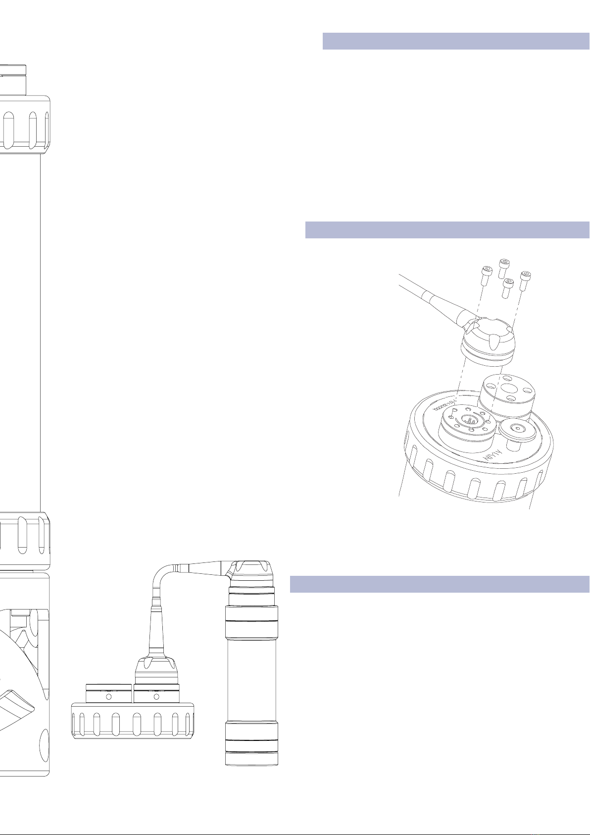
2.3 Electrical Connections
The SeaKing 700 is typically supplied with a 1meter polyurethane
jacketed cable whip, fitted with aTritech connector. Depending on the
specification of the system, the cable will either need to be terminated
to a suitable connector or may be supplied already terminated.
The standard Tritech connector may be disconnected from the unit
by unscrewing the four retaining screws and removing the connector
from the water block that is fitted to the end-cap. Do not remove the
water block.
While the cable is removed the exposed connectors should be fitted
with appropriate blanking caps to prevent the ingress of dirt or
moisture.
For devices fitted with non-Tritech connectors this procedure will vary.
For information on Tritech Standard wiring, connectors and pin-outs
please refer to Section 2.6 of this manual.
2.4 Connecting an Altimeter
The Bathy is designed to directly interface with a Tritech
PA500/06 altimeter. Connection is made to the Bathy Aux
Port using a standard Tritech double ended S01226 (R/A
to Str) interconnect cable.

6
0688-SOM-00001, Rev: 02 © Tritech International Ltd.
2.5 Communications Configurations
The V7 is a direct replacement for a V6 sonar with the exception of customers requiring Ethernet capability. This
will require either a proprietary Tritech ‘V7 connector’ or a compatible connector and cable harness. Arcnet and
Serial comms protocols are supported..
Seaking 700 Bathymetric sensors can be configured as Ethernet with Serial RS232/485 or as ARCNET and Serial
RS232/485 communication protocols. There is no ARCNET and Ethernet option.
See section on software setup for guidance on configuring your network.
Ethernet & Serial (RS232/RS485)
When connecting via Ethernet, the Bathy can communicate at 100Mbps while
returning environmental data.
If the Bathy shares it’s Ethernet link with other high bandwidth devices, such as
video cameras, it is recommended that a gigabit (or faster) network interface be
used to the surface to reduce possible network congestion.
Basic Ethernet Cable Setup
ARCNET & Serial (RS232/RS485)
The SeaKing 700 series can be set to form part of an ARCNET multidrop network
of sensors that are normally interfaced to a Surface Control Unit (SCU) through
an internal DA-15 ARCNET interface (AIF) port or through the DA-15 AIF port
on a SeaHub.
Normal communication with the Bathy head is via a customised version of the
ARCNET network system and requires a good quality balanced twisted pair.
There is also the option to run a single head from an RS232/RS485 connection.
Note
The ARCNET system requires termination resistors to be fitted at each end of
the umbilical. Please refer to Appendix A, ARCNET Termination for more details
of the termination requirements.
2.6 Ground fault Monitoring
The power supply within SeaKing subsea devices contain an electrically isolated
DC-DC converter. There is a small capacitive connection to the sonar chassis
which should not noticeably affect any impressed current ground fault indicator
(GFI) equipment.
PSU
S12102 XM SK V7 to 12w
Souriau Pwr / Ethernet Test Cable Xm
S11561 Gemini Power / Ethernet
Break-out Cable
S11346 Gemini Imaging Sonar
Power Supply Unit
7
0688-SOM-00001, Rev: 02 © Tritech International Ltd.
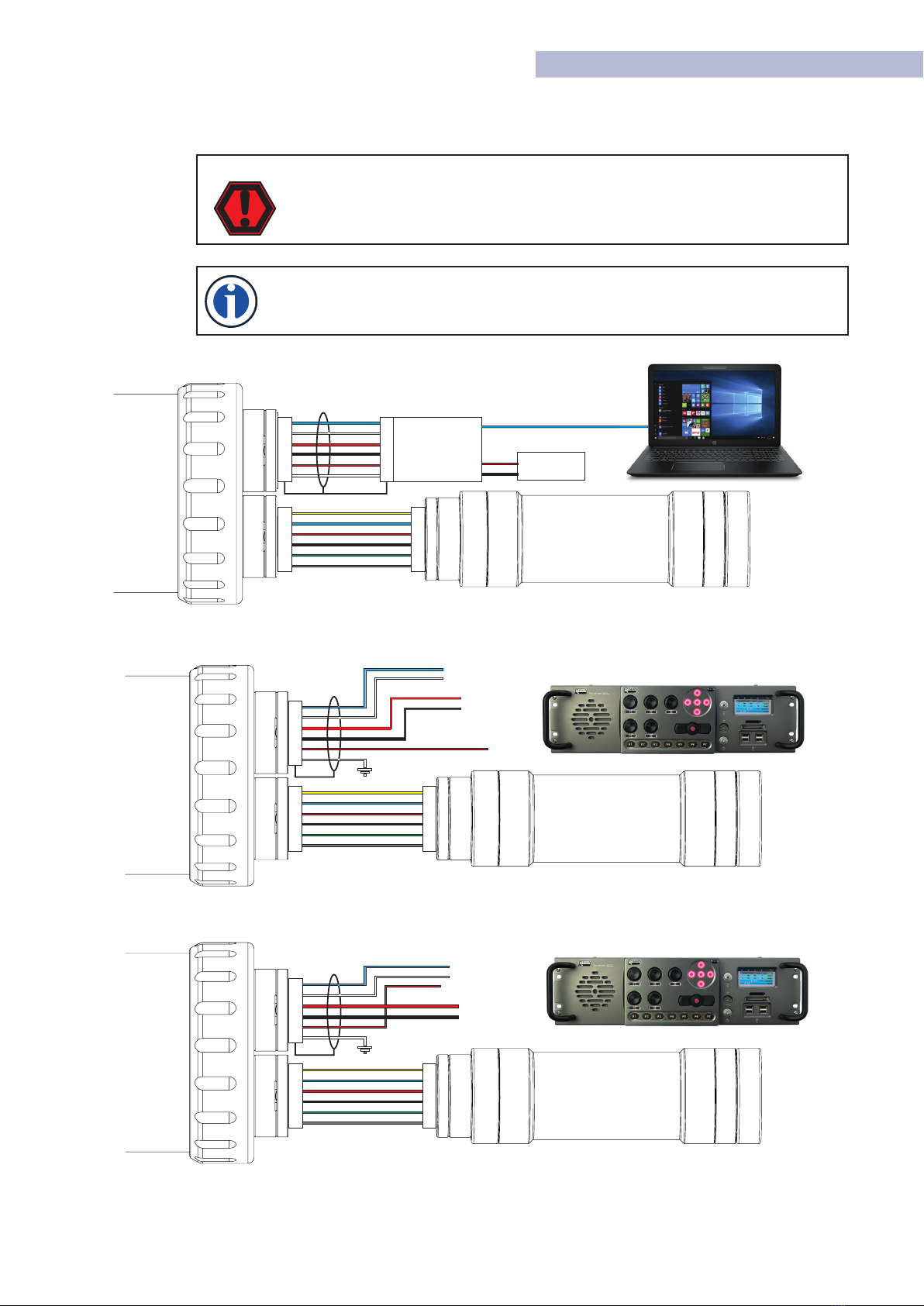
2.7 Wiring Diagrams
The below wiring diagrams refer to the standard Tritech connector, other connector options are available upon
request. Please contact our sales team for full details.
WARNING
Application of reverse supply voltage to the unit or supply voltage across any of
the communication connections may lead to equipment damage not covered
under the warranty conditions.
Note
Ethernet communications require the use of V7 cables. Other communications
modes are compatible with both V7 and Standard Tritech cables.
Ethernet Wiring.
ARCNET Wiring.
Serial RS232/485 wiring.
TX_P
TX_N
+VDC
0VDC
RX_N
RX_P
C
F
D
G
A
B
Breakout
PSU
RJ45
0 VDC
+VDC +VDC
0 VDC
1
2
3
4
5
6
1
2
3
4
5
6
1
2
3
4
5
6
Screen Pins
PA500/6
Altimeter
MAINAUX
1
2
3
4
5
6
1
2
3
4
5
6
N/C
PA500/6
Altimeter
SCU 5
MAINAUX
1
2
3
4
5
6
ARCNET A
ARCNET B
PSU
0 VDC
+VDC
SCU 5
1
2
3
4
5
6
1
2
3
4
5
6
1
2
3
4
5
6
PA500/6
Altimeter
MAINAUX
Serial RX
Serial TX
RS232 Gnd
PSU
0 VDC
+VDC
8
0688-SOM-00001, Rev: 02 © Tritech International Ltd.
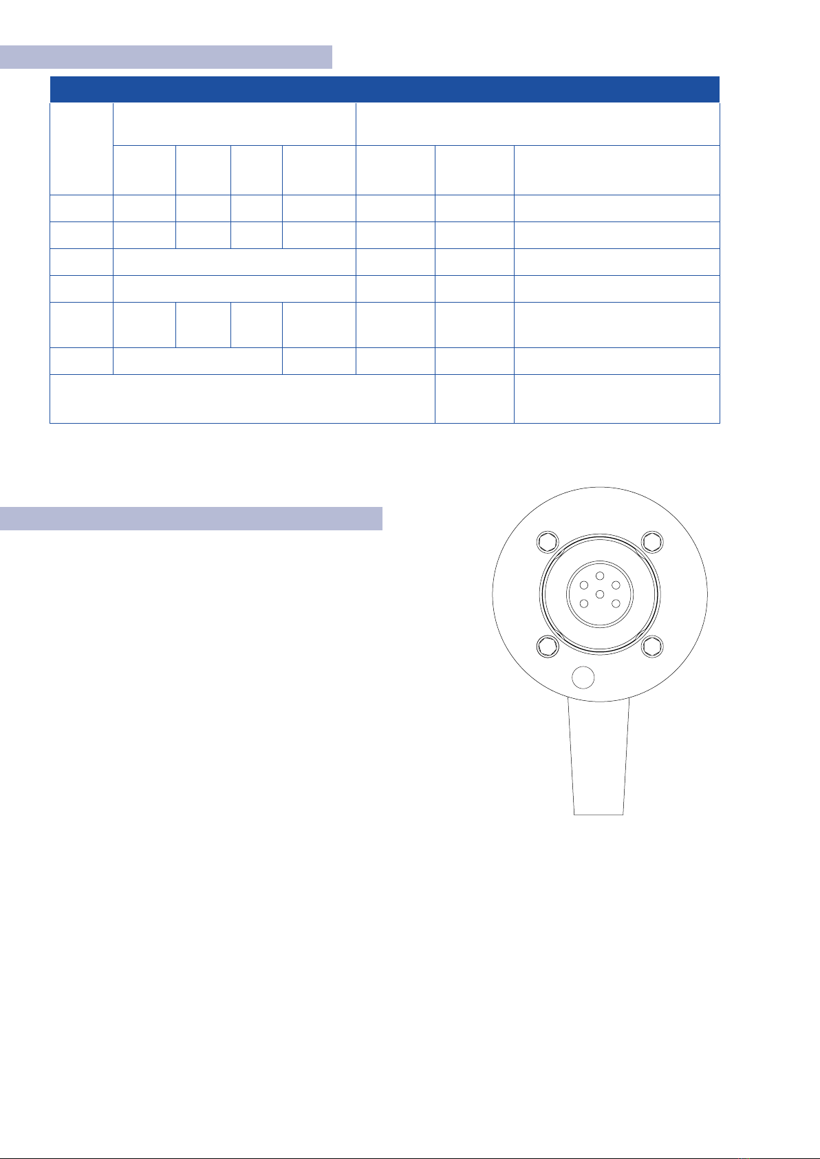
2.8 Wiring Pin-outs
V7 Cable Pin-Out
Contact
Pin-Out Cable
ARCNET RS232 RS485 V7 Conn.
Ethernet
Conductor
Colour V6
Conductor
Colour V7 Conductor ID
1 A TX A TX_P Yellow Blue UTP #1: 0.22mm² / ~24 AWG
2 B RX B TX_N Blue White UTP #1: 0.22mm² / ~24 AWG
3 +VDC Red Red 0.5mm² / ~20 AWG
4 -VDC Black Black 0.5mm² / ~20 AWG
5 N/C RS232
GND N/C RX_P Green Red UTP #1: 0.22mm² / ~24 AWG
6 Earth RX_N Screen White UTP #1: 0.22mm² / ~24 AWG
Chassis Earth Connection Screen /
Drain Wire
Foil Screen with
Drain wire 0.022mm²
Cable Connector
Pin View
1
435
Screen
62
2.9 Tritech V7 Connector
TheV7 cable connector has the addition of the screen pin in the outer
ring of the connector. This makes contact with the chassis ground of
the system which is required when using Ethernet Comms.
When using ARCNET and Serial Communications systems, standard
cables are compatible.
9
0688-SOM-00001, Rev: 02 © Tritech International Ltd.
4. SeaNet Pro
SeaNet Pro is Tritech’s proprietary software which enables control and communication to our full range of
products. SeaNet Pro is capable of displaying and outputting multiple sensors simultaneously. This means Sonar,
Bathy and PA Altimeter data can all be displayed on the same screen.
4.1 Software Overview
SeaNet Pro is Tritech’s survey data acquisition and logging software package. Seanet Pro can simultaneously run
and display several combinations of Imaging Sonar, Profiling Sonar, USBL Positioning, Bathymetric and Sidescan
sensors. Seanet Setup is used to display status of all connected nodes and to download new software and
firmware upgrades into the subsea devices.
4.2 System Requirements
In order to install and run SeaNet Pro to its full potential, the operating system should meet the
following system requirements:
Minimum Recommended
Processor 2GHz 2GHz dual core
RAM 1GB 2GB
Graphics 3D hardware accelerated graphics card
OpenGL Version 2.0 or greater
Display 1280x1024 (32bit colour) 1600x1200 (32bit colour)
Disk space
Serial Hardware based, or USB converters for RS232 or RS485 communications
Networking 100MB/s (fast Ethernet) 1000MB/s (Gigabit Ethernet)
4.3 SeaNet Pro Software Installation.
Tritech Software is provided with each purchase of our equipment
either on CD-ROM or a USB memory stick.
Updates and latest versions of software can also be downloaded from
the Tritech website www.moog.com/tritech
Once installed, you can launch the application from the desktop icon
or from the Start menu in windows.
Updates
Download the latest software versions from www.moog.com/tritech
Tritech International Ltd continually develop our software so it is recommended
to check the website for updates regularly.

10
0688-SOM-00001, Rev: 02 © Tritech International Ltd.
4.4 Windows Setup
Ethernet Protocol Settings
The Ethernet adapter needs to be setup on the host PC to be in the same IP address range as the sensor being
attached. Using network comms allows multiple sensors to be integrated using standard networking equipment.
A minimum 100BASE−TX link is recommended. The Ethernet enabled Tritech Systems Require 100Mbps in order
to function correctly and may not work on lower 10BASE−T lines. It’s not recommended to connect Tritech units
through a network hub, a network switch is recommended to be used instead.
Note
If Ethernet devices don’t appear when connected and powered on, check
the computer’s TCP/IPv4 settings in Windows Network Centre and ensure the
IP address and Subnet masks use the correct range of 192.168.2.XXX with
Subnet Mask 255.255.255.0
Do not set the host computer IP address the any of the sonar devices or reserved
addresses xxx.2.17, xxx.2.200, xxx.2.201
Also, do not use the“Obtain an IP address automatically”option.
Warning
By default our Ethernet enabled systems have their subnet set to ‘2’. and main IP
address set to 192.168.2.17. Make sure that the host computer’s IP address does
not conflict with this IP address.
Windows Firewall Settings
Check your anti-virus settings. Firewalls will see the data
from the network and may stop the broadcast message.
Occasionally a firewall will allow the broadcast message
but will stop the high data rate from the sensor believing it
to be a denial of service attack. If this is the case, navigate
to “Allowed Apps” in windows and add permissions to the
firewall settings for Seanet Software.
Serial Comms Setup
COM port allocations vary depending on the computer
you use. They can be found by opening Windows Device
Manager where there is a list of COM ports called Ports
(COM & LPT).
NOTE
When using ARCNET It is worth noting that a SeaHub or Tritech SCU is required
to interface with the sensor. This is because Tritech use our own proprietary
version of the ARCNET protocol.
Wiring diagrams and pin-outs can be found in section 2.6 of this manual..
11
0688-SOM-00001, Rev: 02 © Tritech International Ltd.
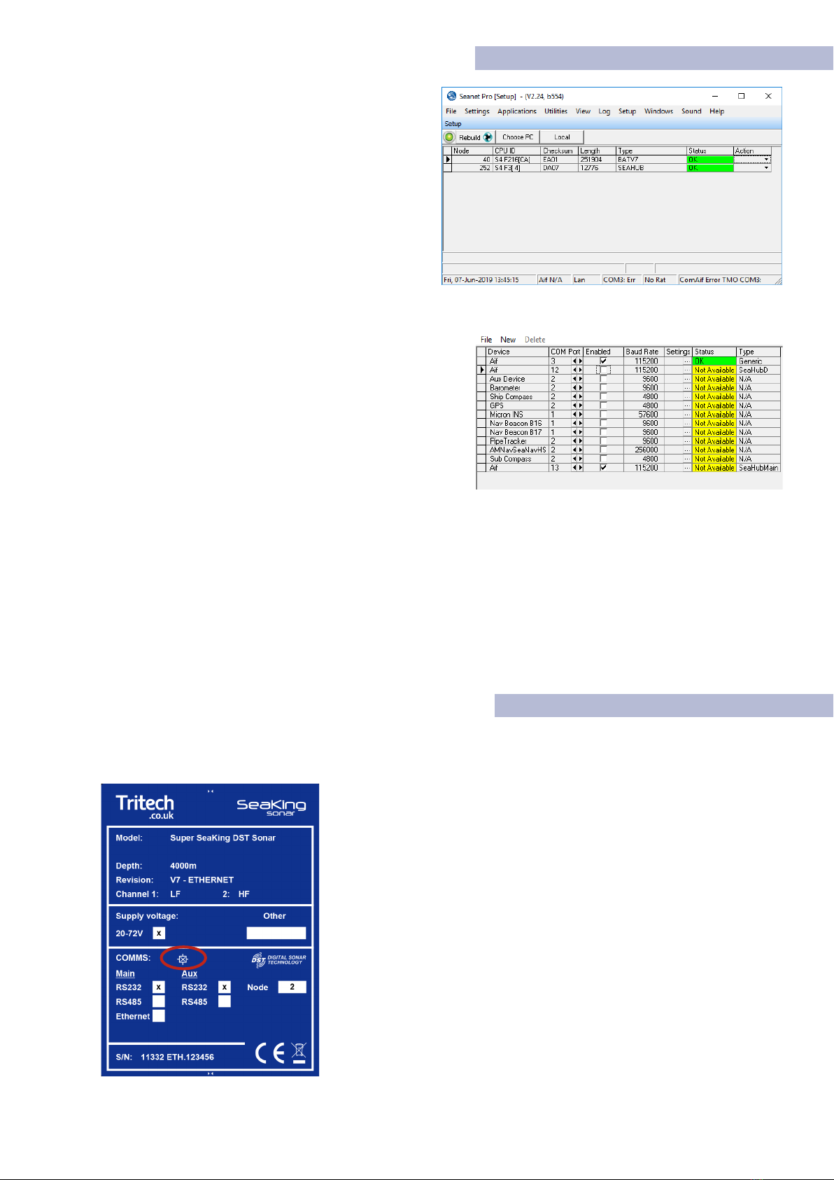
4.5 SeaNet Pro Setup
Setup window
Having installed the hardware it is now time to setup
communications within SeaNet Pro.
To do this go to the Applications in menu at the top of
the screen and select Setup.
This brings up the Node list where the sensors will
appear.
If using Ethernet the sensor will be detected
automatically and will appear in the Node list.
Serial Comms Setup
Make sure the com ports are activated by clicking the
Utilities menu and select Com Setup.
In the Channel Setup dialogue (right) that appears, find the
entry called“Aif”(by default, it is the top entry). if not, it can
be added by selecting New then Aif.
Check the com port number is correct and corresponds to
the port of your device and that the Enabled check box is
ticked.
When SeaNet Pro’s comms Interface has been properly configured, the device/s will appear in the Node List
where they can be fully configured.
Changing the Comms Protocol of the Device
The comms protocol on V7 systems is software selectable. This means changing between Ethernet/Arcnet and
serial comms can be done from the node list in Seanet Pro setup. Click on the drop-down under the Actions
column in the node list to bring up the Device Setup Window. Full details can be found in section 4.
4.6 Magnetic Reset
If the comms mode or baud rate of a system has been changed to an unknown state, there is a quick solution to
reset the communications protocol to a known state.
The following steps will reset the unit to RS232 comms protocol..
◊ Connect the unit under test to an available RS-232 interface.
◊ Do not apply power just yet.
◊ Return to ‘Seanet Setup’.
◊ Ensure the Com Port of the device is setup and enabled
◊ Place a S11247 magnet on the Reset symbol on the label (Circled in red).
◊ Hold the magnet in position and power up the instrument.
◊ When the node appears in Seanet Setup, remove the magnet.
If after 15 seconds, the device does not appear in the Seanet Node list,
ensure magnet is aligned correctly and cycle the power.
12
0688-SOM-00001, Rev: 02 © Tritech International Ltd.
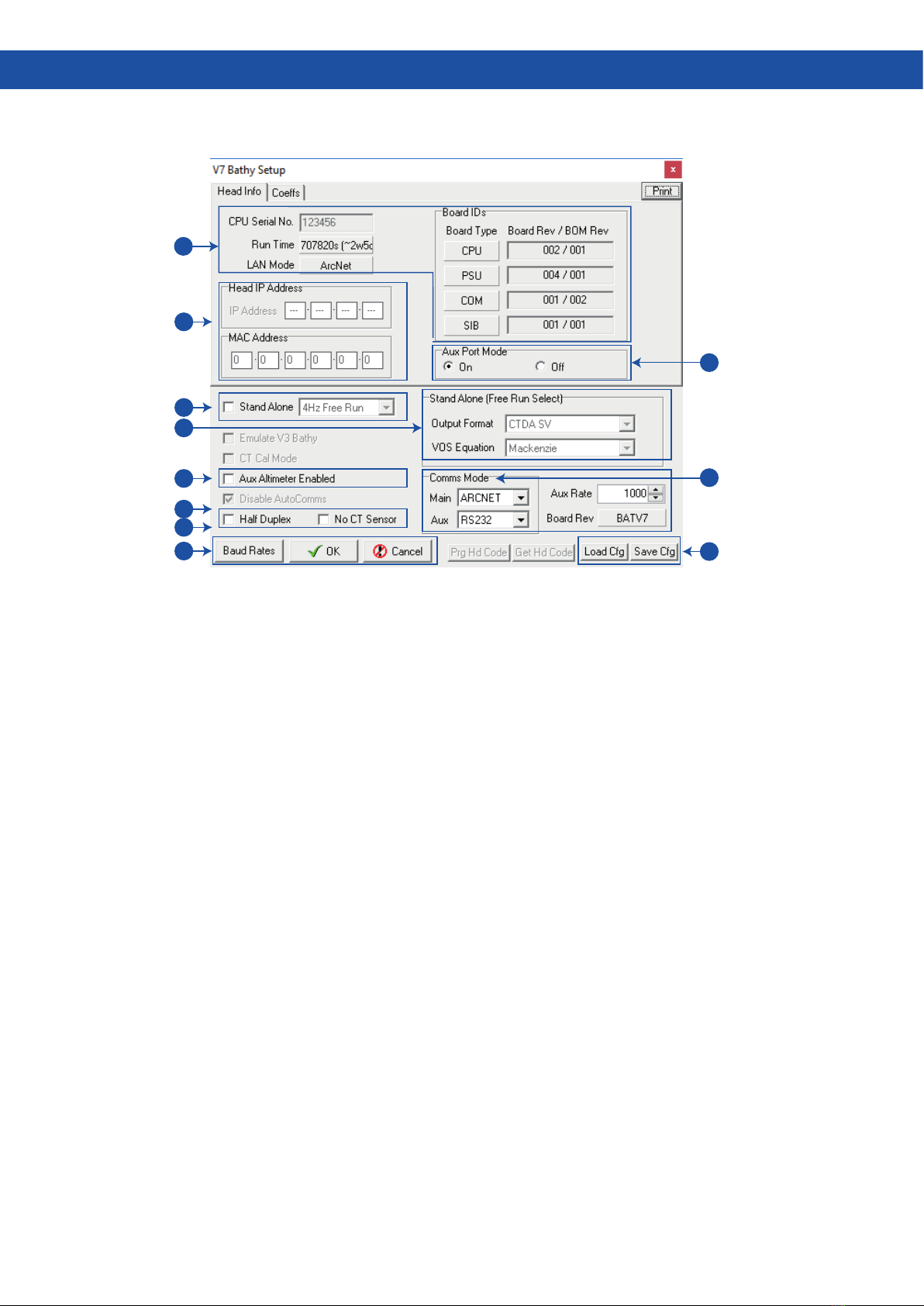
1. Head Info/Coes Tab- Information relating to
the instrument build. The Run Time field will
show the total time the instrument has been logging
for (between calibration dates). LAN Mode will either
be ARCNET or ETHERNET dependant on system
configuration.
2. Head IP Address- This section is only relevant to
‘ETH’ instrument variants. The IP Address field is
modifiable to allow reprogramming of the static IP set
by the factory. The MAC Address is a read only control
that displays the allocated MAC for the instrument,
and will be populated at the factory during build.
3. Standalone Mode- This enables the alternate
‘stand-alone’ communications mode. In this
mode, the instrument will output ASCII text in a
range of CSV formats. Output rates range from 1-4Hz
(free-running), as well as the option to interrogate for
data. For further details about ‘stand-alone’ mode, see
Appendix C.
4. Output Format- These settings are in respect
to ‘stand-alone’ operational mode. The output
format drop-down offers a range of string formats.
For output formats including ‘SV’(Sound Velocity), the
VOS equation drop-down offers a range of industry
standard VOS calculations. Please note these VOS
calculations are only in respect to ‘stand-alone’ mode,
and will not affect the value derived in Seanet (when
running in normal operational mode).
5. Aux Altimeter Enabled- This setting notifies the
instrument to reserve the AUX port for a Tritech
PA (altimeter). By default, this option will be checked.
6. Half Duplex- This option is auto-selected when
operating over RS-485. It may also be required
when operating over RS-232 via a serial MUX.
7. No CT Sensor- This is a factory-only option, and
is specific to the SK701 instruments.
8. Baud Rates- This control will open the Baud Rate
setup dialog.This window allows the operator to
make changes to the Main/Aux port communications
speeds. For further details on changing comms modes,
please see section 3.4.
9. Aux Port Mode- This control allows the
operator to turn off power to the AUX port on
the instrument. Please note that even if the AUX Port
Mode is set to off, a blanking cap must still be fitted
to the AUX port before immersion of the instrument.
10.
COMMS Mode- These controls allow changing
of the communication modes for both
MAIN and AUX. For further details on changing the
communication modes, see section 3.4
11.
Load/Save Cfg- This allows the operator to
save the current settings/coefficients to a
‘UserBBCfg’ file. It also offers the option of loading a
previous ‘UserBBCfg’ file back into the instrument.
These can be provided by the factory if accidental
changes are made to the instrument settings.
4. Device Configuration Window
The device Configuration window is accessed from the node list by clicking on the drop-down (under the action
column) and selecting setup. Below is an overview of the Configuration window.
1
11
9
10
3
4
2
5
6
7
8
13
0688-SOM-00001, Rev: 02 © Tritech International Ltd.
4.1 Seanet Pro Operation
The Following section covers basic operation within SeaNet Pro.The SeaKing 700 series can be operated alongside
other devices in a multi-window application. For this example we will focus on the Single Bathy Application.
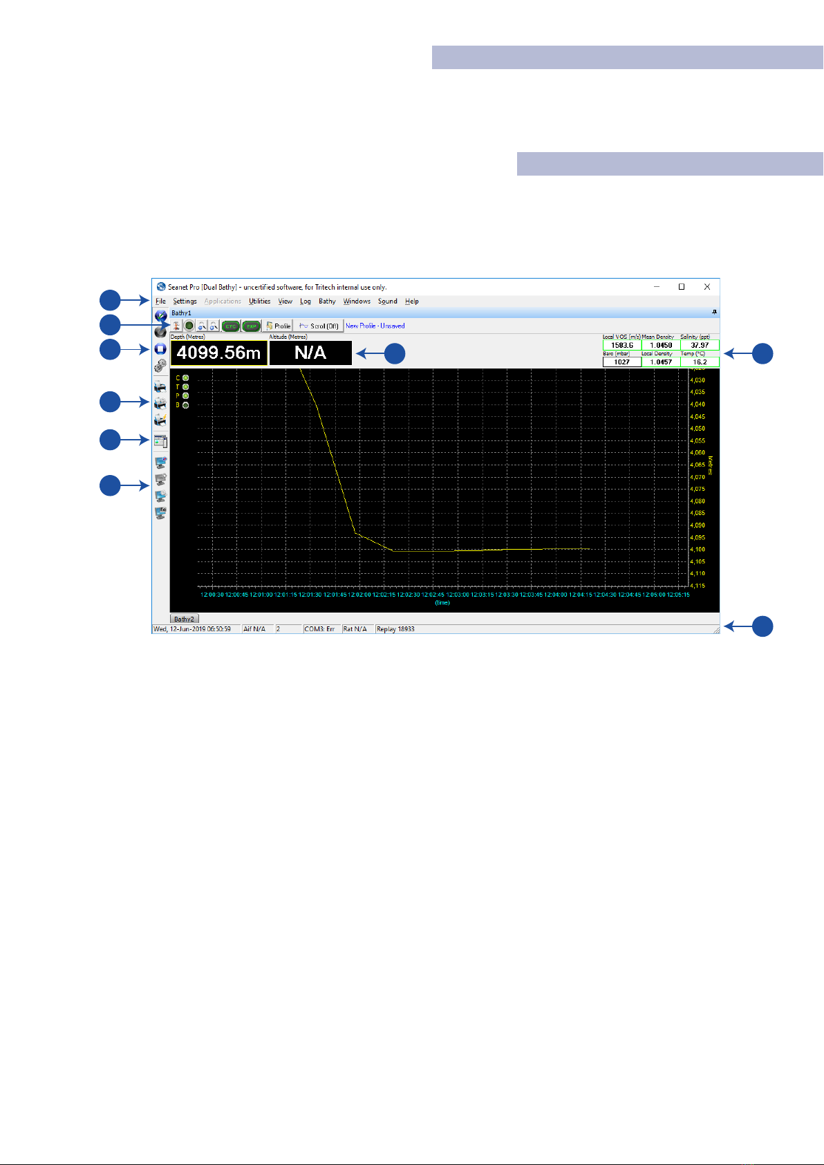
4.2 Main Screen
In the Applications menu at the top of the window, select “Single Bathy” to bring up the main Bathy interface
screen. Below is brief overview of the Bathy Application window.
1
8
9
7
3
2
4
5
6
1. Main Seanet Menu- This accesses the global
functions of Seanet Pro. Here you will also find
environmental offsets and configuration for devices as
well as the ability to load and playback stored log files.
2. Bathymetric Settings Bar- Quick access to some
of the basic functions of the bathy. To the left is
the Application tools button which accesses the bathy
setup and configuration. See section 3.9 for full details
on the Application Tools Menu. Next is the start/stop
sensor button.
3. Logging Short- Cuts- Logging controls to load
existing log files, Start and stop a new log. The
gears icon accesses the log settings panel to select file
destinations
4. Print Bar- Print, Quick Print and Print setup
options for printing the screen data.
5. Side Bar Short-cut- Opens a side bar which can
be used as an events logger or to store project
specific information to the log.
6. Screen Capture- Seanet Pro has it’s own screen
capture built in. Basic start/stop and setup can
be found here.
7. Depth and Altitude - Text boxes that display
live depth and altitude reading . Note that“NA”is
displayed when no Altimeter is connected.
8. Bathymetric Data- The system displays sensor
measurements for VoS, Density, Salinity, pressure
and temperature.
9. System information bar- Seanet system
information including local time and com status
are displayed.
The Bathy Application generates a rolling display showing depth against time. The two main toolbars used
consist of the data display bar (running horizontally across the top of the bathy application), and the Seanet
controls short-cut bar (running vertically down the LHS of the display). There are two main toolbars, one long
the top of the screen and one vertically on the left of the depth profile.
14
0688-SOM-00001, Rev: 02 © Tritech International Ltd.
4.3 SeaNet Pro Tools
Bathy Application Menu
The Bathy application menu can be accessed either by clicking the
menu icon in the top left of the top toolbar or by right clicking the
mouse in the Bathy application window.
Here you can access all settings and information screens for the bathy.
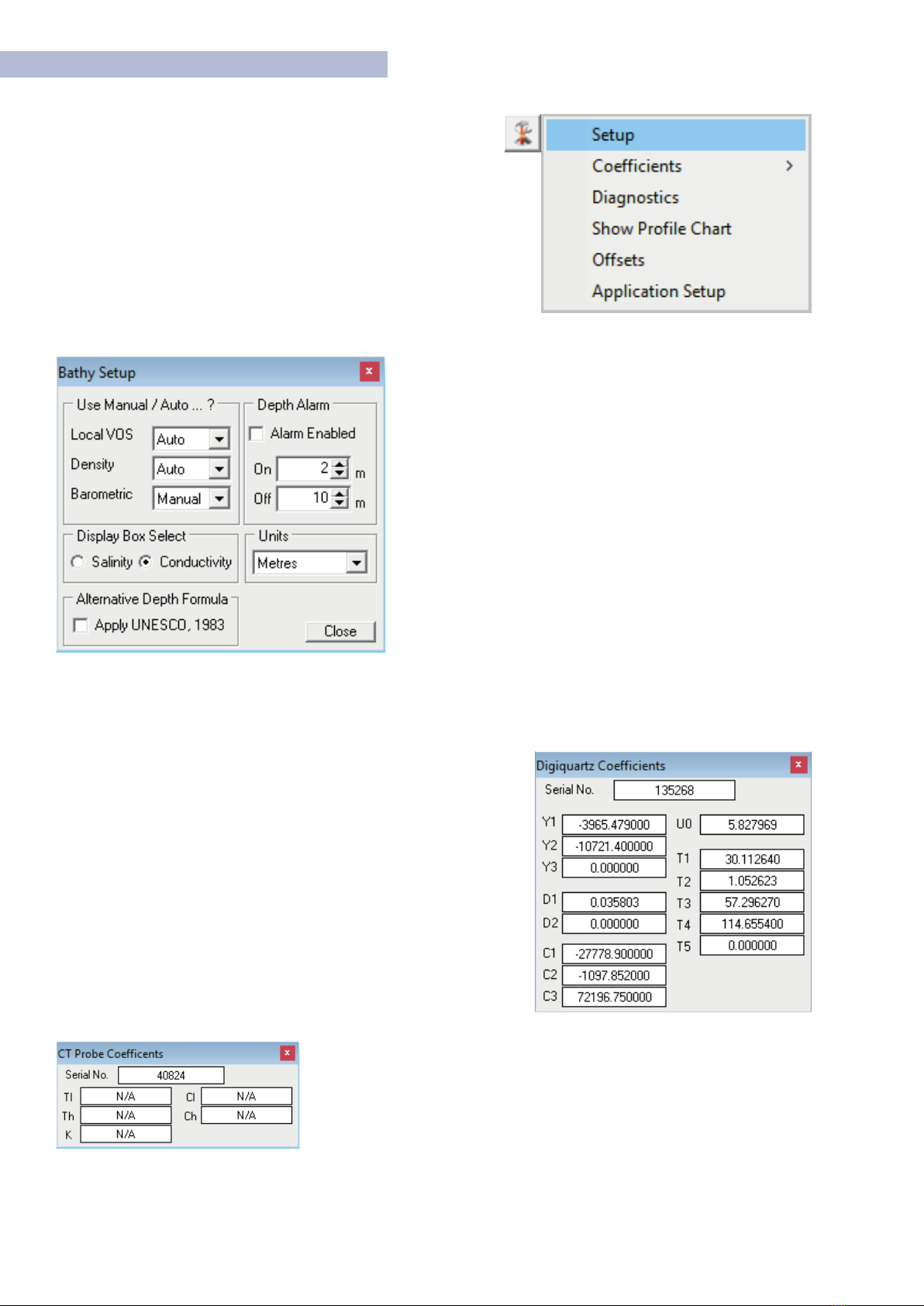
Setup
Set Auto or Manual values for Local VOS, Density, and
Barometric. If Auto, the application calculates the correct
based on Bathymetric data available. Otherwise manually
entered values must be applied in the environmental settings.
Display Box Select - Toggles the display between Salinity or
Conductivity in the top right of the main Bathy Screen.
Alternative Depth Formula - Uses the UNESCO standard
depth calculation described in Appendix B .
Depth Alarm - Set the depth range for alert. When activated,
the Bathymetric Display will flash.
Units - Selects units of measurement Meters, Feet, Fathom
or Yards.
Coecients / View DQ Coecients
Opens a pop-up window displaying all coefficient data relating to the
Digiquarts. These values are calculated during the calibration process
of the Bathy.
This data is for information only and cannot be modified. If Coefficient
values need to be updated please refer to the CoeffsTab in the Device
Configuration window as outlined in section 3.6
Coecients / View CT Coecients
This is a legacy option from the V3 Bathy and is not relevant to V7 systems.
Only the CT probe serial number is available to view.
This manual suits for next models
2
Table of contents


