Moog PFH10 SERIES User manual
Moog Inc.
Sensor and Surveillance Systems
3650 Woodhead Drive Northbrook, IL. USA 60062
+1.847.498.0700 Fax: +1.847.498.1258 www.moogS3.com
PFH10
Fusion Pressurized and Dust-Proof Tubular Environmental Camera Housings
PFH10C2W................ A Pressurized tubular housing, 24Vac or 12Vdc input, heater & blower with feed-thru wall / pole mount
PFH10C2WY.............. Pressurized tubular housing, 24Vac or 12Vdc input, heater & blower with feed-thru wall / pole mount, adjustable sunshield
PFH10C8WY.............. Pressurized tubular housing, PoE input with Dynamic Power Allocation, 30 watt midspan included, heater & blower with feed-thru wall /
pole mount, supports .af PoE cameras, adjustable sunshield
DFH10C2W................Dust-Proof tubular housing, 24Vac or 12Vdc input, heater & blower with feed-thru wall / pole mount
DFH10C2WY.............. Dust-Proof tubular housing, 24Vac or 12Vdc input, heater & blower with feed-thru wall / pole mount, adjustable sunshield
DFH10C8WY.............. Dust-Proof tubular housing, PoE input with Dynamic Power Allocation, 30 watt midspan included, heater & blower with feed-thru wall /
pole mount, supports .af PoE cameras, adjustable sunshield
Installation and Operation Instructions
Before attempting to connect or operate this product, please
read these instructions completely.
© 2013, Moog Inc. All Rights Reserved 81-IN5480 110513

IMPORTANT SAFEGUARDS SAFETY PRECAUTIONS
UNPACKING
SERVICE
1 Read these instructions.
2 Keep these instructions.
3 Heed all warnings
4 Follow all instructions.
5 Do not use this apparatus near water.
6 Clean only with damp cloth.
7 Do not block any of the ventilation openings. Install in accordance with the
manufacturers instructions.
8 Cable Runs- All cable runs must be within permissible distance.
9 Mounting - This unit must be properly and securely mounted to a supporting
structure capable of sustaining the weight of the unit.
Accordingly:
a. The installation should be made by a qualied installer.
b. The installation should be in compliance with local codes.
c. Care should be exercised to select suitable hardware to install the unit, taking into
account both the composition of the mounting surface and the weight of the unit.
10 Do not install near any heat sources such as radiators, heat registers, stoves, or other
apparatus ( including ampliers) that produce heat.
11 Do not defeat the safety purpose of the polarized or grounding-type plug. A
polarized plug has two blades with one wider than the other. A grounding type
plug has two blades and a third grounding prong. The wide blade or the third
prong are provided for your safety. When the provided plug does not t into your
outlet, consult an electrician for replacement of the obsolete outlet.
12 Protect the power cord from being walked on or pinched particularly at plugs,
convenience receptacles, and the point where they exit from the apparatus.
13 Only use attachment/ accessories specied by the manufacturer.
14 Use only with a cart, stand, tripod, bracket, or table specied by the manufacturer,
or sold with the apparatus. When a cart is used, use caution when moving the cart/
apparatus combination to avoid injury from tip-over.
15 Unplug this apparatus during lighting storms or when unused for long periods of time.
16 Refer all servicing to qualied service personnel. Servicing is required when the
apparatus has been damaged in any way, such as power-supply cord or plug is
damaged, liquid has been spilled of objects have fallen into the apparatus, the
apparatus has been exposed to rain or moisture, does not operate normally, or
has been dropped.
Be sure to periodically examine the unit and the supporting structure to make sure that the integrity
of the installation is intact. Failure to comply with the foregoing could result in the unit separating
from the support structure and falling, with resultant damages or injury to anyone or anything struck
by the falling unit.
Unpack carefully. Electronic components can be
damaged if improperly handled or dropped. If an item
appears to have been damaged in shipment, replace
it properly in its carton and notify the shipper.
Be sure to save:
1 The shipping carton and packaging material.
They are the safest material in which to make future
shipments of the equipment.
2 These Installation and Operating Instructions.
If technical support or service is needed, contact us at
the following number:
The lightning ash with an arrowhead symbol,
within an equilateral triangle, is intended to
alert the user to the presence of non-insulated
“dangerous voltage” within the product’s
enclosure that may be of sufcient magnitude
to constitute a risk to persons.
Este símbolo se piensa para alertar al usuario a la presencia
del “voltaje peligroso no-aisIado” dentro del recinto de los
productos que puede ser un riesgo de choque eléctrico.
Ce symbole est prévu pour alerter I’utilisateur à la presence
“de la tension dangereuse” non-isolée dans la clôture de
produits qui peut être un risque de choc électrique.
Dieses Symbol soll den Benutzer zum Vorhandensein der
nicht-lsolier “Gefährdungsspannung” innerhalb der
Produkteinschließung alarmieren die eine Gefahr des
elektrischen Schlages sein kann.
Este símbolo é pretendido alertar o usuário à presença “di
tensão perigosa non-isolada” dentro do cerco dos produtos
que pode ser um risco de choque elétrico.
Questo simbolo è inteso per avvertire I’utente alla presenza
“di tensione pericolosa” non-isolata all’interno della
recinzione dei prodotti che può essere un rischio di scossa
elettrica
.
The exclamation point within an equilateral
triangle is intended to alert the user to
presence of important operating and
maintenance (servicing) instructions in the
literature accompanying the appliance.
Este símbolo del punto del exclamation se piensa para
alertar al usuario a la presencia de instrucciones importantes
en la literatura que acompaña la aplicación.
Ce symbole de point d’exclamation est prévu pour alerter
l’utilisateur à la presence des instructions importantes dans
la littérature accompagnant l’appareil.
Dieses Ausruf Punktsymbol soll den Benutzer zum
Vorhandensein de wichtigen Anweisungen in der Literatur
alarmieren, die das Gerät begleitet.
Este símbolo do ponto do exclamation é pretendido alertar o
usuário à presença de instruções importantes na literatura
que acompanha o dispositivo.
Questo simbolo del punto del exclamaton è inteso per
avvertire l’utente alla presenza delle istruzioni importanti nella
letteratura che accompagna l'apparecchio.
TECHNICAL SUPPORT
AVAILABLE 24 HOURS
1- 800-554 -1124
RISK OF ELECTRIC SHOCK
DO NOT OPEN
CAUTION
CAUTION: TO REDUCE THE RISK OF
ELECTRIC SHOCK, DO NOT REMOVE
COVER ( OR BACK). NO USER- SERVICE-
ABLE PARTS INSIDE. REFER SEVICING
TO QUALIFIED SERVICE PERSONNEL.
MADEIN
BUY AMERICA COMPLIANT • COUNTRY OF ORIGIN U.S.A.
USA

Product Warranty Registration
Register Your Products Online
www.moogS3.com/technical-support/product-registration
Moog values your patronage. We are solely committed to providing you with the highest quality products and
superior customer service. With 3-Year and 5-Year warranties (depending on the product purchased) we stand
behind every product we sell.
:
• Simple and Trouble-Free RMA process
• Product / software updates
• Special promotions
• Eliminate the need to archive purchase documents such as receipts, purchase orders,etc.
See full warranty details at www.moogS3.com/technical-support/warranty-plan/

Limited Warranty for Moog Products
Moog - Decatur Operations, subsequently referred to as “Manufacturer,” warrants these products to be free from defects in material or workmanship as follows:
During the labor warranty period, to repair the Product, Purchaser will either return the defective product, freight prepaid, or deliver it to Manufacturer at Moog Decatur
Operations, 2525 Park Central Boulevard, Decatur, Georgia, 30035. The Product to be repaired is to be returned in either its original carton or a similar package affording
an equal degree of protection with a RMA # (Return Materials Authorization number) displayed on the outer box or packing slip. To obtain a RMA# you must contact our
Technical Support Team at 800.554.1124, extension 101. Manufacturer will return the repaired product freight prepaid to Purchaser. Manufacturer is not obligated to
provide Purchaser with a substitute unit during the warranty period or at any time. After the applicable warranty period, Purchaser must pay all labor and/or parts charges.
The limited warranty stated in these product instructions is subject to all of the following terms and conditions.
TERMS AND CONDITIONS
1. NOTIFICATION OF CLAIMS: WARRANTY SERVICE: If Purchaser believes that the Product is defective in material or workmanship, then written notice with an explanation
of the claim shall be given promptly by Purchaser to Manufacturer. All claims for warranty service must be made within the warranty period. If after investigation,
Manufacturer determines the reported problem was not covered by the warranty, Purchaser shall pay Manufacturer for the cost of investigating the problem at its then
prevailing per incident billable rate. No repair or replacement of any Product or part thereof shall extend the warranty period of the entire Product. The specic warranty on
the repaired part only shall be in effect for a period of ninety (90) days following the repair or replacement of that part or the remaining period of the Product parts warranty,
whichever is greater.
2. EXCLUSIVE REMEDY: ACCEPTANCE: Purchaser’s exclusive remedy and Manufacturer’s sole obligation is to supply (or pay for) all labor necessary to repair any Product
found to be defective within the warranty period and to supply, at no extra charge, new or rebuilt replacements for defective parts.
3. EXCEPTIONS TO LIMITED WARRANTY: Manufacturer shall have no liability or obligation to Purchaser with respect to any Product requiring service during the warranty
period which is subjected to any of the following: abuse, improper use, negligence, accident, or acts of God (i.e., hurricanes, earthquakes), modication, failure of the
end-user to follow the directions outlined in the product instructions, failure of the end-user to follow the maintenance procedures recommended by the International Security
Industry Organization, written in product instructions, or recommended in the service manual for the Product. Furthermore, Manufacturer shall have no liability where a
schedule is specied for regular replacement or maintenance or cleaning of certain parts (based on usage) and the end-user has failed to follow such schedule; attempted
repair by non-qualied personnel; operation of the Product outside of the published environmental and electrical parameters, or if such Product’s original identication
(trademark, serial number) markings have been defaced, altered, or removed. Manufacturer excludes from warranty coverage Products sold AS IS and/or WITH ALL FAULTS
and excludes used Products which have not been sold by Manufacturer to the Purchaser. All software and accompanying documentation furnished with, or as part of the
Product is furnished “AS IS” (i.e., without any warranty of any kind), except where expressly provided otherwise in any documentation or license agreement furnished with
the Product. ANY COST ASSOCIATED WITH REMOVAL OF DEFECTIVE PRODUCT AND INSTALLATION OF REPLACEMENT PRODUCT IS NOT INCLUDED IN THIS WARRANTY.
4. PROOF OF PURCHASE: The Purchaser’s dated bill of sale must be retained as evidence of the date of purchase and to establish warranty eligibility.
PRODUCT CATEGORY PARTS \ LABOR
All Enclosures and Electronics Five (5) Years
Accessory Brackets Five (5) Years
Controllers Three (3) Years
Power Supplies / IR Illuminators Three (3) Years
Poles / PolEvators™ / CamEvator Three (3) Years
Warrior Series™ / Q-View™Three (3) Years
SView Series™Three (3) Years 6 months if used in auto scan / tour operation
DeputyDome™, NiteTrac™, Igloo Dome, PurgeDome™Three (3) Years 6 months if used in auto scan / tour operation
EXO Series™Dome and Fixed Camera Systems* Three (3) Years 6 months if used in auto scan / tour operation
EXO Series™GeminEye Visible and Thermal Camera Systems One (1) Year
DISCLAIMER OF WARRANTY
EXCEPT FOR THE FOREGOING WARRANTIES, MANUFACTURER HEREBY DISCLAIMS AND EXCLUDES ALL OTHER WARRANTIES, EXPRESS OR IMPLIED, INCLUDING, BUT
NOT LIMITED TO ANY AND/OR ALL IMPLIED WARRANTIES OF MERCHANTABILITY, FITNESS FOR A PARTICULAR PURPOSE AND/OR ANY WARRANTY WITH REGARD TO ANY
CLAIM OF INFRINGEMENT THAT MAY BE PROVIDED IN SECTION 2-312(3) OF THE UNIFORM COMMERCIAL CODE AND/OR IN ANY OTHER COMPARABLE STATE STATUTE.
MANUFACTURER HEREBY DISCLAIMS ANY REPRESENTATIONS OR WARRANTY THAT THE PRODUCT IS COMPATIBLE WITH ANY COMBINATION OF NON-MANUFACTURER
PRODUCTS OR NON-MANUFACTURER RECOMMENDED PRODUCTS PURCHASER MAY CHOOSE TO CONNECT TO THE PRODUCT.
LIMITATION OF LIABILITY
THE LIABILITY OF Manufacturer, IF ANY, AND PURCHASER’S SOLE AND EXCLUSIVE REMEDY FOR DAMAGES FOR ANY CLAIM OF ANY KIND WHATSOEVER, REGARDLESS
OF THE LEGAL THEORY AND WHETHER ARISING IN TORT OR CONTRACT, SHALL NOT BE GREATER THAN THE ACTUAL PURCHASE PRICE OF THE PRODUCT WITH RESPECT
TO WHICH SUCH CLAIM IS MADE. IN NO EVENT SHALL MANUFACTURER BE LIABLE TO PURCHASER FOR ANY SPECIAL, INDIRECT, INCIDENTAL, OR CONSEQUENTIAL
DAMAGES OF ANY KIND INCLUDING, BUT NOT LIMITED TO, COMPENSATION, REPLACEMENT LABOR COSTS, REIMBURSEMENT, OR DAMAGES ON ACCOUNT OF THE LOSS
OF PRESENT OR PROSPECTIVE PROFITS OR FOR ANY OTHER REASON WHATSOEVER.
* NOTE
Moog will repair or replace, at its option, any equipment which is damaged by transient voltage surge/spike or lightning strike (an “Occurrence”), while properly connected
to wired AC power line with protective ground. Any repair or modication of the equipment done by someone other than Moog voids the warranty.
Form 500-911 081913
PFH10
Value Features
Hand Hold
underlaid grip point
Multi-Plane
Adjustable SunShield
position to protect
against glare on lens
Cable Feed Through
hides and protects cables
Pop Out Tabs
allows for
pole mounting
Rear Access Panel
acts as internal J-Box
Installers Connection Board
allows for easy hook-ups
Lanyard Cable
safely retains housing
during installation
Durable and Attractive
“grite” color powder coated
nish. (increased corrosion
protection nish available)
Optional Accessory

Contents of Box
Midspan
for
Some Models
Hardware Packet
PFH10
24Vac 29W (No camera)
12Vdc 11W (No camera)
PoE: OUT IEEE802.af
24Vac 29W (Ninguna cámara)
12Vdc 11W (Ninguna cámara)
PoE: OUT IEEE802.af
24Vac 29W (Aucun appareil-photo)
12Vdc 11W (Aucun appareil-photo)
PoE: OUT IEEE802.af
24Vac 29W (Keine Kamera)
12Vdc 11W (Keine Kamera)
PoE: OUT IEEE802.af
24Vac 29W (Nenhuma câmera)
12Vdc 11W (Nenhuma câmera)
PoE: OUT IEEE802.af
24Vac 29W (Nessuna macchina fotografica)
12Vdc 11W (Nessuna macchina fotografica)
PoE: OUT IEEE802.af
Electrical Specifications
Power 12VDC
Class 2 Only
!!
Français
Deutsch
Italiano
Portuguese
Español
English
ADDITIONAL DETAIL TO BE UPDATED IN FUTURE REVISIONS

CAUTION: When assembling the mounting bracket, make sure
all the wiring access holes are facing towards the rear of the
base mounts access portal.
• PRECAUCIÓN: Al montar la consola de montaje, cerciórese de que todos los agujeros
de acceso del cableado son revestimiento hacia la parte posterior del portal bajo del
acceso de los montajes.
• ATTENTION : En assemblant le support, assurez-vous que toutes les ouvertures
d'accès de câblage sont revêtement vers l'arrière du portail bas d'accès de bâtis.
• VORSICHT: Wenn Sie die Schienenplatte zusammenbauen, stellen Sie sicher, dass alle
VerdrahtungsZugangslöcher Einfassung in Richtung zur Rückseite des niedrigen
Einfassungszugangsportals sind.
• CUIDADO: Ao montar o suporte, certique-se que todos os furos de acesso da ação
são revestimento para a parte traseira do portal baixo do acesso das montagens.
• ATTENZIONE: Nel montare il montaggio - la staffa, si assicura che tutti i fori di
accesso dei collegamenti siano rivestimento verso la parte posteriore del portale
basso di accesso dei supporti.
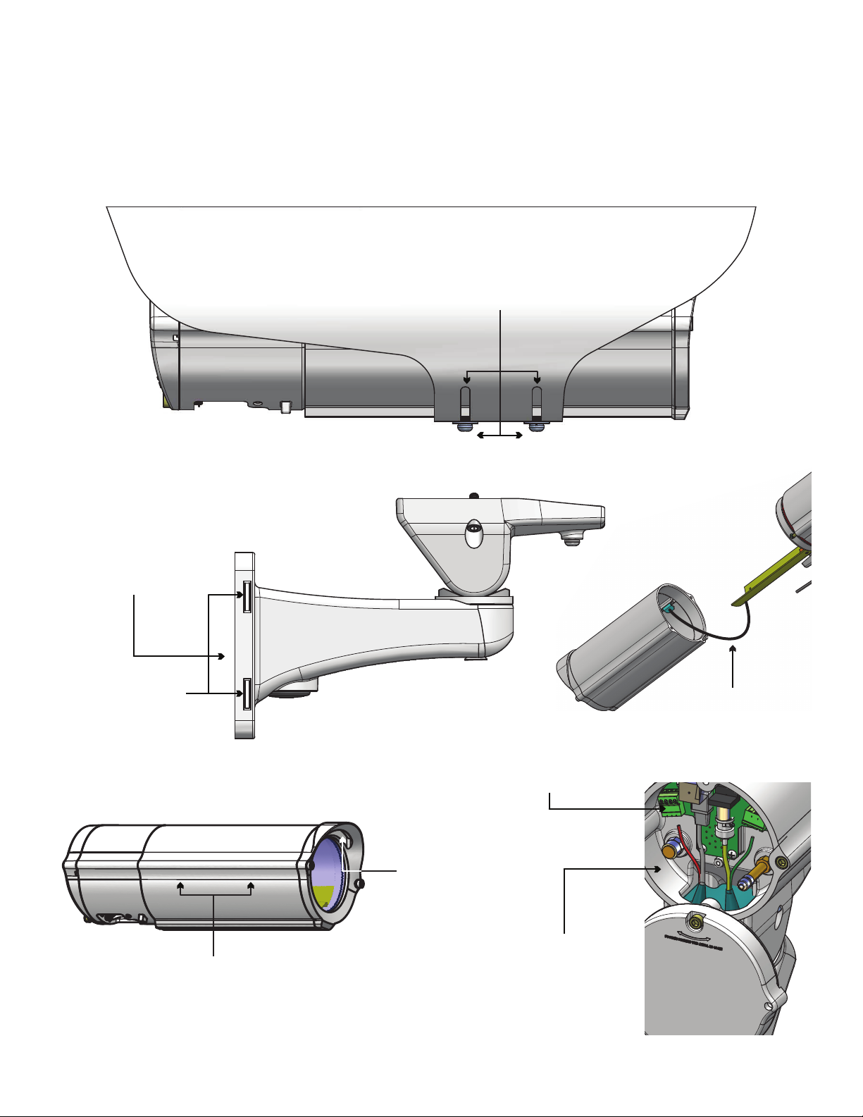
Proper Assembly of Mounting Bracket
Wiring Access Holes:
Must be rear facing
!!
Recommended Hardware for the Mounting Holes:
• 5/16” - 18 (or M8 for metric) x minimum 1 ¼” Hex Head Bolt
• 5/16” Flat Washer
• 5/16” Lock Washer

Mounting Straps Sold Separately
If running wire through a conduit to the housing mount, rst install
appropriate ttings to the mount base.
• Si se ejecuta a través de un cable de conducto a la carcasa de montaje, primero instale los
accesorios adecuados para la base de montaje.
• Si vous utilisez le câble dans un conduit à la monture logement, installez d'abord raccords
appropriés à la base de monture.
• Wenn Laufen Draht über eine Leitung mit dem Gehäuse montieren, installieren Sie zuerst
geeignete Armaturen an der Halterung Basis.
• Se você estiver executando o através de um canal para a montagem de habitação, primeiro
instale acessórios apropriados à base de montagem.
• Se l'esecuzione del lo attraverso un condotto al monte degli alloggi, prima installare raccordi
appropriati per la base di montaggio.
Attach mount to wall with suitable hardware (not provided).
• Ate el montaje a la pared con el hardware conveniente (no proporcionado).
• Attachez le bâti au mur avec le matériel approprié (non fourni).
• Bringen Sie Einfassung zur Wand mit der verwendbaren Hardware an (nicht bereitgestellt).
• Una a montagem à parede com a ferragem apropriada (não fornecida).
• Attacchi il supporto alla parete con ssaggi adatti (non forniti).
WALL MOUNTING
If attaching to pole, rst break away tabs with pliers and remove
(4) strap plugs.
• Si atan al poste, el primeros rompen lejos lengüetas con los alicates y quitan (4) los enchufes
de la correa.
• Si attachant au poteau, les premiers cassent loin des étiquettes avec des pinces et enlèvent
(4) des prises de courroie.
• Bei der Befestigung zum Pfosten, brechen erste weg Vorsprünge mit Zangen und entfernen
(4) Bügelstecker.
• Se unindo ao pólo, o primeiros quebram afastado abas com alicates e removem (4) plugues
da cinta.
• Se attaccando al palo, i primi rompono via le linguette con le pinze e rimuovono (4) la cinghia
tappa.
TAB
POLE MOUNTING
12
3
Thread straps (not provided) through the mount as shown.
• Pase las correas (no incluidos) a través del soporte como se muestra.
• Sangles de la discussion (non fournies) dans le support comme indiqué.
• Themen-Riemen (nicht mitgeliefert) durch die Halterung wie gezeigt.
• Correias do Tópico (não fornecidos) através da montagem imediata.
• Cinghie di discussione (non in dotazione) attraverso il supporto come illustrato.
4

Crimp the connectors as needed. Then use cable ties
on the nipples to secure device, leave extra cable.
• Prense los conectadores según lo necesitado. Entonces utilice las ataduras de cables en las
entrerroscas para asegurar el dispositivo, dejan el cable adicional.
• Sertissez par replis les connecteurs comme nécessaires. Utilisez alors les serres-câble sur les
mamelons pour xer le dispositif, laissent le câble supplémentaire.
• Quetschverbinden Sie die Verbindungsstücke, wie gebraucht. Benutzen Sie dann Kabelbinder
auf den Nippeln, um Vorrichtung zu sichern, lassen Extrakabel.
• Frise os conectores como necessários. Use então cintas plásticas nos bocais para xar o
dispositivo, deixam o cabo extra.
• Unisca i connettori come stati necessari. Allora utilizzi le fascette ferma-cavo sugli ugelli per
assicurare il dispositivo, lasciano il cavo supplementare.
Cable
Crimp
Cable Ties
Feed cable through bracket, pierce the gasket nipples
(as needed). Place the gasket as shown.
• Alimente el cable a través del soporte, perfore las entrerroscas de la junta (según lo necesitado).
Coloque la junta como se muestra.
• Alimentez le câble par la parenthèse, percez les mamelons de garniture (comme nécessaire).
Placez la garniture comme montrée.
• Ziehen Sie Kabel durch Haltewinkel ein, durchbohren Sie die Dichtungsnippel (wie gebraucht).
Setzen Sie die Dichtung wie gezeigt.
• Alimente o cabo através do suporte, perfure os bocais da gaxeta (como necessário). Coloc a
gaxeta como mostrada.
• Alimenti il cavo tramite la staffa, perfori gli ugelli della guarnizione (come stato necessario).
Disponga la guarnizione come indicata.
Cable
Gasket Nipples
56
Feed cable through back of bracket or bottom access point.
Then follow instructions from previous block.
• Alimente el cable a través detrás del soporte o del punto de acceso inferior. Entonces siga las
instrucciones del bloque anterior.
• Alimentez le câble à travers en arrière de la parenthèse ou du point d'accès inférieur. Suivez
alors les instructions du bloc précédent .
• Ziehen Sie Kabel durch zurück des Haltewinkels oder des unteren Zugangspunktes ein.
Befolgen Sie dann Anweisungen vom vorhergehenden Block .
• Seja o cabo completamente do suporte ou do ponto de acesso inferior. Siga então instruções
do bloco precedente.
• Alimenti il cavo attraverso indietro della staffa o del punto di accesso inferiore. Allora segua le
istruzioni dal blocco precedente .
Cable
Entry
Crimp
Cable
Entry
OR
Place the housing on the bracket, use the provided captive
screws and the key to mount.
• Coloque la cubierta en el soporte, utilice los tornillos prisioneros proporcionados y la llave
al montaje.
• Placez le logement sur la parenthèse, employez les vis captives fournies et la clef au bâti.
• Setzen Sie das Gehäuse am Haltewinkel, verwenden Sie die zur Verfügung gestellten
Sicherheitsschrauben und den Schlüssel zur Einfassung.
• Coloc a carcaça no suporte, use os parafusos prisioneiros fornecidos e a chave à montagem.
• Disponga l'alloggiamento sulla staffa, usi le viti prigioniere fornite e la chiave al supporto.
(A-Tighten)
(B- If you plan to separate the front
housing keep this screw loose)
FRONT
HOUSING
78
Pole Mount Option (Use Steel Straps to Mount)
Wall Mount Option
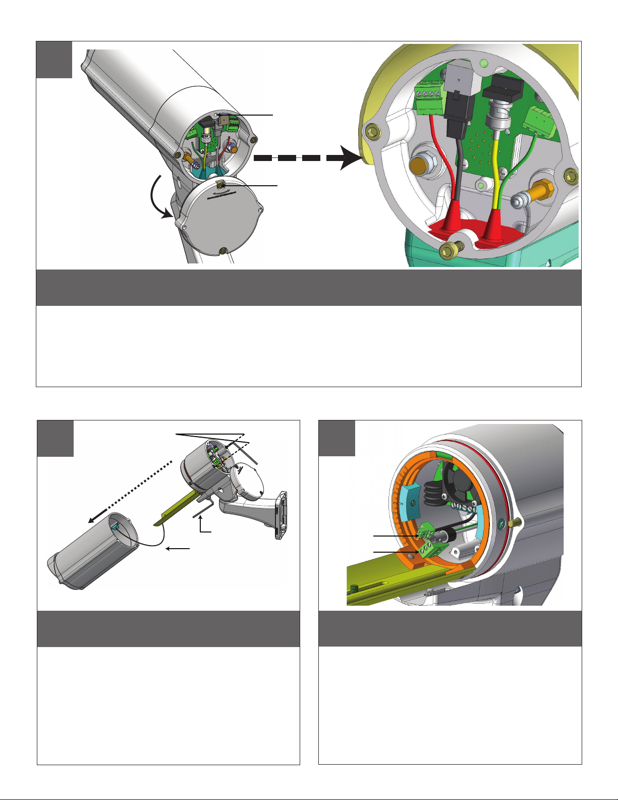
In order to rotate the rear cover, slightly loosen the screw marked (A) and completely loosen the screw marked (B).
Then make all of the nessecary wiring connections.
• Conecte la tierra entrante con el poste de tierra según lo demostrado.
• Reliez la terre entrante au poteau au sol comme montré.
• Schließen Sie ankommenden Boden an Grundpfosten an, wie gezeigt.
• Conecte a terra entrante ao borne à terra como mostrado.
• Colleghi la terra ricevuta all'alberino al suolo come indicato.
(A- Slightly loosen)
(B- Completely loosen)
9
Use provided Key to remove the front part of the housing.
• El uso proporcionó llave para quitar la parte delantera de la cubierta.
• L'utilisation a fourni la clef pour enlever la partie avant du logement.
• Gebrauch lieferte Schlüssel, um das Vorderteil des Gehäuses zu entfernen.
• O uso forneceu a chave para remover a parte dianteira da carcaça.
• L'uso ha fornito la chiave per rimuovere la parte anteriore dell'alloggiamento.
Lanyard Cable
Key (B) 1 lower screw
(A)
(A)
(A) 2 long screws
Use Force to Separate the Housing
Reference inside view for showing board, ying cables and
attached connectors.
• Reérase dentro de la visión para demostrar el tablero, los cables que vuelan y los
conectadores atados.
• Mettez en référence à l'intérieur de la vue pour montrer le conseil, les câbles volants et
les connecteurs attachés.
• Beziehen Sie innerhalb der Ansicht für das Zeigen des Brettes, der iegenden Kabel und
der angebrachten Verbindungsstücke.
• Proveja dentro da vista para mostrar a placa, cabos de voo e conectores unidos.
• Riferimento all'interno della vista per la mostra bordo, i cavi volanti e dei connettori allegati.
Cable
Connectors
10 11

Connect the network cable from the
midspan to the connector that is labeled
“To Network” connect the camera to the
connector labeled “To Camera”. When
power is applied the “Heat” LED will turn
ON for 5 seconds. 60 seconds the blower
will start.
• Conecte el cable de red del centro de la luz en el conector
que tiene la etiqueta "Para Red", conecte la cámara al
conector con la etiqueta "Para la cámara". Cuando la
energía se aplica el "calor" LED se encenderá durante 5
segundos. 60 segundos, el ventilador se enciende.
• Branchez le câble réseau de la mi-portée sur le connecteur
qui est étiqueté «Pour Réseau" connecter l'appareil photo
au connecteur marqué "à la caméra". Lorsqu'une tension
est appliquée la "chaleur" LED s'allume pendant 5
secondes. 60 secondes le ventilateur démarre.
• Schließen Sie das Netzwerkkabel aus dem Midspan an
den Anschluss, die den Namen "Zum Network" schließen
Sie die Kamera an den Anschluss mit der Aufschrift "Zur
Kamera". Wenn die Macht der "Heat" wird angewendet
LED für 5 Sekunden einzuschalten. 60 Sekunden das
Gebläse startet.
• Conecte o cabo de rede do midspan ao conector que
é rotulado de "rede" conectar a câmera ao conector
identicado como "Para Camera". Quando a energia
é aplicada a "Heat" LED irá acender por 5 segundos.
60 segundos, o ventilador começará.
• Collegare il cavo di rete dal midspan al connettore che
viene etichettato come "alla rete" collegare la fotocamera
al connettore etichettato "Per Camera". Quando il potere
è applicato il "Heat" LED si accende per 5 secondi. 60
secondi il ventilatore si avvia.
To Network To Camera
Press the Calibration button for one second.
Both the Test and Heat LED will turn ON.
Once the unit has been successfully
calibrated, the Test and Heat LED will turn
OFF. Once this is complete the Heat LED
will turn ON only if the heater is ON.
• Pulse el botón de calibración durante un segundo. Tanto la
prueba y el calor se encenderá. Una vez que la unidad ha
sido calibrado correctamente, la prueba y el calor del LED
se apagará. Una vez que se trata de completar el calor se
encenderá sólo si el calentador está encendido.
• Appuyez sur le bouton d'étalonnage pour une seconde.
Tant le test et la chaleur LED s'allume. Une fois l'appareil
a été étalonné avec succès, le test et la chaleur LED
s'éteindra. Une fois cette opération terminée, la chaleur
LED s'allume que si le chauffage est allumé.
• Drücken Sie die Taste Kalibrierung für eine Sekunde.
Sowohl der Test-und Wärme-LED leuchtet auf. Sobald
das Gerät erfolgreich kalibriert wurde, wird die Test-und
Wärme-LED auszuschalten. Sobald dies abgeschlossen
ist die Wärme-LED leuchtet auf, wenn die Heizung an ist.
• Pressione o botão de calibração para um segundo.
Tanto o teste como calor LED acenderá. Uma vez que
o aparelho foi calibrado com sucesso, o teste e calor
LED apaga-se. Uma vez que este é completar o calor
LED acenderá se o aquecedor está ligado.
• Premere il pulsante di calibrazione per un secondo. Sia
il test e di calore LED si accende. Una volta che l'unità è
stata correttamente calibrata, il collaudo e calore LED si
spegne. Una volta che questo è completare il calore LED
si accende solo se il riscaldatore è ON.
Test LED
Heat LED
Calibration
Button
D
D
When pressurizing unit be sure to set the gauge or regulator
slightly above the housing pressure target of 5-7psi (0.35-0.5bar).
• Al presurizar la unidad esté seguro de jar el calibrador o el regulador levemente
sobre la blanco de la presión de la cubierta de 5-7psi (0.35-0.5bar).
• En pressurisant l'unité soyez sûr de placer la mesure ou le régulateur légèrement
au-dessus de la cible de pression de logement de 5-7psi (0.35-0.5bar).
• Wenn Sie Maßeinheit unter Druck setzen, seien Sie sicher, die Lehre oder den
Regler über das Gehäusedruckziel von 5-7psi (0.35-0.5bar) etwas einzustellen.
• Ao pressurizar a unidade seja certo ajustar ligeiramente o calibre ou o regulador
acima do alvo da pressão da carcaça de 5-7psi (0.35-0.5bar).
• Nel pressurizzare l'unità sia sicuro regolare un po'il calibro o il regolatore sopra
l'obiettivo di pressione dell'alloggiamento di 5-7psi (0.35-0.5bar).
PSI
0
50
100
150
200
250
300
Nitrogen
Tank
Hose
Regulator
Air Chuck
580
Fitting
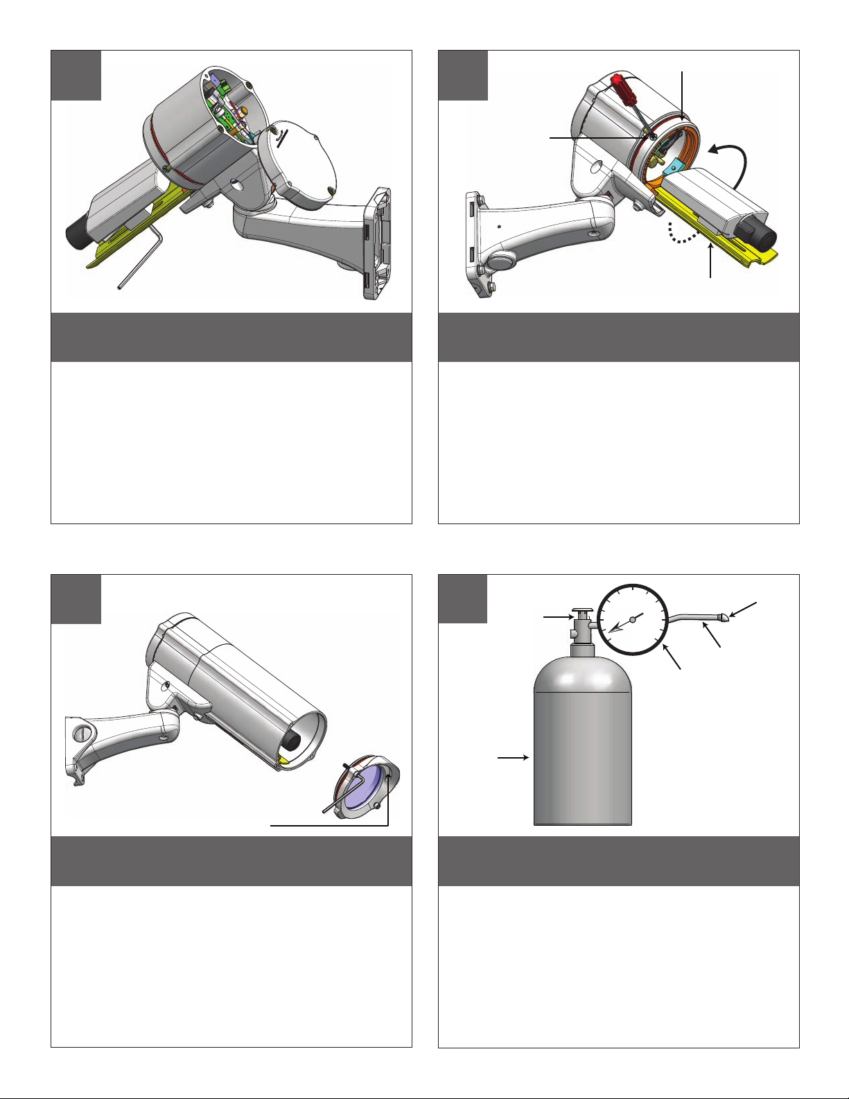
Install the camera using provided screws and rubber spacer, to
center lens (if needed).
• Instale la cámara usando los tornillos proporcionados y el espaciador de goma, a la lente de
centro (si es necesario).
• Installez l'appareil-photo utilisant les vis fournies et l'entretoise en caoutchouc, sur l'objectif
central (si nécessaire).
• Bringen Sie die Kamera unter Verwendung der zur Verfügung gestellten Schrauben und der
Gummidistanzscheibe, zum Mittelobjektiv an (wenn erforderlich).
• Instale a câmera usando os parafusos fornecidos e o espaçador de borracha, à lente center
(se necessário).
• stalli la macchina fotograca usando le viti fornite ed il distanziatore di gomma, all'obiettivo
concentrare (se necessario).
Loosen the screws shown on the picture and turn the camera
sled ring to the desired angle and re-tighten.
• Aoje los tornillos demostrados en el cuadro y dé vuelta al anillo del trineo de la cámara
al ángulo deseado y vuélvalo a apretar.
• Desserrez les vis montrées sur l'image et tournez l'anneau de traîneau d'appareil-photo
à l'angle désiré et le resserrez.
• Lösen Sie die Schrauben, die auf der Abbildung gezeigt werden und drehen Sie den
Kameraschlittenring zum gewünschten Winkel und ziehen Sie wieder an.
• Afrouxe os parafusos mostrados no retrato e gire o anel do trenó da câmera para o ângulo
desejado e reaperte-o.
• Allenti le viti indicate sull'immagine e giri l'anello della slitta della macchina fotograca
nell'angolo voluto e riserri.
Screw
Camera Sled Ring
Camera Sled
12
The front window can be removed in case the lens
requires adjustment.
• La ventana delantera puede ser quitada en caso de que la lente requiera el ajuste.
• La fenêtre avant peut être enlevée au cas où l'objectif exigerait l'ajustement.
• Das vordere Fenster kann entfernt werden, falls das Objektiv Justage erfordert.
• A janela dianteira pode ser removida caso que a lente exige o ajuste.
• La nestra anteriore può essere rimossa nel caso l'obiettivo richieda la registrazione.
HAND HOLD
13
14 15
Future Maintenance Pressurize the Unit (NOT required for the Dust Tight Unit)

Depress the ll valve. Drain all air
from the housing and repeat 3 times
to remove all moisture.
• Presione la válvula del terraplén. Salga todo el aire
de la cubierta y de la repetición 3 veces de quitar
toda la humedad.
• Enfoncez la valve de sufsance. Évacuez tout l'air le
logement et la répétition 3 fois d'enlever toute
l'humidité.
• Drücken Sie das Fülleventil nieder. Lassen Sie alle
Luft aus dem Gehäuse und der Wiederholung 3mal,
alle Feuchtigkeit zu entfernen ab.
• Comprima a válvula da suciência. Saia todo o ar da
carcaça e da repetição 3 vezes remover toda a
umidade.
• Deprima la valvola del materiale di riempimento.
Tolga tutta l'aria dall'alloggiamento e dalla
ripetizione 3 volte rimuovere tutta l'umidità.
Depress to Purge
Pressure Fill Schraeder Valve
Pressure Fill Schraeder Valve
Air Chuck
Place the air chuck on the ll valve
and begin lling until pressure relief
valve opens.
• Coloque la tirada del aire en la válvula del tanque y
comience a llenar hasta que la válvula de descarga
de presión se abra.
• Placez le mandrin d'air sur la valve de réservoir et
commencez à remplir jusqu'à ce que la valve de
décompression s'ouvre.
• Setzen Sie die Luftklemme auf das Behälterventil
und fangen Sie an zu füllen, bis Druckablassventil
sich öffnet.
• Coloc o mandril do ar na válvula do tanque e
comece a encher-se até que a válvula de escape de
pressão abra.
• Disponga il mandrino dell'aria sulla valvola del carro
armato e cominci a riempire no a che la valvola
limitatrice della pressione non si apra.
Over Relief Valve
(5-7psi)
Pressurize the Unit Cont.
16
17

3
6
13
14
11
17
2
1
11
7
4
10
8
12
16
5
15
Replacement Parts List
PFH10
DESCRIPTIONPART #
1 RPVL3857 BACK COVER
2RPVL3863 BACK COVER GASKET
3RPVALV12 TANK VALVE
4 RPCA3682 CONNECTION BOARD
5 RPPFHPCK HARDWARE PACKET
6 RPVALV08 PRESSURE RELIEF VALVE
7 RPVL2968 HOUSING BODY
8 RPGK3880 WALL MOUNT GASKET
9 RPVL3858 HOUSING BRACKET
10 RPFTM2425G WALL MOUNT BRACKET
11 RPRSORG24 HOUSING ORING
12 RPVL3860 HOUSING NUT
13 RP76VL2015 PC BOARD
14 RPVL2969 CAMERA SLED ASSEMBLY
15 RPVL2965 HOUSING ASSEMBLY
16 RPVL3888 LANYARD SLED
17 RPVL2972 FRONT WINDOW ASSEMBLY
9
PSI
0
5
10
15
20
25
30
Fill Valve
Over - Pressure Relief Valve
Connectors
Pressure Gauge
NOT INCLUDED
Air Chuck
After purging and relling, check
the housings pressure. It should be
around 5-7psi (0.35-0.5bar).
• Después de purgar y de rellenar, compruebe la
presión de las cubiertas. Debe estar alrededor de
5-7psi (0.35-0.5bar).
• Après la purge et le remplissage, vériez la pression
de logements. Elle devrait être autour de 5-7psi
(0.35-0.5bar).
• Nachdem Sie bereinigt haben und wieder gefüllt
haben überprüfen Sie den Gehäusedruck. Er sollte
um 5-7psi (0.35-0.5bar) sein.
• Após a remoção e o reenchimento, veric a pressão
das carcaças. Deve ser em torno de 5-7psi
(0.35-0.5bar).
• Dopo l'eliminazione dell'inceppo ed il riempimento,
controlli la pressione degli alloggiamenti. Dovrebbe
essere intorno a 5-7psi (0.35-0.5bar).
18
This manual suits for next models
6
Table of contents
Other Moog Camera Accessories manuals


Popular Camera Accessories manuals by other brands


Sony
Sony VCT-EXC1 quick start guide

Kaiser Fototechnik
Kaiser Fototechnik SmartCluster Vario 8 operating instructions

Atomos
Atomos SHINOBI 7 quick start guide

Axis
Axis P3343-VE installation guide

Digital Noise Reduction
Digital Noise Reduction STAR LIGHT ES-6030ESHDV23712 operating manual

Hitachi
Hitachi BCL1030M quick start guide