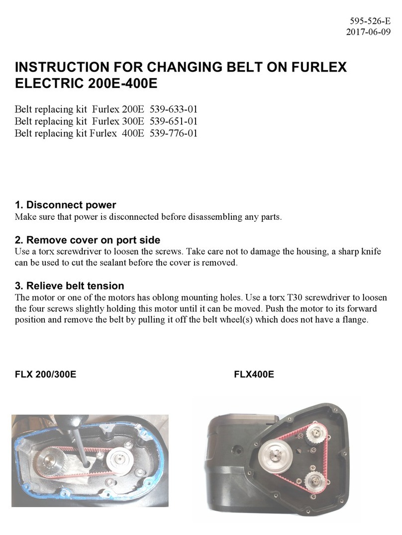
Selden Furlex 200 S User manual

Assembly manual for
Furlex
200 S
,
300 S,
400 S & 500 S
with rod forestay
595-111-E
2004-12-15
RODSTAY

2
T 40
T 30 –
–
This information must be followed to avoid damage to the system and the risk of
personal injury. The 5-year guarantee on the Furlex-system is only valid if the system
is assembled and operated correctly according to the manual.
1 Introduction
PLEASE read the entire manual prior to assembly!
Seldén Mast AB guarantees the Furlex-system for 5 years. The guarantee covers faults arising from
defective design, materials or workmanship.
The guarantee is only valid if the Furlex-system is assembled, operated and maintained in accordance
with this manual and is not subjected to loads in excess of those indicated in the brochure and instruc-
tions.
If the system is repaired by anyone other than Seldén Mast AB or one of our authorized dealers, the
guarantee ceases to be valid.
Seldén Mast AB reserves the right to alter the content and design without prior warning.
1.1 The manual
This manual covers assembly of the rod forestay and replaces the corresponding headings in the
”Manual Furlex 200 S & 300 S” (ref. no. 595-104-E). resp ”Manual Furlex 400 S & 500 S” (ref. no.
595-116-E).
These instructions is included in Furlex box. See ”Contents” on Page 3.
It is very important to read both manuals and note any cross references.
All safety-related information is indicated by the following symbol:
The manual covers four different Furlex sizes, 200 S, 300 S, 400 S and 500 S. The assembly pro-
ceedings varies on some points between the different sizes. This is marked in the manual.
The model designation can be found on the line drum top.
All dimensions specified in the manual are in millimetres (mm) unless otherwise indicated.
The screws used for the halyard swivel and lower bearing assembly have a Torx or Allen socket. The
requisite spanners are included with the Furlex. The table below gives the relevant screw sizes and
corresponding sockets.
Skrew Size Torx Socket Allen Socket
M 8
M 6
M 5
M10
M12
T 25
–
–Fig: 1.1.a
–
8 mm
10 mm Fig: 1.1.b

3
Page
1 Introduktion
1.1 The manual 2
1.2 Product information 4
1.3 Compatible sizes 6
MONTERING
2 Checklist
2.1 Furlex box 7
2.2 Foil pack 9
2.3 Joining sleeve pack 10
2.4 Tools 10
3 Assembly preparations
3.3.2 Dimensions of top eye terminal 11
3.5 Calculating the length of the
rod forestay 12
3.5.1 Calculation table 1:
Length of rod forestay 12
3.6 Calculating the length of
the luff extrusion 13
3.6.1 Calculation table 2:
Length of luff extrusion 13
4 Assembly of the Furlex-system
4.1 Assembly of the rod forestay 16
4.2 Assembly of the luff extrusion
200 S & 300 S 17
4.2 Assembly of the luff extrusion
400 S & 500 S 19
4.3 Fitting the line drum
and line guide -
200 S & 300 S 24
400 S & 500 S 25
17 Dismantling
17.1 Halyard swivel 27
17.7 Luff extrusion system 27
17.8 Top guard 27
Contents

4
When the original Furlex was introduced in 1983, it was not a pioneering project. The design included
features which improved on other manufacturers’ products to increase performance, function and reli-
ability. The first systems sold are still functioning well, providing ample proof of the design’s effec-
tiveness and long-term staying power. Furlex quickly became the market leader, a position it still occu-
pies today. Our success can also be put down to how we select a system for a specific yacht. First we
calculate the boat’s righting moment, which is the function of its displacement, ballast, beam and
draught. Then we use righting moment in combination with the rig type to calculate its power when
sailing, and the likely loads on the Furlex system.
Furlex is only sold through authorized local dealers who are able to cover all service requirements for
the customer, including assistance with assembly, the modification of sails or the production of new
sails.
This new Furlex model range incorporates improvements based on our extensive experience, and rep-
resents the very latest development of the jib furling and reefing concept.
Furlex is supplied as a complete assembly kit containing all the components required.
The ball-bearing system of the halyard swivel features a load distribution facility, a unique patented
system which distributes loads over the entire ball race. This permits smoother furling and consid-
erably reduces bearing wear.
Furlex can be supplied with an optional integral rigging screw.
The Furlex luff section has the same dimensions over its whole length. The entire luff is furled in
an even roll, right down to the tack of the sail. This is a requirement for satisfactory sail shape
when reefed.
The tack ring’s ”free turn” flattens out the sail, promoting an efficient shape when reefed.
Furlex is suited to both cruising and racing. The line drum and line guide are easy to remove if you
want to utilize the entire forestay length for racing.
The luff section has two luff grooves, allowing two jibs to be goose-winged when running down-
wind and facilitating fast sail changes for racing yachtsmen.
The aluminium extrusion is insulated from the forestay over its whole length. Furlex 200 S, 300 S
and 400 S has the extrusion joining sleeves are also are insulated internally to prevent wear and
corrosion. The clearance between the forestay and the joining sleeve on the 500 S is sufficiently
large to be able to omit the insulation.
The line guide fitting centres the line as it is wound onto the drum, and the flexible internal line
guard maintains light pressure on the line to ensure even distribution on the drum.
Furlex is manufactured by Seldén Mast, the world’s leading manufacturer of masts and rigging sys-
tems.
1.2 Product information
Follow the instructions carefully when fitting.

5
3
1
2
5
10
11
8
4
6
7
9
19
18
20
22
21
12
13
14
15
16
17
4
1. Forestay eye terminal
2. Top guard
3. Halyard swivel
4. Snap shackle/D-shackle
5. Luff extrusion
6. Distance tube
7. Joining sleeve
8. Long joining sleeve
9. Sail feeder
10. Sail feeder connector
11. Connecting plate
12. Lower bearing assembly
13. Tack ring
14. Adapter
15. Terminal part or
rigging screw
16. Fork / fork toggle
17. Line drum half
18. Line guard housing
19. Line guard
20. Line guard bracket
21. Line guide fitting
22. Locking block

6
1.3 Compatible sizes
1) As the male part of this rod terminal type/size is too large to pass through the luff extrusions, the
rod forestay can only be cold-headed at its upper terminal end after the stay has been pulled through
the assembled extrusions. The extrusion must be made 200 mm (8”) shorter than the stay at the top
to make room for the cold-heading machine. Consequently the luff extrusions length and available
sail space is reduced. The system has to be manufactured by the rod manufacturer, which may give
rise to transportation problems.
2) The upper eye terminal must be of the MNY type.
–••
Limits imposed by strength
of furling system
Partial
rig
Furlex
8.0
Forstay
dim.
300 S
Navtec OYS2
(Riggarna)
BSI
Rod diameter
Max. righting
moment at
30° heel (Nm)
Mast-
head
rig
Partial
rig
Mast-
head
rig
75.000
190.000
250.000
14
28
38
15
30
40
200 S
200 S
200 S
300 S
-8 (ø 5.7 mm)
-10 (ø 6.4 mm)
-12 (ø 7.1 mm)
-15 (ø 7.5 mm) 1
-12 (ø 7.1 mm)
-15 (ø 7.5 mm)
-17 (ø 8.4 mm)
-22 (ø 9.5 mm)
400 S 12 mm
10 mm
8 mm
8 mm
7 mm
6 mm
-30 (ø 11.1 mm)
-30 (ø 11.1 mm)
400 S 14 mm -40 (ø 12.7 mm)
500 S 16 mm
-40 (ø 12.7 mm)
-48 (ø 14.3 mm)
37.000
70.000
180.000
230.000
40.000 7.5
Approximate
displacement
(tons)
•••
•••
•–•
•–•
–••
•–•
•••
•••
•––
•••
••–
•••

7
400 S/Ø12
Rigging screw adapter
Wire terminal (200 S & 300 S with spacer
bush) or Furlex rigging screw function.
(Depends on which type ordered.)
Halyard swivel with snap shackle/-
D-shackle
Lower bearing assembly with snap
shackle/D-shackle
2x line drum halves
(one with furling line end lock
200 S & 300 S)
Line guide fitting
2 Checklist
2.1 Furlex box
ASSEMBLY

8
500 S: Halyard leads are not included.
A halyard sheave box must be used for this
model. (See ”Manual Furlex 400 S & 500 S”,
ref no. 595-116-E. Chap. 5.2, Fig: 5.2.a, page 24.)
300 S:
2 halyard leads 508-128 with
insulator sheets incl. 6 screws
Drill bit Ø 5.3 mm (7/32”)
Furling line
200 S:
2 halyard leads 508-159 with
insulator sheets incl. 4 screws
Drill bit Ø 5.3 mm (7/32”)
200 S & 300 S: Torx spanner set
400 S & 500 S:
Torx spanner set + Allen keys 8 (5/16”)
and 10 mm (3/8”).
200 S:
4 stanchion blocks 538-971-02
300 S:
4 stanchion blocks 538-210-01
+ 1 x 538-971-01
400 S & 500 S:
6 stanchion blocks 538-210-01
Locking adhesive
Lubricating grease
Line drum casing
Line guide locking block
400 S:
2 halyard leads 508-128 with
insulator sheets incl. 6 screws
Drill bit Ø 5.3 mm (7/32”)

9
200 S, 300 S and 400 S:
2400 mm (94 1/2”) luff extrusions with slot-
ted distance tubes (number dependent
on length ordered.)
500 S: 4800 mm (189”) luff extrusions with
distance tube + joining sleeve (number
dependent on length ordered).
200 S, 300 S and 400 S: Sail feeder (sail
feeder + sailfeeder connector)
500 S: The sail feeder is cut into the
1000 mm luff extrusion on this model.
One 1000 mm (39 3/8”) luff extrusion
One 2000 mm (78 3/4”) luff extrusion
with slotted distance tube
2.2 Foil pack
Top guard incl. 2 screws
Instructions
Spare parts list
Certificate of guarantee
200 S, 300 S and 400 S:
1 short connecting plate for each
2400 mm (94 1/2”) luff extrusion
200 S, 300 S and 400 S:
1 long connecting plate (for sail feeder)
500 S: 1 short connecting plate for each
4 800 mm luff extrusion
200S & 300 S:
1 locking pin Ø 3 x 25 (Ø 1/8” x 1”) for
1000 mm (39 3/8”) luff extrusion
400 S & 500 S:
2 x bushes for 1000 mm (39 3/8”) luff extrusion

10
Tools needed for assembly:
Screwdriver
Hacksaw
2 adjustable spanners
“Polygrip” pliers
Adhesive tape
File
Marker pen (water-proof)
Torx spanners (included in Furlex package)
Steel measuring tape (30 m) (100”)
Knife
200 S, 300 S och 400 S:
For halyard leads:
Heavy-duty Philips screwdriver
Drill
Drill bit Ø 5.3 mm (7/32”)
(included in Furlex package)
2.4 Tools
1 long joining sleeve with insulator
(not 500 S)
Short joining sleeves with insulators
(not 500 S)
(number dependent on length ordered)
Socket
1 seat for rod forestay in lower bearing
assembly
500 S: Socket and seat forms one part
Instructions
2.3 Joining sleeve pack
The joining sleeve pack and foil pack may be delivered as a combined
package.
400 S & 500 S:
Bearing plug

-8 (ø 5.7 mm)
11
3 Assembly preparations
3.1 Forestay attachment –
guiding principle
3.2 Mast attachment
3.3 Deck attachment
3.3.1 Dimensions of lower
bearing assembly
See “Manual Furlex 200 S & 300 S”
(ref. no. 595-104-E)
resp. ”Manual Furlex 400 S & 500 S”
(ref. no. 595-116-E).
Fig: 3.3.2.a
3.3.2 Dimensions of top eye terminal
3.3.3 Toggle dimensions
3.4 Assembly below deck
TEL
TED
1) Type MYE cannot be used.
}
}
TET
See ”Manual Furlex 200 S & 300 S”
(ref. no. 595-104-E) resp.
”Manual Furlex 400 S & 500 S”
(ref. no. 595-116-E).
OYS
(Riggarna)
––––––
Rod diameter BSI
TET TED TET
11.0 mm
(7/16”)
•
•
•
•
•
•
•
-40 (ø 12.7 mm)
•
•
•
•
•
•
•
•
14.0 mm
(9/16”)
-10 (ø 6.4 mm)
TET TED TET
-12 (ø 7.1 mm)
-15 (ø 7.5 mm)
-17 (ø 8.4 mm)
-22 (ø 9.5 mm)
-30 (ø 11.1 mm)
-48 (ø 14.3 mm)
108 mm
(4 1/4”)
87 mm
(3 7/16”)
10.0 mm
(13/32”)
11.3 mm
(7/16”)
71 mm
(2 13/16”)
12.4 mm
(1/2”)
13.1 mm
(17/32”)
72 mm
(2 27/32”)
12.9 mm
(1/2”)
76 mm
(3”)
12.4 mm
(1/2”)
13.1 mm
(17/32”)
72 mm
(2 27/32”)
16.0 mm
(5/8”)
89 mm
(3 1/2”)
15.7 mm
(5/8”)
––
16.3 mm
(5/8”)
82 mm
(3 7/32”)
–
15.7 mm
(5/8”)
–
––––
16.3 mm
(5/8”)
82 mm
(3 7/32”)
16.0 mm
(5/8”)
19.2 mm
(3/4”)
18.8 mm
(3/4”)
19.4 mm
(3/4”)
99 mm
(3 29/32”)
20.0 mm
(25/32”)
22.4 mm
(7/8”)
21.8 mm
(7/8”)
22.6 mm
(29/32”)
111 mm
(4 3/8”)
23.0 mm
(29/32”)
25.7 mm
(1”)
123 mm
(4 27/32”)
25.1 mm
(1”)
22.8 mm
(29/32”)
122 mm
(4 13/16”)
26.0 mm
(1 1/32”)
14.0 mm
(9/16”)
10.0 mm
(13/32”)
11.0 mm
(7/16”)
14.0 mm
(9/16”)
14.0 mm
(9/16”)
17.0 mm
(21/32”)
19.5 mm
(3/4”)
22.0 mm
(7/8”)
25.0 mm
(1”)
16.0 mm
(5/8”)
11.3 mm
(7/16”)
13.1 mm
(17/32”)
16.0 mm
(5/8”)
16.0 mm
(5/8”)
19.3 mm
(3/4”)
22.6 mm
(29/32”)
25.7 mm
(1”)
29.0 mm
(1 1/8”)
80 mm
(3 5/32”)
62 mm
(2 7/16”)
68 mm
(2 11/16”)
86 mm
(3 3/8”)
80 mm
(3 5/32”)
100 mm
(3 15/16”)
115 mm
(4 17/32”)
129 mm
(5 1/16”)
146 mm
(5 3/4”)
29.0 mm
(1 1/8”)
139 mm
(5 15/32”)
28.2 mm
(1 1/8”)
29.0 mm
(1 1/8”)
127 mm
(5”)
Navtec (Marine Eye)
TET TED TET
(MYN)1(RFE)
•
•
•
•
•
•
•
•
•

400 S
•
•
•
–
•
–
•
•
•
•
•
•
200 S
FL
Without
rigg.
screw
12
3.5 Calculating the length of the rod forestay
1. Determine the rake of the mast with the fore-/backstay tensioned.
2. Slacken the backstay as much as possible, but make sure that any rigging screw is not unscrewed
so far that the threads are no longer visible “on the inside”. The forestay setting should not be
adjusted. However, if the forestay rigging screw setting has to be adjusted, measure the length or
mark the original setting.
3. Pull the masthead forward using the genoa halyard. Secure the halyard using a ”D” shackle or tie it
to a strong deck fitting. For safety reasons, do not use the halyard snap shackle.
Always use a strong “D” shackle or tie the halyard!
4. Take down the forestay. (If the rigging screw was adjusted, return it to its original setting.)
5. Measure the forestay length (FL) with just enough tension to keep it straight.
6. Enter the measurement in ”Calculation Table 1” below, under the heading “Your forestay”, on the
row marked FL.
7. Calculate the new rod length WL in ”Calculation Table 1”. Refer to the column marked ”exam-
ple” to see how this is done.
•
•
–
•
–
•
–
•
•
•
•
•
•
•
•
•
•
•
•
•
•
•
–
•
3.5.1
500 S
-40 (ø 12,7 mm)
Rod diameter
T
Calculation Table 1: Length of rod forestay
Existing forestay length (FL),
including rigging screw (See Fig. 3.5.a)
=
+
12.810
See fig 3.5.a
13.000
If links or extra toggles are to be used,
deduct this length (H) from FL. (See table 3.3.3.)
=
Your
forestay
Example
(Navtec -8)
with rigging
screw
50% extended
H
WL
Deduction for lower wire terminal:
-- 190
=13100
Addition for cold-heading of rod forestay
(acc. to rod supplier’s data) +
Deduction for top terminal (acc. to rod supplier’s data) --
Cutting measurement of rod =
190
-48 (ø 14,3 mm)
With rigg.
screw
325 mm
(12 7/8”)
190 mm
(7 1/2”)
325 mm
(12 7/8”)
190 mm
(7 1/2”)
230 mm
(9 1/16”)
130 mm
(5 1/8”)
230 mm
(9 1/16”)
130 mm
(5 1/8”)
235 mm
(9 1/4”)
130 mm
(5 1/8”)
235 mm
(9 1/4”)
130 mm
(5 1/8”)
300 S
-15 (ø 7,5 mm)
-12 (ø 7,1 mm)
-22 (ø 9,5 mm)
-17 (ø 8,4 mm)
-8 (ø 5,7 mm) 190 mm
(7 1/2”)
BSI
Navtec OYS
(Riggarna)
-10 (ø 6,4 mm)
-12 (ø 7,1 mm)
-15 (ø 7,5 mm)
110 mm
(4 5/16”)
110 mm
(4 5/16”) 190 mm
(7 1/2”)
110 mm
(4 5/16”) 190 mm
(7 1/2”)
110 mm
(4 5/16”) 190 mm
(7 1/2”)
-40 (ø 12,7 mm)
-30 (ø 11,1 mm) 190 mm
(7 1/2”)
325 mm
(12 7/8”)
190 mm
(7 1/2”)
325 mm
(12 7/8”)

200 S
300 S
C+D
400 S
C
Your
extrusion
13
3.6.1
12.810
1.270
11.540
9.600
1.940
WL Length of new rod forestay (as per ”Calculation Table 1”)
3.6 Calculating the length of the luff extrusion
1. Insert the length of the new rod forestay (WL) as calculated in
”Calculation Table 1” into ”Calculation Table 2”, in the row marked WL.
2. Calculate the number of full-length extrusions and the length of the top extrusion.
Fixed deduction (A + B):
Check that length of terminal part of stay matches the measurement in 3.3.2.
A+B
-
=1395 =
-12.810
C+D=
(4 sections)
-
500 S
C
Deduct from the C measurement: 200/300 S: 400 mm (15 3/4”)
400 S: 700 mm (27 9/16”)
500 S: 2800 mm (110”)
Add to the D measurement: 200/300 S: 400 mm (15 3/4”)
400 S: 700 mm (27 9/16”)
500 S: 2800 mm (110”)
D
Max. no. of 2400 mm (94 1/2”) extrusions whitch together
are shorter than C+D: [ ............x 2400 = C ] C=
Length of top extrusion =
The top extrusion is normally cut from the 2000 mm (78 3/4”)(400 S 1700 mm
(67”)) extrusion. Round the edges of the cut end using a file.
If the top extrusion is shorter than 400 mm (15 3/4”) (200/300 S), 700 mm (27
9/16”) (400 S), 1000 mm (39 3/8”) (500 S), the joint will be too near the top. In
this case replace the uppermost full-length 2400 mm (500 S: 4800 mm) extru-
sion with the 2000 mm (78 3/4”) (400 S: 1700 mm (67”)) extrusion. In this way
the joint is moved 400 mm (15 3/4”) (400 S: 700 mm (27 9/16”); 500 S: 2800 mm
(110”)) down the stay.
Adjust the C and D measurements as follows:
-1395
Max. no. of 4800 mm (189”) extrusions whitch together
are shorter than C+D: [ ............x 4800 = C ] C= -1395
== 2115
Cont. on next page
Calculation Table 2: Length of luff extrusion
Example
(Navtec -8)
with
rigging screw
50% extended
1310 mm
(51 1/2”)
•
•
–
•
–
•
–
•
•
•
•
•
1310 mm
(51 1/2”)
•
•
•
–
•
–
•
•
•
•
•
•
•
•
•
•
•
•
•
•
•
•
–
•
Rod diameter OYS
(Riggarna)
BSI
With
rigg.
screw
Without
rigg.
screw
Navtec
With
rigg.
screw
1310 mm
(51 1/2”)
1340 mm
(52 3/4”)
1290 mm
(50 3/4”)
1290 mm
(50 3/4”)
1290 mm
(50 3/4”)
Without
rigg.
screw
1320 mm
(52”)
1270 mm
(50”)
1320 mm
(52”)
1270 mm
(50”)
1320 mm
(52”)
1270 mm
(50”)
––
1400 mm
(55 1/8”)
1340 mm
(52 3/4”)
––
1400 mm
(55 1/8”)
1400 mm
(55 1/8”)
1340 mm
(52 3/4”)
1340 mm
(52 3/4”)
1340 mm
(52 3/4”)
1340 mm
(52 3/4”)
1340 mm
(52 3/4”)
1290 mm
(50 3/4”)
1340 mm
(52 3/4”)
1340 mm
(52 3/4”)
1410 mm
(55 1/2”)
1410 mm
(55 1/2”)
1340 mm
(52 3/4”)
1410 mm
(55 1/2”)
1340 mm
(52 3/4”)
1410 mm
(55 1/2”)
1340 mm
(52 3/4”)
1450 mm
(57”)
1395 mm
(55”)
1395 mm
(55”)
1395 mm
(55”)
1310 mm
(51 1/2”)
1450 mm
(57”)
1340 mm
(52 3/4”)
1470 mm
(58”)
1380 mm
(54 1/2”)
1470 mm
(58”)
1380 mm
(54 1/2”)
1395 mm
(55”)
-40 (ø 12,7 mm)
-48 (ø 14,3 mm)
500 S
-15 (ø 7,5 mm)
-12 (ø 7,1 mm)
-22 (ø 9,5 mm)
-17 (ø 8,4 mm)
-8 (ø 5,7 mm)
400 S
-10 (ø 6,4 mm)
-12 (ø 7,1 mm)
-15 (ø 7,5 mm)
-40 (ø 12,7 mm)
-30 (ø 11,1 mm)

14
Fig:3.5.a
FL = existing forestay length
A
E
CB
D
WL T
S

300 S
-15 (ø 7,5 mm)
E = D - 150 mm (6”)
Calculation Table 2: Length of luff extrusion, cont.
15
3.6.1
Deduction: -
Cut the distance tube for the top extrusion in accordance
with the following fixed deduction:
E
Length of distance tube E =
-
=
Your
extrusion
Example
(Navtec -8)
with
rigging screw
50% extended
=
100
1.840
•
•
–
•
–
•
–
•
•
•
•
•
200 S
Rod diameter
•
•
•
–
•
–
•
•
•
•
•
•
E = D - 100 mm (4”)
E = D - 125 mm (5”)
E = D - 150 mm (6”)
-40 (ø 12,7 mm)
-48 (ø 14,3 mm)
500 S
-15 (ø 7,5 mm)
-12 (ø 7,1 mm)
-22 (ø 9,5 mm)
-17 (ø 8,4 mm)
-8 (ø 5,7 mm)
400 S
-10 (ø 6,4 mm)
-12 (ø 7,1 mm)
-40 (ø 12,7 mm)
-30 (ø 11,1 mm)
Navtec OYS
(Riggarna)
BSI
•
•
•
•
•
•
•
•
•
•
–
•

16
4 Assembly of the Furlex-system
4.1 Assembly of the rod forestay
Assembly is carried out by the rod supplier. Apart from the actual rod forestay, only the joining sleeve
pack is required.
1. Measure the length of the rod forestay. (The WL measurement and corrections for the length of the
top terminal and the cold-headed head at the lower end have been calculated in
”Calculation Table 1”.)
2. Cut the stay.
3. Form the head for the upper terminal and fit it. The eye part must only be fitted temporarily. Fasten
any locking screws and attach the instructions for permanent assembly of the eye part.
4.
Fig: 4.1.a
400 S
500 S
Bearing plug
5. Cold-head the head of the rod forestay for the lower bearing part.
6. Pack the stay, enclosing the completed ”Calculation Tables 1 & 2”.
Thread the joining sleeve sections on in the following order counting from the top:
•Short joining sleeves with accompanying insulation tubes. The number must correspond to the
number of 2400 mm (94 1/2”) extrusions. (500 S: 48 000 mm). See ”Calculation Table 2”,
row C, section 3.6.1.
•The long joining sleeve with accompanying insulation tube. Locking pin hole (200 S & 300 S)
towards socket.
•400 S & 500 S: Bearing plug. Be sure to turn it as shown in the diagram.
•The socket. Be sure to turn it as shown in the diagram.
•Seat. Be sure to turn it as shown in the diagram. 500 S: Socket and seat forms one part.

17
4.2 Assembly of the luff extrusion
200 S & 300 S:
Assembly should be carried out on a horizontal surface.
1. Unscrew the eye part of the upper terminal. Wind tape around the exposed thread of the male part to
protect it.
2. Each extrusion must be pushed on over the short joining sleeves from the upper end of the stay in
turn. Push the short joining sleeves up towards the upper end terminal and secure them in position
temporarily with tape around the stay.
Push the 1000 mm (39 3/8”) luff extrusion over all the short joining sleeves and partly over the
long, lowest joining sleeve.
Fit the long connecting plate at the same time as the sail feeder as shown in the diagram. Push the
joining sleeve up so that it is flush with the top edge of the sail feeder.
Connect the 2400 mm (94 1/2”) extrusion to the 1000 mm (39 3/8”) extrusion. Push the long join-
ing sleeve of the 1000 mm (39 3/8”) extrusion into the 2400 mm (94 1/2”) extrusion until it lies
flush with the lower edge of the 1000 mm (39 3/8”) extrusion.
Fig: 4.2.a
Fig: 4.2.b
Fig: 4.2.c
3.
4.
5.

18
Fig: 4.2.e
Fig: 4.2.f
7.
8.
Fig: 4.2.g
9.
Insert the locking pin together with the locking adhesive. Secure the pin with a piece of adhesive
tape. (The tape is removed when the lower bearing assembly is slid on.)
NOTE: Do not allow locking adhesive to come into contact with the skin! Fit a slotted distance
tube on the rod forestay and push it into the 2400 mm (94 1/2”) luff extrusion.
Fig: 4.2.d
6.
Release the lowest joining sleeve by the upper end terminal and secure the remaining sleeves again.
Slide the next 2400 mm (94 1/2”) extrusion over the rod’s top, then fit the joining sleeve andcon-
necting plate into it’s lower end. Connect this to the lower extrusions. Fit a distance tube onto the
rod and push it into the 2400 mm (94 1/2”) extrusion. Release the next joining sleeve, and push the
distance tube from the top until the lower joining sleeve touches the distance tube below the join.
Check that the distance (J) between the end of the distance tube and the end of the extrusion is
approximately half the length of a joining sleeve. Connect the remaining extrusions in the same
manner.
Fit the uppermost, cut distance tube. Push the distance tube from the top until the joining sleeve
touches the distance tube below the join. The top edge of the top distance tube should now be
roughly flush with the top edge of the extrusion.
Fit the halyard swivel over the top end of the extrusion, slide it down as far as the sail feeder and
secure it in this position with adhesive tape. Fit the top guard and secure it with the two pre-fitted
screws. Tighten the screws until they bottom, but do not over-tighten.
contiue on page 21.

19
4.2 Assembly of the luff section
400 S & 500 S:
The assembly procedure for the 400 S luff section is described below. Assembly of the 500 S luff sec-
tion differs from the 400 S in the following respects:
The sail feeder of the 500 S is not a separate component, as shown in Fig. 4.2.b., but is cut into the
1000 mm (39 3/8”) luff extrusion.
The 500 S has two-part distance tubes, which are fitted in the same manner as on the 400 S.
The 500 S has 4800 mm (189”) luff extrusions instead of 2400 mm (94 1/2”) extrusions as on the 400 S.
Assembly should be carried out on a horizontal surface. Connect the luff extrusions one by one as follows:
1. Unscrew the eye part of the upper terminal. Wind tape around the exposed thread of the male part
to protect it.
2. Each extrusion must be pushed on over the short joining sleeves from the upper end of the stay in
turn. Push the short joining sleeves up towards the upper end terminal and secure them in position
temporarily with tape around the stay.
Fit the long joining sleeve at the same time as the long connecting plate into a 2400 mm (94 1/2”)
luff extrusion and guide the sail feeder on.
Insert a distance tube (L = 2100 mm (82 11/16”)) and push the joining sleeve until it lies flush with
the lower edge of the sail feeder.
Connect a 2400 mm (94”) to the 1000 mm (39 3/8") extrusion. Push the bearing plug and the long
joining sleeve up so that the holes in the 1000 mm extrusion are aligned with the holes in the bear-
ing plug.
Fig: 4.2.a
Fig: 4.2.b
Fig: 4.2.c
3.
4.
5.

20
Fig: 4.2.e
Fig: 4.2.f
7.
8.
Fig: 4.2.g, 500 SFig: 4.2.g, 400 S
9.
Puch the bushes into the 1000 mm extrusion/bearing plug.
Fit a slotted distance tube on the rod forestay and push it into the 2400 mm (94 1/2”) luff extrusion.
Fig: 4.2.d
6.
Release the lowest joining sleeve by the upper end terminal and secure the remaining sleeves again.
Slide the next 2400 mm (94 1/2”) extrusion over the rod’s top, then fit the joining sleeve and con-
necting plate into it’s lower end. Connect this to the lower extrusions. Fit a distance tube onto the
rod and push it into the 2400 mm (94 1/2”) extrusion. Release the next joining sleeve, and push the
distance tube from the top until the lower joining sleeve touches the distance tube below the join.
Check that the distance (J) between the end of the distance tube and the end of the extrusion is
approximately half the length of a joining sleeve. Connect the remaining extrusions in the same
manner.
Fit the uppermost, cut distance tube. Push the distance tube from the top until the joining sleeve
touches the distance tube below the join. The top edge of the top distance tube should now be
roughly flush with the top edge of the extrusion.
Fit the halyard swivel over the top end of the extrusion, slide it down as far as the sail feeder and
secure it in this position with adhesive tape. Fit the top guard and secure it with the four pre-fitted
screws. Tighten the screws until they bottom, but do not over-tighten.
Other manuals for Furlex 200 S
1
This manual suits for next models
3
Table of contents
Other Selden Marine Equipment manuals
Selden
Selden Furlex 200 TD User manual
Selden
Selden Furlex 100 S User manual
Selden
Selden Furlex 400 S Supplement
Selden
Selden Furlex 404S Guide

Selden
Selden Furlex Electric 200E User manual
Selden
Selden Furlex 204S Guide
Selden
Selden Furlex 204TD User manual

Selden
Selden Furlex 200 S User manual
Selden
Selden Furlex 104S Guide
Selden
Selden Furlex 404TD Guide
