CDI FF4 User manual

FLEXIBLE FURLER INSTRUCTIONS
FF4/FF6
WARNING: READ BEFORE INSTALLING OR USING FURLER
Improper installation of your CDI Flexible Furler or
reinstallation of your current headstay may result in the loss
of your mast and may cause injury to those onboard.
INDEX
-Specifications… Page 1
-Diagram… Page 2
-Parts list… Page 2
-Uncoiling instructions… Page 3
-Straightening instructions… Page 4
-Assembly instructions… Page 5-8
-Sailmaker instructions… Page 8
-Rigger instructions…Page 8
-Notes about Sailing …Page 8
-Notes about trailering…Page 8
-Maintenance and Storage… Page 9
-Warranty… Page 10
SPECIFICATIONS
-Max Headstay Length: FF4: 33’ FF6: 39’
-Max Wire Size: 1/4”
-Max Turnbuckle Pin Size: 7/16”
-Headstay: Threaded swaged stud turnbuckle with
toggle at the bottom, a toggle at the top is
recommended but any secure fitting like a T-bolt at
the top will work. Must be secured by cotter pins.
Navtec turnbuckles are not compatible.
-Furling line: 1/4” double braided line or any low-
stretch line, twice your boat length. Not included.
-Mounting: must not be mounted above the
turnbuckle. Link plates can be used for clearance.
TOOLS
-Hacksaw
-Measuring tape
-Phillips head screwdriver
-Crimping tool (FF6 only)
-Wire cutters (FF6 only)

Diagram
*FF6 Halyard 1188 is pictured.
PARTS LIST
A
Halyard Top Fitting
1204
B
Luff Extrusion/Foil
LFF4/LFF6
C
Halyard Assembly
FF4: 1933/ FF6: 1188
D
Furling Drum/Spool
1810
E
Shackle (2)
1935
F
Anchor Pin (2)
1936
G
Luff Support Pin
1219
H
Cup
1806
I
Anti-Rotation Strap
1036
J
Tack Tension Line
7022-6
-
Main Bearing
1040
-
Ball Bearing Assembly
1250
-
Thrust Washer
1254
UNCOILING INSTRUCTIONS
CAUTION: READ BEFORE OPENING
Coiled luffs have a lot of stored energy and can spring open
with force when restraining tape is cut. It is recommended to
wear face and eye protection. Please refer to instructions
below.
The sooner you begin the uncoiling and straightening process,
the faster and easier it will be to straighten the luff.
*The luff should remain coiled for no longer than 2 weeks
Instructions for uncoiling the luff:
Note: it’s best to have one person cutting the bands with at
least one other person holding onto the luff firmly, ensuring it
doesn’t spring out
1) Stand the luff on its side with the tail at the top
2) Have one person stand with one foot on the inside of the
luff while holding onto the tail firmly
3) The second person should then cut the band of tape near
the tail, while the first person is firmly holding onto the tail
and gently letting out the luff
4) Proceed to cut the next bands one at a time using the same
process
5) Carefully cut the last band, ensuring everyone is clear

STRAIGHTENING INSTRUCTIONS
Instructions for straightening the luff:
Note: laying the luff on the ground with weights will not work
but will form kinks instead and also void the warranty.
1) With approximately one person every 8 feet, recoil the luff
in the opposite direction
2) Tape the end of the curved side to the straight side
3) Lay the luff on the ground for at least 3 hours
4) After that time, test to see if it has straightened out
5) If not, repeat the same process. Warmer temperatures will
help to speed up the straightening
6) The luff can have a slight bend to it, the headstay tension
will eventually straighten it out
ASSEMBLY INSTRUCTIONS
Assembly can be done with the mast up but is easiest to do
with the mast down.
1. Measure the length of your headstay from pin-to-pin with
your turnbuckle in its normal setting. If the mast is up, raise a
measuring tape attached to the jib halyard to the top of the
mast and add the length to the top pin on the headstay.
2. With this measurement, deduct 17” and cut the top of the
luff using a saw. Do not cut end with the sail-feed slot.
The following is for FF4 systems, FF6 systems follow 3.B)
3. A) Take the halyard top
fitting and push the cored
end of the halyard (without
the metal ferrule) up
through the bottom of the
off-center hole, not in the
center. Push the halyard
over the sheave and out the
side of the top fitting.
4. A) Using the de-cored
(hollow) end of the halyard
with the metal ferrule, pass
the ferrule down through the
slot at the top of the luff
extrusion on the opposite end
of the sail feed slot. Trimming
the halyard to the correct
length will happen once the
entire furler is setup.
The following is for FF6 systems, FF4 systems follow 3. A)
3. B) Take the halyard top fitting and push the exposed wire
on the halyard up through the bottom of the off-center hole,
not in the center. Push the halyard over the sheave and out
the side of the top fitting.
4. B) Using metal traveler on the wire halyard, pass the
traveler down through the slot at the top of the luff extrusion
on the opposite end of the sail feed slot. Trimming the
halyard and crimping the end will happen once the entire
furler is setup.
5. Attach the halyard top fitting to the luff, ensuring that the
side with the halyard coming through the fitting is on the
same side as the sail feed slot on the bottom of the luff.
Tighten the set screw so it firmly presses against the luff.

6. Using a spare line (not included), tie this messenger line to
the de-cored end of the halyard external of the luff, this will
be used to raise the sail.
7. Unscrew both ends of the turnbuckle completely.
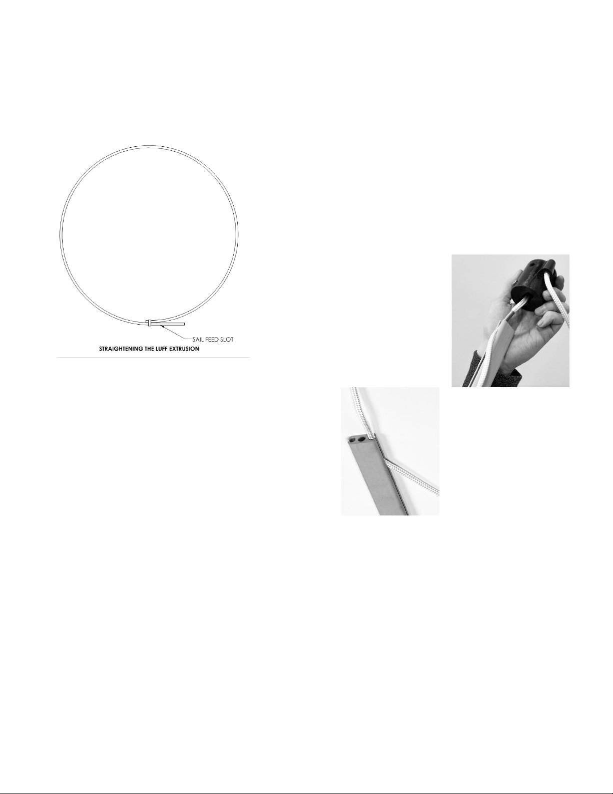
8. Pass the swage-end of
the headstay down
through the halyard top
fitting and the luff.
Using locking pliers,
hold the luff above the
threaded pin and screw
on the turnbuckle body.
9. Using your T-bolt, add additional washers to reduce the
clearance between the T-bolt and the bottom of the cup.
Note: T-bolt fittings are preferred, “i-bolt” fittings may not fit
10. Add the anti-rotation strap to the T-bolt and washers.
11. Place the T-bolt and the anti-rotation strap through the
bottom of the cup, then add the bearing (plastic or ball-
bearing) to the T-bolt on the inside of the cup.
12. Align the holes of the cup with the ant-rotation strap
depending on the set-up of your furling line and screw the
assembly together.
13. Slide the furling drum/spool onto the luff, lining up the
sail-feed slot with the tack anchor shackle. Ensure that the
thrust washer stays inside the bottom opening of the spool.
14. If mast is up, take the T-bolt assembly and screw into the
turnbuckle body, adjust to the correct length. Ensure that all
cotter pins are replaced in the turnbuckle.
15. Lower the spool/drum over the bearing then raise the luff
and insert the luff support pin with the cotter ring into the
spool.
Note:DO NOT DRILL A HOLE THROUGH THE LUFF EXTRUSION
The luff rests on top of the luff support pin, not through it.
16. If mast is down, step the mast and attach headstay.
17. Adjust the backstay to normal
tension. If headstay needs adjusting,
remove the luff support pin and raise
the spool to adjust, afterwards
reinserting the luff support pin.
18. Use a furling line (not included) to
go through the opening in the cup
and up through the hole on the top
flange of the spool, tie a knot to
secure the line in place.
19. Manually rotate the spool/drum 20 times to wrap the
furling line around the spool.
20. Position the first fairlead or block (not included) so the
furling line exits the middle of the cup to avoid any friction.
To adjust where the opening of the cup is pointing, repeat
step 14 to get the correct alignment.
21. Place a cleat (not included) near the cockpit in an easily
accessible spot to tie off the furling line.
22. To trim the halyard for sails that are full hoist, ensure the
messenger line is attached then pull the halyard so the end
with the ferrule (FF4) or traveler (FF6) reaches the top of the
forestay at the halyard top fitting. Make your cut so the
halyard line will be just below the sail
feed slot.
23. For sails that are not full hoist,
estimate the distance between the
head of the sail and the top of the
forestay when the sail is raised.
(A in diagram)
24. Ensure the messenger line is
attached then pull the halyard so the
end with the ferrule (FF4) or traveler
(FF6) reaches the top of the forestay at
the halyard top fitting. Make your cut
so the halyard line will be just below
the sail feed slot, then add your
estimated measurement to this length,
now you can make your cut.
The following is for FF4 systems, FF6 systems follow 25.B)
25. A) For the FF4 line halyard, cut the end with scissors and
melt the end to prevent fraying.
A

The following is for FF6 systems, FF4 systems follow 25. A)
25. B) For the FF6 wire halyard, apply the Nicopress double
oval sleeve then form a loop and insert the thimble in the
middle. Crimp down on the Nicopress using a crimping tool.
26. Attach the halyard to the head of the sail. The FF6 will be
attached with the supplied halyard shackle, a shackle is
optional for the FF4.
27. Feed the luff of the sail into the sail-feed slot while
hoisting the sail by pulling on the messenger line which is
attached to the de-cored end of the halyard (step 6).
28. Remove the messenger line once the sail is fully hoisted
and tie off the halyard on the anchor shackle on the spool.
Note: Always remember to reattach the messenger line when
lowering your sail.
29. Tension the sail by tightening the tack tension line to the
second shackle on the spool and hoisting the sail tight by
pulling on the halyard, using a winch shouldn’t be required.
30. Furl in the sail by pulling on the furling line and keeping
tension on the jib sheet.
SAILMAKER INSTRUCTIONS
Sails require #6 luff tape to be compatible with all CDI furlers
Webbing at the head and tack of the sail is recommended
instead of metal grommets for smooth furling but is not
required.
RIGGING INSTRUCTIONS
The CDI flexible furler system cannot be mounted above the
turnbuckle as it can cause it to unscrew and dismast. If more
clearance is required, it’s recommended to add link plates.
The FF4 and FF6 systems are compatible with 1/4”, 5/16”,
3/8” and 7/16” turnbuckles with a threaded swage-end and a
T-bolt toggle.
Note: Most Navtec turnbuckles do not work and are not
recommended as they’re often too large to fit inside the drum
T-bolt fittings are preferred, “i-bolt” fittings may not fit
Cotter pins should be used to lock the turnbuckle, not locknuts
as these can unscrew and cause dismasting.
Toggles are required at the bottom of the headstay, any
secure fitting at the top of the forestay will work but a toggle
is also recommended.
NOTES ABOUT SAILING
The tension on the luff doesn’t need to be high and should
only be tight enough to removes any creases in the sail.
When sailing reefed, the jib leads should be moved forward
to maintain proper sail shape and avoid the furler from rising
off the bearing.
To furl your sail, always keep tension on your sail’s jib sheet
while reefing the furling line.
NOTES ABOUT TRAILERING
When trailering, strap the furler to the mast in a horizontal
position and support the end with the hardware by using a
support extension ie. 2x4 or PVC tube
Keep the extrusion as straight as possible, do not let either
end sag or twist.
MAINTENANCE
The only maintenance required is to rinse the furler system
including the ball-bearing assembly if applicable, with fresh
water 1-2 times per year. Clear out any salt or dirt that may
have accumulated.
Note: Lubricants are not required but Teflon sprays or dry
lubricants are acceptable if needed.
STORING YOUR FURLER
Storage is best accomplished by strapping the furler to the
mast in a horizontal position and supporting the end with the
hardware by using a support ie. 2x4 or PVC tube
When storing, avoid making sharp bends in the extrusion.
This can become permanent after a period of time and is not
covered under warranty.
It is not necessary to remove or recoil your extrusion, doing
this over long periods of time can become permanent and is
not recommended as the furler ages.
Avoid exposing the furler in temperatures above 140F/60C

WARRANTY
The CDI Flexible Furler comes with a 10-year limited warranty
In order for the warranty to be valid, you must be the original
owner of the system and have proof of purchase which
clearly indicates the date of purchase.
If any part becomes non-functional during this time, CDI will
repair or replace it free of charge, not including shipping.
Note: this warranty does not cover damage incurred from
weather, trailering or transporting, collisions at sea, improper
storage, improper uncoiling or straightening of the luff
including using weights or heat guns, etc.
NOTES:
21 SOUTH LANDING DR –OAK BLUFF, CANADA
P: 844-379-2407 | F: 204-896-6969
2022
This manual suits for next models
1
Table of contents
Other CDI Marine Equipment manuals
Popular Marine Equipment manuals by other brands

GUIDANCE MARINE
GUIDANCE MARINE RadaScan View Installer's guide

Dometic
Dometic Optimus EPS Installation and user manual

Raymarine
Raymarine SPX-5 Installation & setup guide

Wet Sounds
Wet Sounds WS-MC2 owner's manual

AC MARINE
AC MARINE KUM400 Series installation guide

Quick
Quick MC2 Series Installation and use manual