Metasys PA400 Reference manual

Fire Initiating Devices and Notification Appliances Technical Manual 408
Notification Appliances Section
Technical Bulletin
Issue Date 1095
© 1995 Johnson Controls, Inc. 1
Code No. LIT-408230
Introduction Page 3
●
General Description 3
Installation Procedures 7
●
General Information 7
●
Mounting 7
●
Wiring Installation Guidelines 9
●
Limitations 10
PA400 Electronic Mini-Sounders and
PS12/24 Series Optional Strobes

2 Notification Appliances—PA400 Electronic Mini-Sounders and PS12/24 Series Optional Strobes
Notification Appliances—PA400 Electronic Mini-Sounders and PS12/24 Series Optional Strobes 3
Introduction
This document contains important information about installing and
operating the PA400 electronic mini-sounders and the PS12/24 series
optional strobes. These electronic mini-sounders and optional strobes are
manufactured by System Sensor for use with Johnson Controls systems.
If you install these electronic mini-sounders and optional strobes for
someone else to use, you must leave a copy of this document with the
user.
These instructions apply to Johnson Controls electronic mini-sounders and
optional strobes for mounting and wiring. Follow only those instructions
that apply to the model you are installing.
Before you install any electronic mini-sounders and optional strobes, read
and be familiar with:
●applicable NFPA Standards, local codes, and the requirements of the
authority having jurisdiction.
●or, for non-United States installations, applicable codes and standards
specific to the country and locality of installation.
Failure to follow these directions may result in failure of the device to
report an alarm or trouble condition. Johnson Controls is not responsible
for devices that have been improperly installed, tested, or maintained by
others.
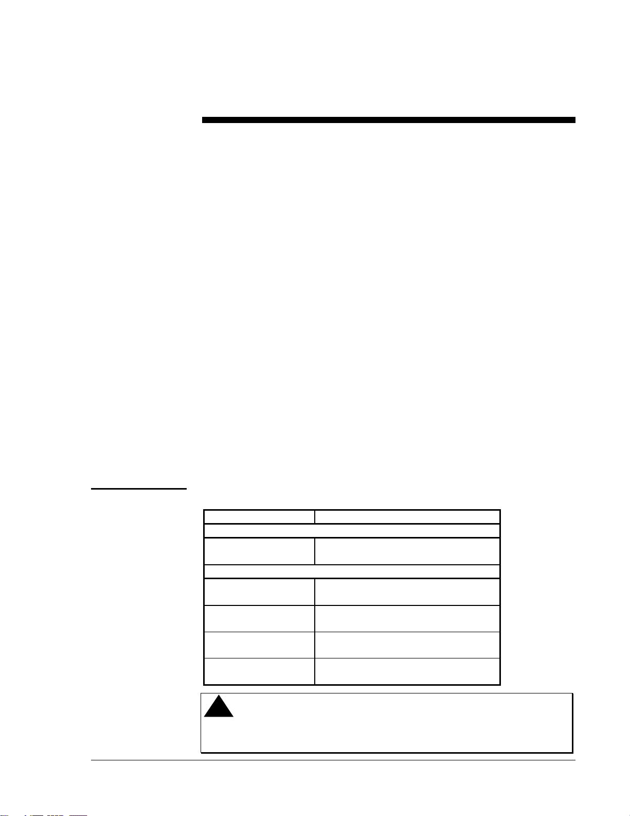
Table 1: Models
Model Number Description
Sounders
PA400R
PA400B 12 or 24 VDC, Red
12 or 24 VDC, Beige
Strobes
PS12LO
PS12LOB 12 VDC, 1.5 Candela, Red
12 VDC, 1.5 Candela, Beige
PS12M
PS12MB 12 VDC, 15 Candela, Red
12 VDC, 15 Candela, Beige
PS24LO
PS24LOB 24 VDC, 1.5 Candela, Red
24 VDC, 1.5 Candela, Beige
PS24M
PS24MB 24 VDC, 15 Candela, Red
24 VDC, 15 Candela, Beige
!
CAUTION: Equipment hazard. Do not use in potentially
explosive atmospheres. Do not leave unused
wires exposed.
General
Description
4 Notification Appliances—PA400 Electronic Mini-Sounders and PS12/24 Series Optional Strobes
The PA400B (beige) and PA400R (red) Piezo Alert electronic sounder and
optional models PS12 and PS 24 supplementary signal strobes are
intended to be connected to the alarm Notification Appliance Circuit
(NAC) of a UL Listed 12 or 24 Volts Direct Current (VDC) Fire Alarm
Control Panel (FACP).
The sounders and strobes operate on full-wave rectified, filtered, regulated
DC voltages as well as unfiltered, unregulated DC from power supplies
UL Listed for fire alarm applications.
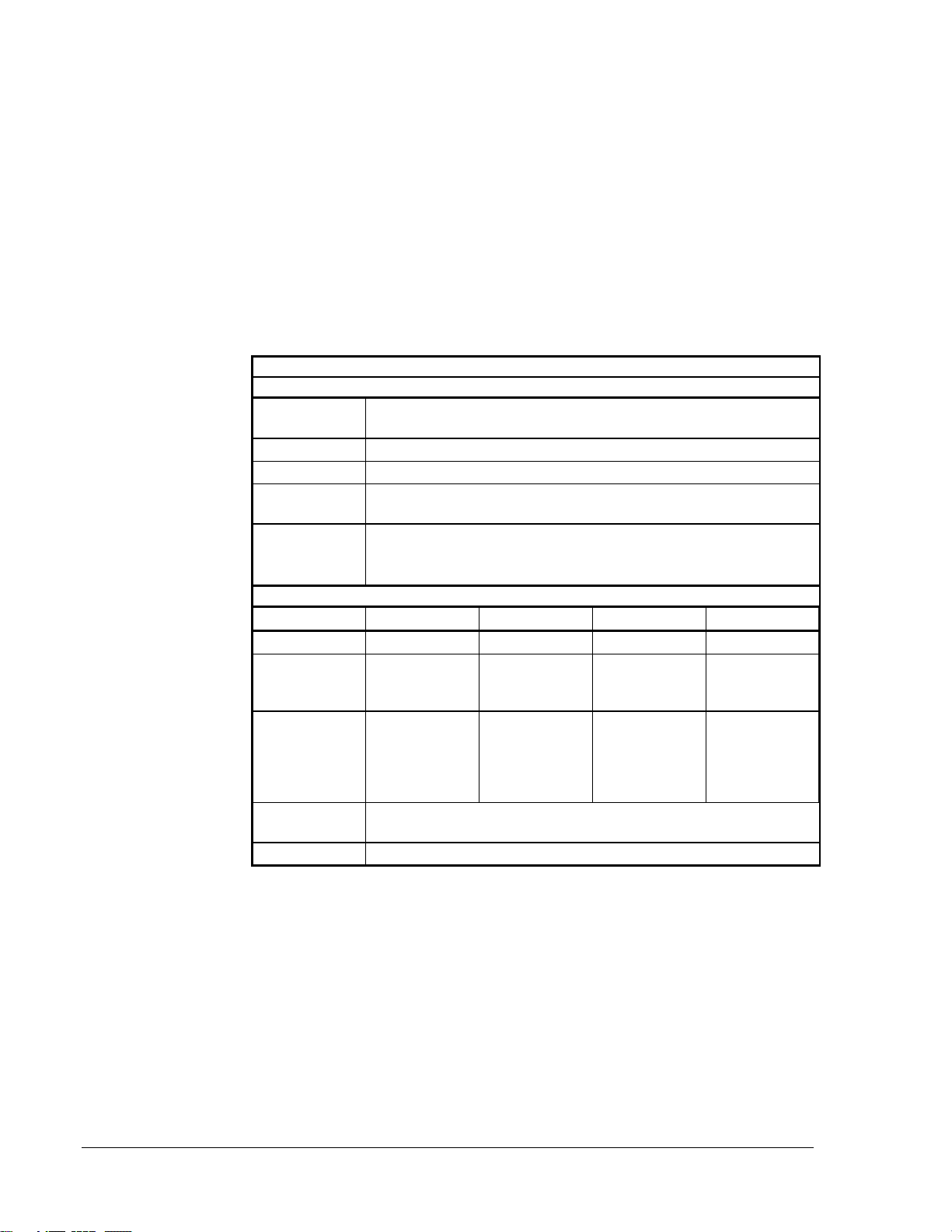
Table 2: Specifications Summary
Specifications
PA400 Sounder
Operating
Voltage 9.6 VDC (absolute min.) to 33 VDC (absolute max.)
Current Drain 12 mA at 12 volts
15 mA at 24 volts
Temperature
Range 14 to 140°F (-10 to 60°C); 90% maximum RH PA400
32 to 120°F (0 to 49°C) ; 90% maximum RH with strobe added
Sound Output Greater than 90 dBA measured in anechoic room at 10 feet, 24 volts.
For other voltages, see Figure 1.
82 dBA minimum measured in UL reverberant room (75 dBA with strobe)
PS 12/24 Strobe
Model PS12LO PS12M PS24LO PS24M
Panel Voltage 12 VDC 12 VDC 22.5 - 30 VDC 22.5 - 30 VDC
Max. Current
Drain @ Listed
Panel Voltage
50 mA 180 mA 25 mA 75 mA
Min. Light
Output @
100% Viewing
Angle
(See Figure 2)
1.5 candela 15 candela 1.5 candela 15 candela
Temperature
Range 32 to 120°F (0 to 49°C); 90% maximum RH
Flash Rate 1/3 to 2 Hz
Note: The strobe cannot operate form coded power supplies, which
produce interrupted power. The strobe must have an uninterrupted
source of power in order to operate correctly.
Model PA400

Notification Appliances—PA400 Electronic Mini-Sounders and PS12/24 Series Optional Strobes 5
strbgrh3
14 16
18
20
2210 12
92
91
90
89
87
86
88
dBA Output
Voltage
Figure 1: Voltages
strobe1
75%
80% 60%
75%
60%60%
100% 100%
(
REF
)
100%
Figure 2: Minimum Light Output in Percent of Rated Output
• Under no circumstances can the PS24 voltage exceed 33 VDC or be
less than 18 VDC.
6 Notification Appliances—PA400 Electronic Mini-Sounders and PS12/24 Series Optional Strobes
• Under no circumstances can the PS12 voltage exceed 15 VDC or be
less than 9.6 VDC.
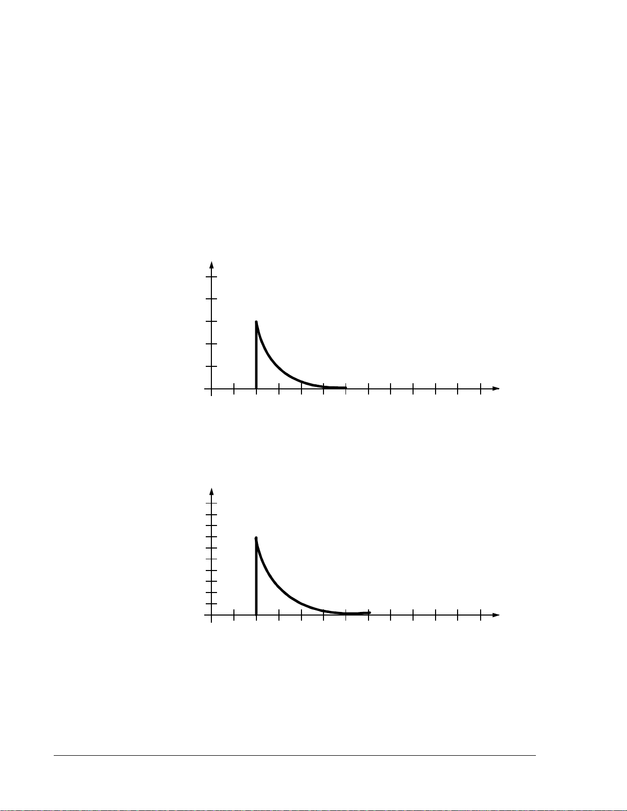
To calculate battery requirements, use current values shown in Table 2.
However, note that there is an inrush current associated with strobe power-
up. The information in Figures 3 and 4 is useful when selecting fuse
values.
The 12V strobe inrush current typically peaks at 3A and drops to nominal
in 600 microseconds (Figure 3). In a 24V strobe, the inrush current
typically peaks at 7.0 amperes and drops to nominal in 800 microseconds
(Figure 4).
1A/div
200uS/div
strbgrh1
Figure 3: 12 Volt Strobe Inrush Current
1A/div
200uS/div
strbgrh2
Figure 4: 24 Volt Strobe Inrush Current
Notification Appliances—PA400 Electronic Mini-Sounders and PS12/24 Series Optional Strobes 7
Installation Procedures
This section contains installation information for the PA400 electric
mini-sounders and PS12/24 series optional strobes. Instructions are given
for mounting the sounders and strobes, and basic wiring information is
provided.
1. The PA400 is intended for mounting to a standard 2-1/2 inch deep
single gang box which allows sufficient clearance for conduit
entrance.
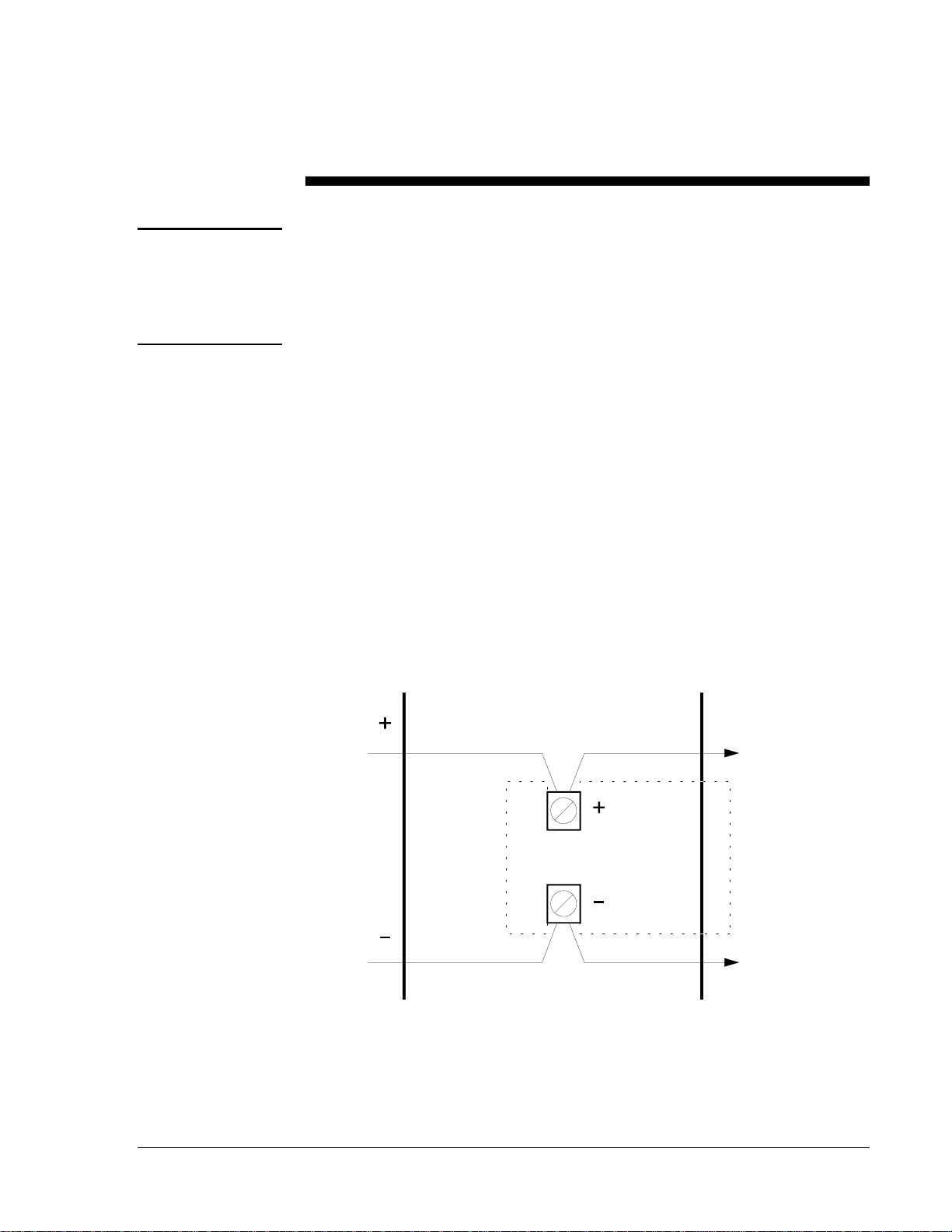
2. The PA400 is compatible with Direct Current (DC) line supervision.
The piezo alert is polarized and has terminals marked with polarity.
3. Apply positive supply voltage to the (+) terminal and negative supply
voltage to the (–) terminal (Figure 5).
4. Mount the appliance to the electrical outlet box using the two
mounting screws supplied.
5. Field repair of the PA400 should not be attempted. Return to factory
for repair or replacement.
To End ofLine
(
EOL
)
or
Next Device
highint5
From
Control Panel
or Previous
Device
Figure 5: Mounting the PA400 Sounders
Note: Polarity shown with the control panel in alarm. Panel polarity
reversed in supervisory condition (Figure 5).
General
Information
Mounting
PA400 Sounders

8 Notification Appliances—PA400 Electronic Mini-Sounders and PS12/24 Series Optional Strobes
To interconnect the PS12 and PS24 optional strobes to the PA400
sounder:
1. Remove the two mounting screws from the sounder.
2. Use a small screwdriver to punch out the skinned-over areas as
indicated in Figure 6.
3. Install the adapter plate on top of the sounder, and screw the
combined sounder and adapter plate to the electrical outlet box.
Make sure field wiring terminals are oriented in the upward position
when mounted in the outlet box.
4. Slide the strobe directly into the slots in the plates.
The positive solder lug may be colored red or marked with a
plus sign (+). This lug must be in the slot closest to the field wiring
terminals.
5. Grasp the catch area on each end of the strobe, and squeeze while
applying inward force.
6. Make sure the strobe catches fully engage the slots in the adapter
plate.
7. Make sure the interface between the strobe and adapter plate is free of
gaps.
Figure 6: Mounting the PS12 or PS24 Strobe
PS12 or
PS24 Strobes
minihrn

Notification Appliances—PA400 Electronic Mini-Sounders and PS12/24 Series Optional Strobes 9
The wiring must be in compliance with all applicable codes, and must not
be of such length or wire size that would cause the appliance to operate
outside of its published specifications.
Do not loop the NAC wires under terminal screws. Wires connecting the
device to the panel must be broken at the device screw terminal in order to
maintain electrical supervision.
Wiring
Installation
Guidelines

10 Notification Appliances—PA400 Electronic Mini-Sounders and PS12/24 Series Optional Strobes
The appliances must be tested after installation. Refer to the control panel
manufacturer’s test procedure. This sounder and signal strobes are
designed for installation in accordance with the NFPA Standard 72-
National Fire Alarm Code, or equivalent codes and standards applicable to
the country of installation.
●Sounder and signal strobes are designed to provide fire and security
hazard warnings.
●The strobe is for supplementary signaling use only.
●The sounder or sounder/strobe combination will not work without
power. The sounder or sounder/strobe gets its power from the fire or
security panel monitoring the alarm system. If power is cut off for
any reason, the sounder or sounder/strobe combination will not
provide the desired audible or visual warning.
●The sounder may not be heard. However, the sounder may not alert a
sound sleeper, one who has recently used drugs, or one who has been
drinking alcoholic beverages. The sounder may not be heard if it is
placed in an area which is isolated by a closed door, if it is located on
a different floor from the person in hazard, or if placed too far away to
be heard over the ambient noise such as traffic, air conditioners,
machinery, or music appliances that may prevent alert persons from
hearing the alarm. The sounder may not be heard by persons who are
hearing impaired.
●The signal strobe may not be seen. The electronic visual warning
signal meets or exceeds current Underwriters Laboratories
Standard 1638. The visual warning signal is suitable for direct
viewing, and it must be installed within an area where it can be seen
by building occupants. The strobe must not be installed in direct
sunlight or in areas of high light intensity (over 60 foot-candles)
where the visual flash might be disregarded or not seen. The strobe
may not be seen by the visually impaired.
●The signal strobe may cause seizures. Individuals who have a
positive photic response to visual stimuli with seizures, such as
epileptics, should avoid prolonged exposure to environments in which
strobe signals, including this strobe, are activated.
Limitations

Notification Appliances—PA400 Electronic Mini-Sounders and PS12/24 Series Optional Strobes 11
Notes

12 Notification Appliances—PA400 Electronic Mini-Sounders and PS12/24 Series Optional Strobes
Notes
Controls Group FAN 408
507 E. Michigan Street Fire Initiating Devices and Notification Appliances Technical Manual
P.O. Box 423 Printed in U.S.A.
Milwaukee, WI 53201
This manual suits for next models
2
Table of contents
Other Metasys Marine Equipment manuals


