Moog G128-809 Supplement
Power Supply 24VDC – 2A
G128-809
Application Notes
1 Scope
These application notes are a guide to applying the G128-809
Power Supply. They tell you how to install and connect the
G128-809.
2 Description
The G128-809 provides a compact, efficient and reliable power
supply where a regulated fixed 24VDC output is required for
other DIN modules. A wide range of commonly encountered
input supplies can be used. The DC output is isolated from the
input supply. The DC output has good regulation and low
noise, with a minimum 2A continuous capacity.
The G128-809 is idle and short circuit protected. Multiple
G128-809’s can be connected to provide redundant operation.
For a more detailed description see data sheet
G128-809.
3 Installation
3.1 Placement
A horizontal DIN rail, mounted on the vertical rear surface of
an industrial steel enclosure, is the intended method of
mounting. The rail release clip of the G128-809 should face
down, so the front panel and terminal identifications are
readable and so the internal electronics receive a cooling
airflow. An important consideration for the placement of the
module is electro magnetic interference (EMI) from other
equipment in the enclosure. For instance, VF and AC servo
drives can produce high levels of EMI. Always check the EMC
compliance of other equipment before placing the G128-809
close by.
3.2 Cooling
Vents in the top and bottom sides of the G128-809 case
provide cooling for the electronics inside. These vents must be
left clear. A spacing distance of a minimum of 100mm should
be allowed above and below the cooling vents for placement
of other modules. It is important to ensure that equipment
below does not produce hot exhaust air that heats up the
G128-809.
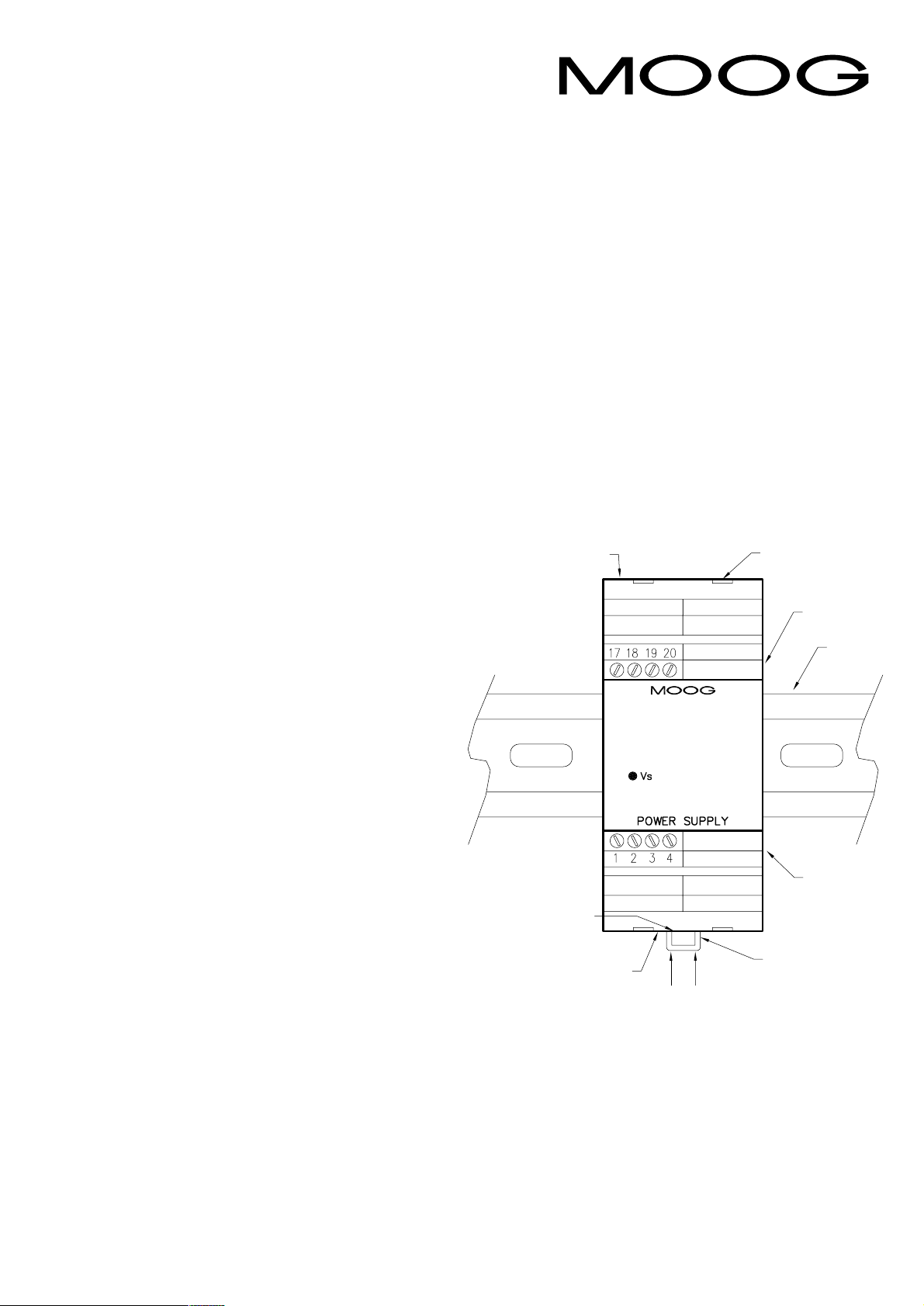
Screw
terminals
17 - 20
Cover release tabs (x4)
Top vents
DIN rail
Screw
terminals
1 - 4
ottom
vents Cooling
airflow
DIN rail
release
clip
Cover release tab
3.3 Wiring
The use of crimp “boot lace ferrules”is recommended for the
screw terminals. The input supply cable should be rated for
the supply voltage used at an operating temperature of
75°C.
Do not work on the module while connected to the input
supply. There are no internal adjustments in the G128-809.

Alternative Wiring
3.4 EMC
The G128-809 emits radiation below the level called for in its
CE mark test.
Immunity from external interfering radiation is dependent on
careful wiring techniques. The accepted method is to use
screened cables for all connections and to radially terminate
the cable screens, in an appropriate grounded cable gland, at
the point of entry into the industrial steel enclosure. Exposed
wires should be kept to a minimum length. Connect the
screens at both ends of the cable to chassis ground.
3.5 Power supply
The G128-809 can use either an AC or DC input supply.
It must be possible to switch off the supply to the G128-809
using a suitable switch or disconnecting device. A suitable fuse
must be fitted where DC supply is used.
•The AC supply can be in the range 90 to 260VAC,
45 to 65Hz.
•The DC supply can be in the range 90 to 350VDC.
5 Front panel
Caution: Never carry out any work
on the G128-809 when power is present.
Danger to life.
4 Set-up
4.1 Input
The AC or DC supply connection is made using the screw
terminals shown in the block wiring diagram. Wiring must be
carried out properly to ensure protection against electric
shocks.
4.2 Output
The +24V, 0V and DC OK signal is available on the screw
terminals. The DC OK output provides 24V @ 20mA while
supply is operating correctly. Refer to block diagram.
4.3 Short Circuit/Overload
The G128-809 is short circuit protected and idle proof. In the
event of an error the DC output is limited to 33V +/–5%.
4.4 Redundant Operation
Multiple G128-809’s can be connected together to form a
redundant power supply.
Preferred Wiring

Maximum power loss: 10W at nominal load.
Front Panel Indicator: Vs: Green power LED.
Mounting: DIN rail.
Protection type: IP 20.
Temperature: 0 to +40°C.
Dimensions: 100W x 108H x 45D.
Weight: 250g.
Approvals: CE mark: EN50081.2 emission.
EN61000-6-2 immunity.
7 Block Wiring Diagram
8 Specifications
Supply: 90 to 260VAC, 45 to 65Hz.
90 to 350VDC.
Inrush current: < 35A for < 3mS @ 25°C.
Isolation: 4kV.
Mains buffering: > 20mS @ 120VAC,
> 100mS @ 230VAC.
Output – voltage: 24VDC fixed –0% / +3%.
–current: 4A max. @ 230VDC, Tamb ≤30°C.
2A max. @ all input voltages,
Tamb ≤60°C.
Startup delay: < 100mS.
Ripple: 100mV p-p typical at nominal load.
Load regulation: < 1% static for 10% to 90% load
change.
< 3% dynamic for 10% to 90%
load change.
6 Withdrawing the circuit card from
its case
Caution: When the device is
opened, a dangerous voltage may
remain in the electrolytic capacitors for
up to two minutes after shutdown.
There are no internal user adjustments in the G128-809.
If access to the circuit is required, the circuit card needs to be
withdrawn from its case. To do this, push one tab in with a
pen or screwdriver while gently pulling on the top cover on
that side. The cover will release approximately one mm. Repeat
on the other side and withdraw the cover and circuit card.
Note 1: Connect cable screen to enclosure cable gland or chassis ground

C70129
Internet Data
For a detailed Data Sheet and the latest version of this
Application Note please refer to the Moog website
www.moog.com/dinmodules
Industrial Controls Division. Moog Inc., East Aurora, NY 14052-0018. Telephone: 716/652-3000. Fax: 716/655-1803. Toll Free 1-800-272-MOOG.
Moog GmbH. Germany. Telephone: 07031-622-0. Fax: 07031-622-100.
Moog Sarl. France. Telephone: 01 45 60 70 00. Fax: 01 45 60 70 01.
Moog Australia Pty. Ltd. Telephone: 03 9561 6044. Fax: 03 9562 0246.
Moog pursues a policy of continuous development and reserves the right to alter designs and specifications without prior notice. Information contained herein is for guidance only and does not form part of a contract.
Australia: Melbourne, Sydney, Brisbane Austria: Vienna Brazil: S~
ao Paulo Denmark: Birkerød England: Tewkesbury Finland: Espoo France: Rungis Germany: Böblingen, Dusseldorf Hong Kong: Shatin India: Bangalore
Ireland: Ringaskiddy Italy: Malnate (VA) Japan: Hiratsuka Korea: Kwangju-Kun Philippines: Baguio City Singapore: Singapore Sweden: Askim USA: East Aurora (NY)
This page has been left blank intentionally.
Other Moog Power Supply manuals


