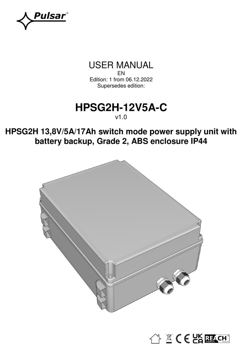
Moog G396-026 User manual

moog
Power Supply Unit
with sinusoidal mains feedback
Programmable
Multi-Axis
Servo Drive
Power Supply Unit (PSU)
Sizes 5 and 6A
Operation Manual

Size Size 5 Size 6A
Device G396-026
G396-050
G396-075
G396-110
Picture
Programmable Multi-Axis
Servo Drive Power Supply Unit (PSU)
Operation Manual
ID no.:CA97556-001, Rev. 2.0
Date: 04/2015
Applicable as from firmware version: V220.13-01
The German version is the original of this Operation Manual.
MSD Servo Drive high-performance drives
The modular design of Multi-Axis Servo Drive ensures optimal integration into the ma-
chine process. Whether in high-speed fieldbus communication with the central multi-axis
machine controller or with distributed programmable Motion Control intelligence in the
servo drive, the Multi-Axis Servo Drive is a master of both.
We reserve the right to make technical changes.
The contents of our documentation have been compiled with greatest care and in
compliance with our present status of information.
Nevertheless we would like to point out that this document cannot always be updated
parallel to the technical further development of our products.
Information and specifications may be changed at any time. For information on the
latest version please refer to drives-support@moog.com.
2
Programmable Multi-Axis Servo Drive Power Supply Unit Operation Manual
ID no.:CA97556-001 Date:03/2015
moog

Programmable Multi-Axis Servo Drive Power Supply Unit Operation Manual
ID no.:CA97556-001 Date:03/2015
moog 3
Guide through this document
Guide through this document
Dear user,
We are happy that you have made a decision in favour of a product from Moog. In order
to be able to start using your new device quickly and without problems, we ask you
kindly to read this Operation Manual thoroughly beforehand.
This Operation Manual will enable you to install and commission the Power Supply Unit very
quickly and easily.
Simply follow the step-by-step tables in the various chapters. And away you go!
Documentation system for the Programmable Multi-Axis Servo Drive
System (MSD)
Document Contents Description
Programmable Multi-Axis
Servo Drive Power Supply Unit
(PSU)
Operation Manuall
Mechanical installation, Electrical
installation, Safety, Specification Hardware and software
Programmable Multi-Axis
Servo Drive Operation Manual
Mechanical installation, Electrical
installation, Safety, Specification Hardware and software
MSD Servo Drive Device Help Description of base software Software
CANopen/EtherCAT User Manual
Description and parameter set-
ting of the MSD Servo Drive on
the CANopen/EtherCAT fieldbus
system
Hardware and software of the
fieldbus option
SERCOS User Manual
Description and parameter set-
ting of the MSD Servo Drive on
the SERCOS II fieldbus system
Hardware and software of the
fieldbus option
PROFIBUS / PROFINET
User Manual
Description and parameter
setting of the MSD Servo Drive
on the PROFIBUS / PROFINET
fieldbus system
Hardware and software of the
fieldbus option
1.
2.
1 Safety
2Overview
3Mechanical installation
4 Electrical installation
5 Commissioning
6 Diagnostics
A Appendix
Index
Figure 0.1 Guide through this document

Programmable Multi-Axis Servo Drive Power Supply Unit Operation Manual
ID no.:CA97556-001 Date:03/2015
moog 4
Guide through this document
Production data
On rating plates of the Power Supply Unit you will find the serial number, from which
you can identify the date of manufacture based on the following key. You will find
details of the rating plate’s location on the Power Supply Unit starting on page13.
Model:: G396-040-000-002
In: 230 V AC 3ph, 50/60 Hz
4,0 A
0-230 V AC 3ph, 0-400 Hz
3,0 A
Out:
ID: YYCWxxxxx
Year of production
Week of production
MOOG
D-71034 Böblingen
www .moog.com/industrial
Made in Germany
S/N:D116605 Rev. A
Figure 0.3 Hardware rating plate – Power Supply Unit
Supply package
The supply package includes:
yPower Supply Unit (PSU)
yReady made-up DC link cables for size 5 and size 6A
yProduct DVD
Order code
The order designation indicates the design variant of the Power Supply Unit supplied
to you. For details on the order code refer to the Programmable Multi-Axis Servo Drive
System (MSD) Ordering Catalog.
G396 - - -
Rated power
Option 1 (Communication)
For future use
Variants
Housing/cooling method
Option 4 (Function package)
Figure 0.2 Order code – Power Supply Unit

Programmable Multi-Axis Servo Drive Power Supply Unit Operation Manual
ID no.:CA97556-001 Date:03/2015
moog 5
Guide through this document
Required mains connection set
The mains connection set is required to ensure compliance with the intended use of the
Power Supply Unit. The supply package includes:
yMains filter
yInput choke with membrane capacitor
yStep-up choke
yShields and clamps
Pictograms
To provide clear guidance, this Operation Manual uses pictograms. Their meanings are
set out in the following table. The pictograms always have the same meanings, even
where they are placed without text, such as next to a connection diagram.
Warning symbols (see also section1.1, p.9)
!ATTENTION!
Misoperation may result in damage to the drive or malfunctions.
DANGER FROM ELECTRICAL TENSION!
Improper behaviour may endanger human life.
Hints & Tips
NOTE:
Useful information or reference to other documents.
1.
STEP:
Action in a sequence of multiple actions.

Programmable Multi-Axis Servo Drive Power Supply Unit Operation Manual
ID no.:CA97556-001 Date:03/2015
moog 6
Table of contents
3.2 Effective EMC installation..........................................................................................25
3.2.1 Cable type .................................................................................................25
3.2.2 Cable laying...............................................................................................26
3.2.3 Earthing.....................................................................................................26
3.2.4 Shielding....................................................................................................27
3.3 Overview of connections...........................................................................................28
3.3.1 Layout, size 5 (G396-026 and G396-050)..................................................28
3.3.2 Layout, size 6A (G396-075 and G396-110) ................................................28
3.3.3 Overview of connections, size 5 and size 6A..............................................29
3.3.4 Connection diagram, size 5........................................................................30
3.3.5 Connection diagram, size 6A .....................................................................32
3.4 Connection of PE conductors....................................................................................33
3.4.1 PE conductor (X11)Power Supply Unit size 5..............................................33
3.4.2 PE conductor (X11)Power Supply Unit size 6A ...........................................34
3.4.3 PE conductor components .........................................................................35
3.5 Electrical isolation method ........................................................................................35
3.6 Connection of supply voltages ..................................................................................36
3.6.1 Control supply 24VDC (X9, X10) for size 5 and size 6A ............................36
3.6.2 Precharge and mains synchronisation (X21) for size 5 and size 6A .............37
3.6.3 Mains connection 400/480VAC (X12) for size 5 and Size6A....................38
3.7 DC power supply connection ....................................................................................40
3.7.1 DC power supply connection(X11) size 5....................................................41
3.7.2 DC power supply connection (X11) size 6A ................................................42
3.8 Control connections (X4)...........................................................................................44
3.8.1 Specification of control connections ..........................................................44
3.8.2 Standard terminal assignment....................................................................45
3.9 Functions of the digital inputs...................................................................................46
3.10 Functions of the digital outputs ................................................................................46
Table of contents
1 Safety.............................................................................................9
1.1 Measures for your safety .............................................................................................9
1.1.1 Read the Operation Manual first!.................................................................9
1.1.2 Warning symbols used...............................................................................10
1.2 Intended use .............................................................................................................10
1.3 Usage contrary to intended use.................................................................................10
1.4 Responsibility ............................................................................................................ 11
2 Mechanical installation.................................................................. 13
2.1 Notes for mechanical installation............................................................................... 13
2.2 Effective EMC installation..........................................................................................14
2.2.1 General notes ............................................................................................14
2.2.2 Cabinet design...........................................................................................14
2.3 Power Supply Unit installation Air-cooled housing .................................................... 17
2.3.1 Dimensions, air-cooled housing .................................................................18
2.4 Power Supply Unit installation Liquid-cooled housing ...............................................19
2.4.1 Dimensions, liquid-cooled housing ............................................................20
2.5 Cooling circuit connection.........................................................................................21
2.6 Step-up choke installation.........................................................................................22
2.6.1 Dimensions ................................................................................................22
2.7 Installation of input choke with membrane capacitor................................................23
2.7.1 Dimensions ................................................................................................23
2.8 Mains filter installation ..............................................................................................24
2.8.1 Dimensions ................................................................................................24
3 Electrical installation .....................................................................25
3.1 Before you start ........................................................................................................25

Programmable Multi-Axis Servo Drive Power Supply Unit Operation Manual
ID no.:CA97556-001 Date:03/2015
moog 7
Table of contents
4.4.2 Display .......................................................................................................59
4.4.3 Parameters menu (PA)................................................................................60
4.4.4 Ethernet IP address menu (IP).....................................................................61
4.4.5 Fieldbus address menu (Fb)........................................................................62
4.4.6 Firmware update with MMC card ..............................................................63
5 Diagnostics...................................................................................64
5.1 Device states .............................................................................................................64
5.1.1 Error ..........................................................................................................64
5.2 Error list ....................................................................................................................65
5.3 Helpline/Service ........................................................................................................65
A Appendix......................................................................................66
A.1 Technical data of Power Supply Unit .........................................................................66
A.2 Current consumption of control supply .....................................................................69
A.3 Ready made-up cables ..............................................................................................69
A.4 Hydrological data of liquid cooling............................................................................70
A.5 Dynamic temperature monitoring .............................................................................70
A.6 Ambient conditions...................................................................................................70
A.7 Technical data of step-up choke................................................................................72
A.8 Technical data of input choke....................................................................................72
A.9 Technical data of mains filter.....................................................................................73
A.10 Technical data of mains fuse .....................................................................................73
A.11 Technical data of mains contactor .............................................................................73
A.12 Technical data of circuit-breaker................................................................................73
A.13 Measures to attain UL approbation (UL508C) size 5.................................................74
A.14 Measures to attain UL approbation (UL508C) size 6A .............................................. 74
B Overview......................................................................................75
Index ...................................................................................................78
3.11 Specification of USB port (X2)...................................................................................47
3.12 Specification of Ethernet port (X3)............................................................................47
3.13 Option 1 ...................................................................................................................47
3.14 Braking resistor (X12/RB) ...........................................................................................47
3.14.1 Connection of the external braking resistor ...............................................47
3.15 Overview of step-up choke connections....................................................................48
3.16 Overview of input choke connections .......................................................................49
3.17 Overview of mains filter connections.........................................................................50
4 Commissioning............................................................................. 51
4.1 Notes for operation................................................................................................... 51
4.2 Initial commissioning (actuation via terminals)........................................................... 51
4.2.1 System requirements .................................................................................52
4.2.2 Wiring of components ...............................................................................52
4.2.3 Switching on control voltage (24 VDC) ......................................................53
4.2.4 Communication with the Moog DriveADministrAtor 5 .................................53
4.2.5 Setting the mains voltage and frequency of the supply system ..................54
4.2.6 Automatic identification of DC link capacity and equivalent time
constant of current control ........................................................................55
4.2.7 Setting DC link capacity.............................................................................55
4.2.8 Setting DC link voltage ..............................................................................56
4.2.9 Programming monitoring of the braking resistor........................................56
4.2.10 Connecting the mains supply voltage ........................................................57
4.2.11 Activating closed-loop control ...................................................................57
4.3 Diagnostics ...............................................................................................................57
4.3.1 Faults and warnings in Moog DriveADministr Ator 5 .....................................57
4.4 Integrated operator control unit and MMC card .......................................................58
4.4.1 Functions of buttons T1 and T2 .................................................................59

Programmable Multi-Axis Servo Drive Power Supply Unit Operation Manual
ID no.:CA97556-001 Date:03/2015
moog 8
Table of contents

Programmable Multi-Axis Servo Drive Power Supply Unit Operation Manual
ID no.:CA97556-001 Date:03/2015
moog 9
Safety
1 Safety
1.1 Measures for your safety
The instructions set out below should be read through prior to initial commissioning
in order to prevent injury and/or damage to property. The safety instructions must be
followed at all times.
1.1.1 Read the Operation Manual first!
Read the Operation Manual and the reference documents first!
• Follow the safety instructions!
• Refer to the user information!
Electric drives are dangerous:
• Electrical voltages 230 V AC / 320 V DC to 480 V AC / 770 V DC
Dangerously high voltages ≥ 50 V (capacitor charge) may still be present 10 minutes after
the power is cut to the size 5 and size 6A. The discharge time depends on the number of
drives connected to the multi-axis system. So check that no voltage is connected!
• Rotating parts
• Hot surfaces
Risk of burning by hot components!
• The heat sink of the inverter, the choke, the transformer, the filters and the fuses become
very hot in operation.
− Make sure the components have cooled down to ambient temperature before carrying
out any work. Or wear protective clothing and gloves when working close to hot
components.
Risk of burning by hot coolant!
• The coolant gets hot during operation. Make sure the coolant has cooled down to ambient
temperature before carrying out any work.
1.
Protection against magnetic and/or electromagnetic fields during installation and operation.
• Persons fitted with heart pacemakers, metallic implants and hearing aids etc. must not be
allowed access to the following areas:
− Areas where drive systems are installed, repaired and operated.
− Areas where motors are installed, repaired and operated. Motors with permanent
magnets pose a particular hazard.
NOTE:
If it is necessary to access such areas, suitability to do so must be determined beforehand by a
doctor
Your qualification:
• In order to prevent personal injury and damage to property, only personnel with electrical
engineering qualifications may work on the device.
• The said qualified personnel must be familiar with the contents of the Operation Manual
(see IEC364, DIN VDE0100).
• Knowledge of the national accident prevention regulations (e.g. BGV A3 in Germany)
U
V
N
L+
RB
L-
L3
L2
L1
U
V
N
L+
RB
L-
L3
L2
L1
During installation observe the following instructions:
• Always comply with the connection conditions and technical specifications.
• Comply with the standards for electrical installations, suchas regarding wire cross-section,
PE conductor and earth connections.
• Do not touch electronic components and contacts (electrostatic discharge may destroy
components).
Table 1.1 Safety precautions

Programmable Multi-Axis Servo Drive Power Supply Unit Operation Manual
ID no.:CA97556-001 Date:03/2015
moog 10
Safety
Commissioning (i.e. putting the device to its intended use) is only permitted in
compliance with the EMC Directive (2004/108/EC).
The Power Supply Unit conforms to the Low Voltage Directive 2006/95/EC.
The Power Supply Unit conforms to the requirements of the harmonised product
standard IEC/EN61800-5-1.
If the Power Supply Unit is used for special applications (e.g.in areas subject to explosion
hazard), the required standards and regulations (e.g. IEC/EN60079-0: "Explosive
atmospheres - Part0: Equipment - General requirements" and IEC/EN60079-1:
"Explosive atmospheres - Part1: Equipment protection by flameproof enclosures‚d’ “)
must always be observed.
Repairs may only be carried out by authorised repair workshops. Unauthorised opening
and incorrect intervention could lead to death, physical injury or material damage. The
warranty provided by Moog would thereby be rendered void.
NOTE:
Deployment of the Power Supply Unit in non-stationary equipment is classed
as non-standard ambient conditions, and is permissible only by special
agreement.
1.3 Usage contrary to intended use
The Power Supply Unit must not be used:
ywithout the mains connection set (filters, chokes)
youtside a switch cabinet
yin a photovoltaic system
ywith a directly connected DC motor
yin island mode
1.1.2 Warning symbols used
The safety instructions detail the following hazard classes. The hazard class defines the
risk posed by failing to comply with the safety notice.
Warning symbols General explanation Hazard class to ANSIZ535
!ATTENTION!
Misoperation may result in damage to
the drive or malfunctions.
Serious injury or damage to property may
occur.
DANGER FROM ELECTRICAL
TENSION!
Improper behaviour may endanger
human life.
Death or serious injury will occur.
Table 1.2 Explanations of warning symbols
1.2 Intended use
The Power Supply Unit is intended for use in a Multi-Axis Servo Drive System. The multi-
axis system comprises a Power Supply Unit with the mains connection set and a number
of Multi-Axis Servo Drives connected to it. In motorised mode, the Power Supply Unit
draws power from the supply system and makes it available to the connected Multi-Axis
Servo Drives via the DC link. In regenerative mode the power is stored in the DC link.
Temporarily surplus energy is fed back into the supply network by the Power Supply Unit
in sinusoidal form.
The Power Supply Unit additionally performs the function of a reactive power
compensator as required. (For details please consult your project engineer.)
The Power Supply Unit is a component intended for installation in stationary electrical
systems or machines.
When installed in machines the commissioning of the servo drive (i.e. start-up of
intended operation) is prohibited, unless it has been ascertained that the machine fully
complies with the provisions of the Machinery Directive 2006/42/EC; compliance with
IEC/EN60204 is mandatory.

Programmable Multi-Axis Servo Drive Power Supply Unit Operation Manual
ID no.:CA97556-001 Date:03/2015
moog 11
Safety
1.4 Responsibility
Electronic devices are fundamentally not fail-safe. The company setting up and/or
operating the machine or system is itself responsible for ensuring that the drive is
rendered safe if the device fails.
IEC/EN60204-1: "Safety of machinery - Electrical equipment of machines - Part 1:
General requirements" in the category "Electrical equipment of machines" sets out
safety requirements for electrical controls. They are intended to protect personnel and
machinery, and to maintain the function capability of the machine or system concerned,
and must be observed.
The function of an emergency stop system does not necessarily have to cut the power
supply to the drive. To protect against danger, it may be more beneficial to maintain
individual drives in operation or to initiate specific safety sequences. Execution of
the emergency off measure is assessed by means of a risk analysis of the machine
or plant, including the electrical equipment to ENISO12100: "Safety of machinery -
General principles for design - Risk assessment and risk reduction", and is determined
with selection of the circuit category in accordance with ENISO13849-1: "Safety of
machinery - Safety-related parts of control systems - Part 1: General principles for
design" (formerly DINEN954-1).

Programmable Multi-Axis Servo Drive Power Supply Unit Operation Manual
ID no.:CA97556-001 Date:03/2015
moog 12

Programmable Multi-Axis Servo Drive Power Supply Unit Operation Manual
ID no.:CA97556-001 Date:03/2015
moog 13
Mechanical installation
2 Mechanical installation
2.1 Notes for mechanical installation
ATTENTION!
During installation, please avoid:
ydrill chippings, screws or foreign bodies dropping into the device;
ypenetration of damp into the device.
ATTENTION!
The device is solely intended for installation in a stationary cabinet. The
cabinet must as a minimum provide IP4x protection. The servo drives must not
be installed in areas where they would be permanently exposed to vibrations.
For more information refer to the Table A.13, p.71 appendix.
ATTENTION!
Risk of burning by hot components.
The device heats up in operation and at the heat sink may reach temperatures
of up to +100°C (+212 °F). The connected chokes get hot during operation,
possibly reaching temperatures of up to +145°C (+293°F).
Keep a safe distance away from adjacent component assemblies. Make sure
the components have cooled down to ambient temperature before carrying
out any work. Or wear protective clothing and gloves when working close to
hot components.
NOTE:
For installation of the Power Supply Unit within a Multi-Axis Servo Drive
System, be sure also to observe the Operation Manual for the Multi-Axis Servo
Drives.
!
!
!
The layout and installation of the Power Supply Unit and the Multi-Axis Servo Drives is
subject to the following basic rules:
yThe backing plate must be well earthed.
yTo attain the best result for effective EMC installation use a chromated or
galvanised backing plate. If backing plates are varnished, remove the coating
from the contact area. The size 5 and size 6A models have a rear panel made of
aluminised/galvanised sheet steel.
yPollution severity 2 to IEC/EN60664-1. For more information on environmental
conditions refer to the Table A.11, p.70 appendix.
yCooling air must be able to flow through the device without restriction.
yFor installation in cabinets with convection (= heat loss is discharged to the
outside via the cabinet walls), always fit an internal air circulation fan.
yDevices with different housing variants (air-cooled and liquid-cooled) can be
installed next to each other in any combination.
yDevices with liquid-cooled housings have a spacer on the rear in place of the
heat sink. Consequently, it is possible to connect to devices with air-cooled
housings using the ready made-up DC link cables without additional measures
to compensate for differing unit depth.
yNo minimum clearance between the devices is required. Exceptions to this rule
are the following air-cooled devices:
− Multi-Axis Servo Drive size 6A (Figure 2.5, p.17 and Table 2.1, p.18)
− Power Supply Unit size 6A (Figure 2.9, p.19 and Table 2.2, p.20)
yThe maximum distance between the devices is dictated by the supplied ready
made-up cables, and is 2mm (0.08in) (for exceptions see above).
ATTENTION!
Use only the supplied DC link cable for the electrical connections between the
devices. If other cables are used, Moog can provide no guarantee of stable
and safe operation.
!

Programmable Multi-Axis Servo Drive Power Supply Unit Operation Manual
ID no.:CA97556-001 Date:03/2015
moog 14
Mechanical installation
2.2.2 Cabinet design
The placement of components in the switch cabinet is a key factor in operating plant
and machinery without disturbance. Your planning should take account of the following
points:
yAssess the assemblies used in terms of their electromagnetic compatibility.
ySplit the cabinet into zones of different power and interference levels.
yKeep units susceptible to interference at a minimum clearance of 200mm
(7.87in) from the following components:
− Servo drive
− Input and output chokes, transformers
− Mains, motor, DC power supply and braking resistor cables (even if shielded)
− Relays and contactors (even if interference-suppressed)
yWhen installing close, use isolating plates mounted directly and conductively on
the backing plate as shielding.
yWhen using a motor contactor or a reactance coil, the respective component
should be directly mounted to the servo drive.
yDo not use fluorescent lamps in cabinets, as they emit high-frequency
interference.
yProvide contactors, relays, solenoid valves, switched inductors and capacitors
with suppressors.
yThe mains filter must be sealed tight as far as possible, and be mounted on
the backing plate across a wide area at the feed-in point. The backing plate
must have a low-resistance connection to the central earthing point. No
unfiltered cables may be routed on the mains input side of the filter, to prevent
interference.
yServo Drives may only be installed on one side (to the left or right) of larger
sized devices. On the other side a device of equal or smaller size must be
installed.
yA vertical offset of 18.5mm (0.73in) must be allowed between the top fixing
screws for devices of size 1 to size 5 and devices of size 6A (see Figure 2.5 and
Figure 2.9).
If you need more details on installation please contact the Moog Helpline (see
section5.3, p.65).
2.2 Effective EMC installation
2.2.1 General notes
Power Supply Units are components intended for installation in industrial and
commercial plant and machinery. They must only be installed in switch cabinets
providing minimum IP4x protection.
Commissioning (i.e. starting intended operation) is only permitted when strictly
complying with EMC product standard IEC/EN61800-3.
NOTE:
The new EMC product standard for variable-speed electric drives is
IEC/EN61800-3:2008. The transition period for the old IEC/EN61800-3:1996
ended on October1, 2007.
The installer/operator of a machine and/or item of plant must provide proof of
compliance with the protection targets stipulated in the EMC standard.
The multi-axis system is a special case with regard to EMC installation. The high
DClink voltage (up to 770 V DC) and its routing over long cables between the Power
Supply Unit and Multi-Axis Servo Drives demands great care when implementing EMC
installation.
Timely planning and diligent implementation of the EMC installation measures detailed
here will help avoid complex and costly retooling of plant.

Programmable Multi-Axis Servo Drive Power Supply Unit Operation Manual
ID no.:CA97556-001 Date:03/2015
moog 15
Mechanical installation
1) Power cable
2) Main switch
3) Fuses
4) Mains filter Unfiltered cables must be routed at a distance of least 200 mm (7.87in) from the mains input side of the filter,
to prevent interference.
5) Circuit-breaker
6) Mains contactor
7) Input choke with connected capacitor
8) Step-up choke
9) Power Supply Unit
10) Multi-Axis Servo Drive
11) DC power supply via DC link cable
12) Braking resistor
13) Motor cables
14) Control
Figure 2.1 Example: Cabinet layout
NOTE:
Arrange the control section separately from the power section, so as to avoid
electromagnetic interference mechanisms.
Control and signal cables and shields have been omitted for the sake of clarity.
yUse metallically bright backing plates.
yThe rear panel of the servo drive must have good contact with the switch
cabinet earth. The contact area must be metallically bright, in order to make a
good earth connection to the cabinet earth. There must be no air gap between
the rear panel of the servo drive and the switch cabinet wall.
yThe choke bases must have good contact with the cabinet earth. The contact
area must be metallically bright, in order to make a good earth connection to
the cabinet earth.
1
ON
0
OFF
0
PWR
LOCK
CF
Power
Reset
RJ-45/Line
RS232
COM
Data
Status
< 200 mm
< 20
1
7
8
6
5
4
3
2
12 9
10
10
10
10
11
14
13

Programmable Multi-Axis Servo Drive Power Supply Unit Operation Manual
ID no.:CA97556-001 Date:03/2015
moog 16
Mechanical installation
= 0 mm
1
2
1) Backing plate metallically bright
2) Wide-area contact
Figure 2.2 Servo drive installation CORRECT
> 0 mm
1
2
1) Varnish
2) Air gap
Figure 2.3 Servo drive installation INCORRECT

Programmable Multi-Axis Servo Drive Power Supply Unit Operation Manual
ID no.:CA97556-001 Date:03/2015
moog 17
Mechanical installation
18.5 mm (0.73 in)
Multi-Axis Servo Drive size 4
Multi-Axis Servo Drive
size 6A
Multi-Axis Servo Drive size 3
Multi-Axis Servo Drive size 1
Power Supply Unit
size 6A
Multi-Axis Servo Drive size 5
Multi-Axis Servo Drive size 2
Figure 2.4 Butt-mounting, axis array, air-cooled, with Power Supply Unit size 5
18.5 mm (0.73 in)
Multi-Axis Servo Drive size 4
Multi-Axis Servo Drive
size 6A
air-cooled
Multi-Axis Servo Drive size 3
Multi-Axis Servo Drive size 1
Power Supply Unit
size 6A
air-cooled
Multi-Axis Servo Drive size 5
Multi-Axis Servo Drive size 2
Figure 2.5 Butt-mounting, axis array, air-cooled, with Power Supply Unit size 6A
2.3 Power Supply Unit installation
Air-cooled housing
Arrange the devices starting from the Power Supply Unit to the right or left sorted in descending
order of power output, in order to exclude thermal influences. Before installing the devices and
components in the cabinet refer to the instructions relating to EMC installation.
Align Power Supply Unit size 5 and all Multi-Axis Servo Drives in a line along the top edge of
the unit (see dotted line in Figure 2.4). This is necessary in order to execute the DC power supply
using the ready made-up cables.
Align all Multi-Axis Servo Drives in a line along the top edge of the unit. Align Power Supply Unit
size 6A offset 18.5mm (0.73in) down (see Figure 2.5). This is necessary in order to execute
the DC power supply using the ready made-up cables. Be sure to adhere to the mounting
clearances set out in Table 2.1.
Mark out the position of the tapped holes on the backing plate.
Cut a tap for each fixing screw in the backing plate.
Pay attention to the installation clearances. Also take into account the bend radius of the
connecting cables. Dimensional drawings/hole spacing see Figure 2.6 and Table 2.1..
Mount the Power Supply Unit vertically and abutting on the backing plate.
The contact area must be metallically bright. For the DC power supply use the supplied ready
made-up cables. The next stage is installation of the mains connection set.
1.
2.
3.

Programmable Multi-Axis Servo Drive Power Supply Unit Operation Manual
ID no.:CA97556-001 Date:03/2015
moog 18
Mechanical installation
A
B
C1
H1
H3
H
H2
C
T
D D
Figure 2.6 Dimensional drawing, air-cooled housing, example for size 5
EG
F
F
Figure 2.7 Mounting distance, air-cooled housing, example for size 5
2.3.1 Dimensions, air-cooled housing
Size Size 5 Size 6A
Device G396-026-xxx-xxx
G396-050-xxx-xxx
G396-075-xxx-xxx
G396-110-xxx-xxx
Weight 13 kg (28.7 lb) 32 kg (70.6 lb)
B (width) 190 (7.48) 280 (11.02)
H (height) 1) 345 (13.58) 540 (21.26)
T (depth) 1) 240 (9.45) 322 (12.68)
A150 (5.91) 200 (7.87)
C407 (16.02) 581 (22.87)
C1 6 (0.24) 10 (0.39)
H1 419 (16.50) 600 (23.62)
H2 15 (0.59) 20 (0.79)
H3 64 (2.52) 166 (6.54)
DØ 6 (0.24) Ø 10 (0.39)
Fixing screws 4 x M5 4 x M8
EDirect butt-mounted, maximum
2(0.08)
Direct butt-mounted, maximum
2(0.08) / 40 2)
F 3) ≥180 (7.09)
G 3) ≥300 (11.81) ≥500 (19.69)
All Dimensions in mm (in),
1) Without terminals, connectors
2) Mounting distance size 6A to other size 6A
3) Also take into account the bend radius of the connecting cables
Table 2.1 Dimensions, air-cooled housing
NOTE:
Arrange devices with different drive power in descending order of power
output (e.g. viewed from the left size 4-size 3-size 2-size 1). This minimises the
mutual thermal influence. The Power Supply Unit must always be arranged on
the side of the most powerful servo drive. When butt-mounting other devices
with the multi-axis system, you must make sure that the devices do not affect
one another thermally.

Programmable Multi-Axis Servo Drive Power Supply Unit Operation Manual
ID no.:CA97556-001 Date:03/2015
moog 19
Mechanical installation
Multi-Axis Servo Drive size 4
Power Supply
Unit size 5
Multi-Axis Servo Drive size 3
Multi-Axis Servo Drive size 2
Multi-Axis Servo Drive size 1
Figure 2.8 Butt-mounting, axis array, liquid-cooled, Power Supply Unit size 5
Multi-Axis Servo Drive size 4
Multi-Axis Servo Drive
size 6A
liquid-cooled
Multi-Axis Servo Drive size 3
Multi-Axis Servo Drive size 1
Power Supply Unit
size 6A
liquid-cooled
Multi-Axis Servo Drive size 5
Multi-Axis Servo Drive size 2
18.5 mm (0.73 in)
Figure 2.9 Butt-mounting, axis array, liquid-cooled, Power Supply Unit size 6A
2.4 Power Supply Unit installation
Liquid-cooled housing
Arrange the devices starting from the Power Supply Unit to the right or left sorted in descending
order of power output, in order to exclude thermal influences. Before installing the devices and
components in the cabinet refer to the instructions relating to EMC installation.
Align Power Supply Unit size 5 and all Multi-Axis Servo Drives in a line along the top edge of
the unit (see dotted line in Figure 2.8). This is necessary in order to execute the DC power supply
using the ready made-up cables.
Align all Multi-Axis Servo Drives in a line along the top edge of the unit. Align Power Supply Unit
size 6A offset 18.5mm (0.73in) down (see Figure 2.9). This is necessary in order to execute
the DC power supply using the ready made-up cables.
Mark out the positions of the tapped holes and the pipe socket on the backing plate.
Drill holes and cut a thread for each fixing screw in the backing plate.
Pay attention to the installation clearances. Also take into account the bend radius of the
connecting cables. Dimensional drawings/hole spacing see Figure 2.8 to Figure 2.10 and
Table 2.2.
Mount the Power Supply Unit vertically and abutting on the backing plate.
The contact area must be metallically bright. For the DC power supply use the supplied ready
made-up cables.
When fitting the hose connections (not supplied) in the pipe sockets, brace with a 22mm
(0.87in) open-ended wrench in order to prevent damage to the device by torsion.
Ensure a perfect liquid-tight connection (e.g. using a Teflon sealing strip).
For more information on liquid cooling refer to sectionA.4, p.70.
The next stage is installation of the mains connection set.
1.
2.
3.
4.

Programmable Multi-Axis Servo Drive Power Supply Unit Operation Manual
ID no.:CA97556-001 Date:03/2015
moog 20
Mechanical installation
H3
A
B
A1
C1
A2
S
D1
T
T1
H1
H4
H
DD
H2
C
Figure 2.10 Dimensional drawing, liquid-cooled housing, example for size 5
2.4.1 Dimensions, liquid-cooled housing
Size Size 5 Size 6A
Device G396-026-xxx-xxx
G396-050-xxx-xxx
G396-075-xxx-xxx
G396-110-xxx-xxx
Weight 13 kg (28.7 lb) 32 kg (70.6 lb)
B (width) 190 (7.48) 280 (11.02)
H (height) 1) 345 (13.58) 540 (21.26)
T (depth) 1) 239 (9.41) 285 (11.22)
A150 (5.91) 200 (7.87)
A1 40 (1.57) 65 (2.56)
A2 70 (2.76)
C407 (16.02) 581 (22.87)
C1 6 (0.24) 10 (0.39)
H1 419 (16.50) 600 (23.62)
H2 15 (0.59) 20 (0.79)
H3 54 (2.13) 57 (2.24)
H4 64 (2.52) 166 (6.54)
D1 74 (2.91)
DØ 7 (0.28) Ø 10 (0.39)
Fixing screws 4 x M6 4 x M8
S inside thread 3/8 inch
D1 Hole for pipe socket Ø 48 (1.89)
E 2) Direct butt-mounted, maximum 2 (0.08)
F 2) 3) ≥180 (7.09)
G 2) 3) ≥300 (11.81) ≥ 500 (19.69)
All dimensions in mm (in)
1) Without terminals/connectors
2) See F igure 2.11,
3) Also take into account the bend radius of the connecting cables
Table 2.2 Dimensions, liquid-cooled housing
This manual suits for next models
3
Table of contents
Other Moog Power Supply manuals
Popular Power Supply manuals by other brands
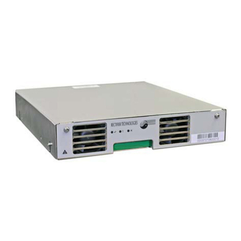
Rectifier
Rectifier RT9- 24V Installation, operation and technical manual
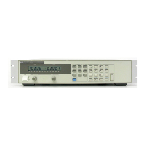
Agilent Technologies
Agilent Technologies 6641A operating guide
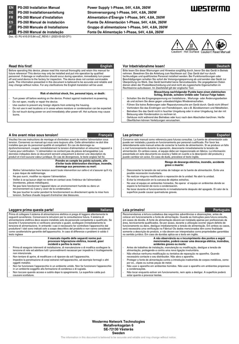
Westermo
Westermo PS-260 manual
Lumel
Lumel ZS20 quick start guide
Extech Instruments
Extech Instruments 382222 user manual

Monster
Monster JP 800 Instructions and warranty information


