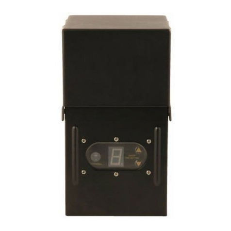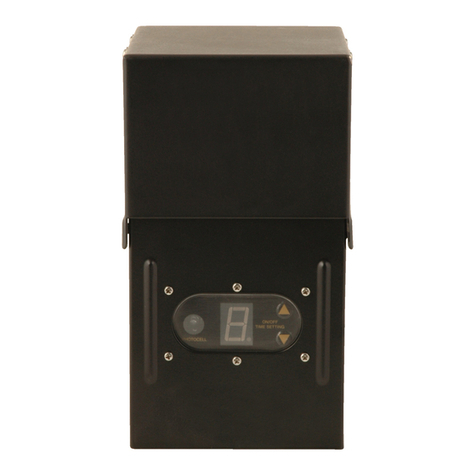
OWNERS MANUAL
PLEASE READ THESE INSTRUCTIONS BEFORE
INSTALLING YOUR CONTROL UNIT
PARTS LIST
a) Control unit –1 pcs
b) Plastic Plug Anchor –4 pcs
c) Black Steel Mounting Screws –2 pcs
d) White Steel Screws –2 pcs
INSTALLATION AND OPERATION
1. Carefully remove all contents from box and set
aside. Due to the heavy weight of the control
box, ensure that the designated mounting surface
can handle the control box weight.
2. On the bottom of the control box locate the three
screw terminals. Using a Phillips head screw
driver remove two of the screws along with the
washer and square copper plate. Insert the low
voltage cable end with the ring type terminals
onto the two machine screws that were removed.
Make sure the washer and copper plates are
included and will cover the wire terminals when
replaced onto the control box. (Refer to the
figure above) Gently tighten the screws with the
washer and copper plates back into the control
box. Do not over tighten screws to avoid
stripping.
3. Mount the unit on a wood, brick or concrete
surface. Install the Black Steel Screws first and
install the transformer onto the screws. When
the transformer is securely in place install the
White Steel Screws in the bottom wing screw
holes. The plastic screw anchors may be
needed depending on the type of mounting
surface. Place transformer unit at least 12” off
the ground.
CONTROL UNIT OPERATION
This control unit uses a 24 hour mechanical timer.
Once the control unit is mounted and the low voltage
cable is set up you can set the timer.
TIMER INSTRUCTIONS
1. Set the current time of day by turning the outside
numbered dial clockwise. Align the current time of
day with the arrow on the inside ring. Make sure that
the switch above the timer is in the RIGHT position to
use the mechanical timer.
2. To set “ON” hours press down the gray pins that
represent that period of time. Each gray pin
represents 15 minutes. Example: If you would like
the landscape lighting to be on from 6pm to 6am, you
would need to press down all the pins between 6pm
and 6am, and leave all the other gray pins in the
raised position.
3. To override timer program, place black slide in
the “ I ” position(the LEFT position). Timer will remain
“ON” until slide is returned to the automatic timer
position ( V )( (the RIGHT position).
4. Place black slide control in automatic timer
position ( V ). Your program will repeat every 24
hours.
*Note- If you are having trouble raising or lowering
the pins, try gently using a ball point pen.
SPECIFICATIONS
INPUT -- AC125V 60HZ
OUTPUT : AC12V
MAX LOAD : 125 WATTS
IMPORTANT
Units installed near swimming pools should be
plugged into a GFCI protected outlet and the control
unit should be mounted at least 3 meters or 10 feet
away from the inside edge of the pool.
If mounting the control unit on brick or concrete, drill
a 3/16” hole and insert the plastic anchor before
hanging.
DO NOT overload the control unit by exceeding the
wattage of the control unit. The total wattage of the
lights (sum of the wattage of each bulb in the system)
should be equal or less than the wattage of the
control unit. Check the display box or back of control
unit for wattage of transformer.

