Moore HCS User manual

HCS
HCS
March 2014
225-740-00G
HART ®Concentrator System
HART-to-MODBUS RTU Converter
HART ®Concentrator System
HART-to-MODBUS RTU Converter

Table of Contents
Introduction ............................................................................................................................................. 4
About this Manual ............................................................................................................ 4
The HCS .......................................................................................................... 4
Model and Serial Numbers............................................................................................... 4
Inputs ............................................................................................................................... 4
Outputs............................................................................................................................. 4
TX Power Supply.............................................................................................................. 4
Specifications ................................................................................................. 5
Dimensions ...................................................................................................................... 6
Terminal Designation Table .............................................................................................. 6
Hooking-Up the HCS Using the TX Power Supply .......................................................... 7
Hooking-Up the HCS Using an External Power Supply ................................................... 8
HCS PC Hook-Up Diagram............................................................................. 9
Factory Default Configuration....................................................................... 9
Configuring the HCS .................................................................................... 10
Installing the Configuration Software ............................................................................. 10
Connecting the HCS to the PC ...................................................................................... 10
Selecting Model Type ..................................................................................................... 10
Necessary Equipment Table........................................................................................... 10
PC Configuration Software Summary ........................................................ 11
Menu and Tool Bar Legend ........................................................................................... 12

Configuration Screens................................................................................. 12
HART ............................................................................................................................. 12
MODBUS ....................................................................................................................... 13
HART Devices................................................................................................................ 15
Status of HART Devices................................................................................................. 15
MODBUS Register Definitions..................................................................... 16
HART Status Information............................................................................. 25
Installation..................................................................................................... 26
Mounting the HCS.......................................................................................................... 26
Making the Electrical Connections................................................................................. 26
Recommended Ground Wiring Practices....................................................................... 26
CE Conformity................................................................................................................ 26
Power Sourcing Parameters for General Locations, Intrinsically Safe and
Non-Incendive/Type N Applications ............................................................................... 26
Operation....................................................................................................... 27
Maintenance................................................................................................................... 27
Customer Support........................................................................................ 27
Appendix A: HCS Legacy Configuration ....................................................A1
Appendix B: HCS Legacy Configuration ....................................................B1

HCS
4 The Interface Solution Experts
HART®Concentrator System
HART-to-MODBUS RTU Converter
Introduction
This is the user’s manual for the Moore Industries
HCS HART® Concentrator System. It contains all of
the information needed to configure, install, operate
and maintain this instrument.
About this Manual
Pay particular attention wherever you see a “Note”,
“Caution” or “WARNING ”.
Note– Information that is helpful for a procedure, con-
dition or operation of the unit.
Caution– Hazardous procedure or condition that
could damage or destroy the unit.
WARNING– Hazardous procedure or condition that
could injure the operator.
The HCS
The HCS HART®Concentrator System converts
a HART digital signal to a serial MODBUS RTU
(RS-485 or RS-232, depending on Output type
ordered) communication protocol. This allows HART
transmitters and valves to interface directly with
MODBUS-based monitoring and control systems.
The HCS uses the following HART commands to
collect its data.
Command 0 Read transmitter unique identifier
Command 3 Read all dynamic variables and current
Command 13 Read tag, descriptor, date
Command 48 Read additional transmitter status
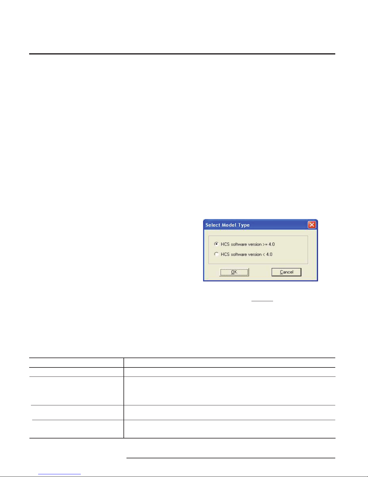
The 3rd generation HCS is now compatible with HART
7 protocol by the release of new HCS firmware v5.2.
This version of the HCS is compatible with HART
5, 6 and 7, however it does not support ALL of the
new features available in HART 6 and 7. Appendix
B provides more details of HART compatibility for all
generations of HCS.
* HART is a registered trademark of the HART Communication Foundation
Model and Serial Numbers
Moore Industries uses the model and serial numbers
of our instruments to track information on each unit
that we sell and service. If a problem occurs with
your HCS, check for a tag affixed to the unit listing
these numbers. Supply the Customer Support
representative with this information when calling.
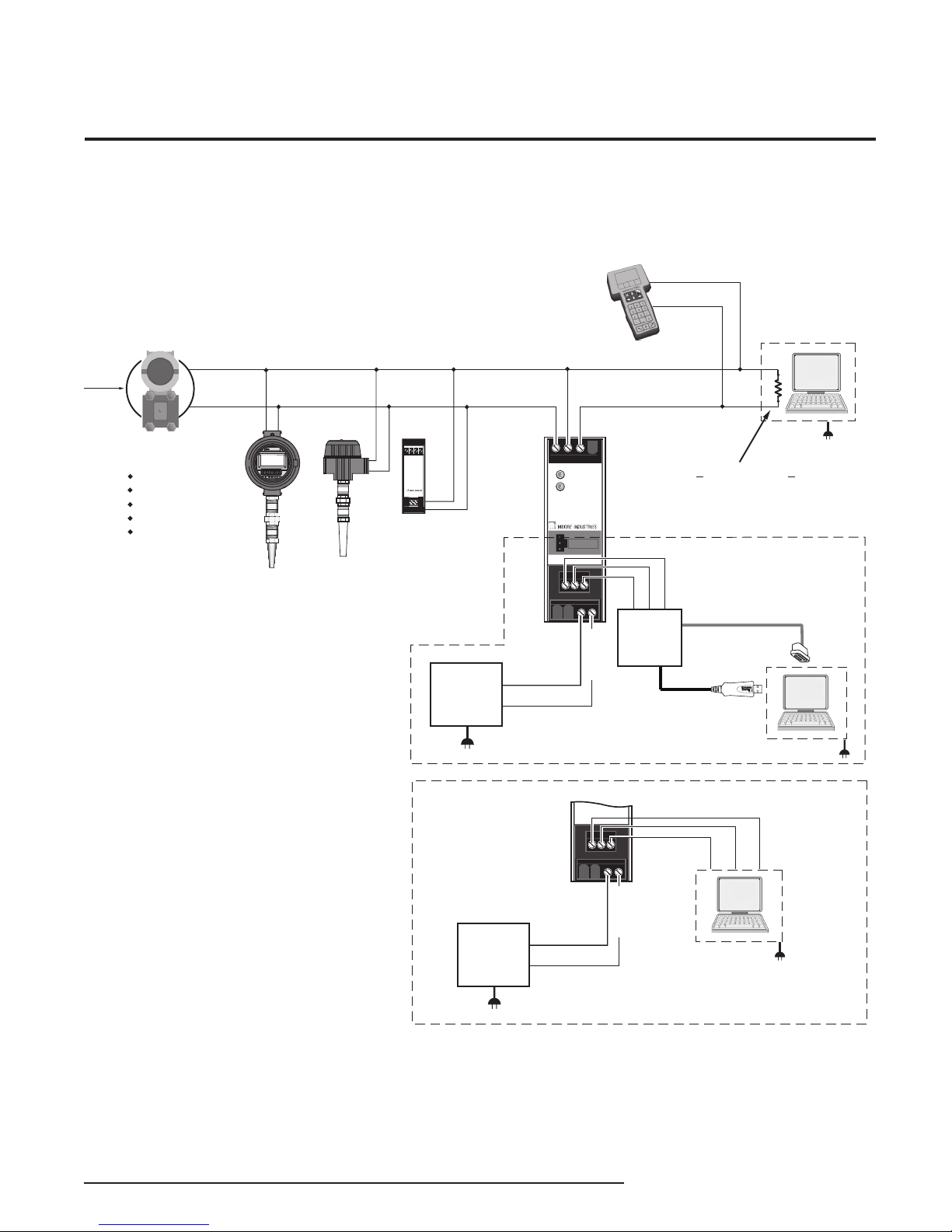
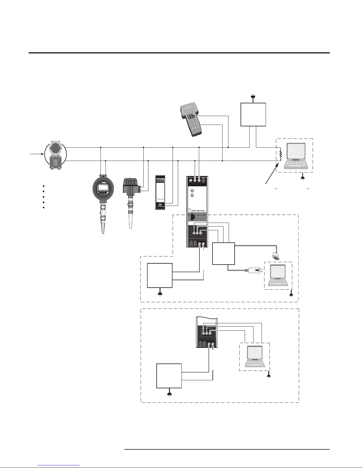
Inputs
The HCS is equipped with one input channel. This
handles up to 16 HART devices in multidrop mode.
In a digital multidrop HART network, up to 16 HART
instruments digitally communicate on the same wires.
The HCS can be set to monitor any or all instruments
and/or valves within the network. Only one MODBUS
address and one communication link is needed to
send the process and diagnostic data from up to 16
HART devices to a MODBUS host.
The instrument is equipped with a READY LED to
indicate the health of the unit and an INPUT LED
to indicate status of HART communication to the
attached HART devices.
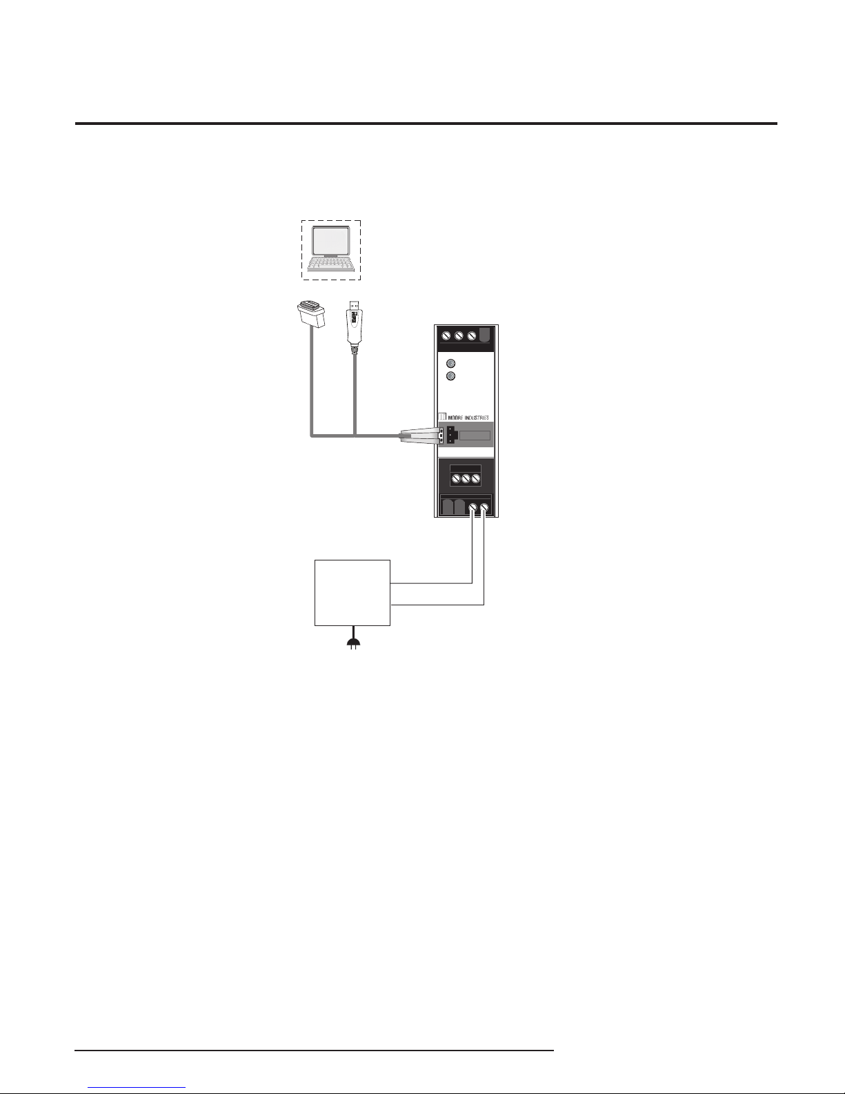
Outputs
The HCS offers a standard RS-485 or RS-232 port
(depending on Output type ordered) that supports the
MODBUS RTU protocol.
MB232
Allows for standard MODBUS RTU protocol interface
over a RS-232 port.
MB485
Allows for standard MODBUS RTU protocol interface
over a RS-485 port.
TX Power Supply
A transmitter excitation power supply (regulated
23.2Vdc ±3%@24mA, maximum) is standard on the
HCS. You may access it at the terminals shown in
Figure 3.

The Interface Solution Experts 5
HCS
HART®Concentrator System
HART-to-MODBUS RTU Converter
Specifications
Input Accuracy: Reflects the
accuracy of the HART field
device
Input Impedance: Transmit
Mode: 150 ohms;
Receive Mode: Less than
5kohms
Isolation: 1000Vrms
between case, input, output
and power terminals and
will withstand 1500Vac
dielectric strength test for one
minute continuous with no
breakdown
Power Supply: 9-30DC
+TX Power Supply: 23.2Vdc
±3%@24mA
Digital Response Time:
Equals the combination of
the HART response time and
the MODBUS response time;
the HART delay is defined
by the HART protocol as
500msec in normal mode
and 333msec in burst mode;
the MODBUS response time
depends on how fast and
how often a MODBUS Master
requests data from the HCS;
the data request to response
time is 50msec
Output Type: Standard
MODBUS RTU protocol
interface over RS-485
(parameters as specified in
U.S. Standard EIA-RS485)
or RS-232 (parameters as
specified in U.S. Standard
EIA-RS232)
Output Protection:
Transient protection on output
Performance
Weight
Performance
(Continued)
Indicators
Ambient
Conditions
Specifications and information subject to change without notice.
Address Range:
Configurable from 1 to 247.
Unit will assume a MODBUS
address of 1 by default
Baud Rate: Interface
supports the following: 300,
600, 1200, 2400, 4800,
9600 and 19.2k. MODBUS
interface will support even,
odd and no parities. Unit will
assume a baud rate of 9600
and no parity by default
Transmission
Range (MB485): Using
24AWG twisted pair wiring,
maximum of 2 mi. (3.2km)@
4800 baud or less; maximum
of 1 mi. (1.6km)@9600 baud;
maximum of 0.5 mi. (0.8km)
@19200 baud
Character Format: One
start bit, 8 data bits and one
stop bit
Data Format: User-
selectable Standard LSW
(Least Significant Word)
or Swapped MSW (Most
Significant Word). Unit will
assume Standard LSW by
default
Power Consumption:
1.5W, nominal; 2W@24Vdc
maximum for units using
transmitter excitation to
supply loop power to a
2-wire instrument
LED Type: Dual color
red/green indicate:
INPUT LED: Input is present
and normal (green); input
signal is not found (red)
READY LED: Instrument
is ready for operation and
configuration (green);
instrument has encountered
an internal problem (red)
Operating and Storage
Range:
-40°C to +85°C
(-40°F to +185°F)
Relative Humidity:
0-95%, non-condensing
RFI/EMI Immunity
(Standard):
10V/m@80-1000MHz, 1kHz
AM, when tested according
to IEC61326
RFI/EMI Immunity
(with -RF Option):
20V/m@80-1000MHz, 1kHz,
when tested according to
IEC61326
Noise Rejection: Common
Mode: 100dB@50/60Hz
290 g (10.2 oz)
Table of contents
Other Moore Media Converter manuals
Popular Media Converter manuals by other brands

H&B
H&B TX-100 Installation and instruction manual

Bolin Technology
Bolin Technology D Series user manual

IFM Electronic
IFM Electronic Efector 400 RN30 Series Device manual

GRASS VALLEY
GRASS VALLEY KUDOSPRO ULC2000 user manual

Linear Technology
Linear Technology DC1523A Demo Manual

Lika
Lika ROTAPULS I28 Series quick start guide

Weidmuller
Weidmuller IE-MC-VL Series Hardware installation guide

Optical Systems Design
Optical Systems Design OSD2139 Series Operator's manual

Tema Telecomunicazioni
Tema Telecomunicazioni AD615/S product manual

KTI Networks
KTI Networks KGC-352 Series installation guide

Gira
Gira 0588 Series operating instructions

Lika
Lika SFA-5000-FD user guide