Manual Part No: 930158-01 MD Electric Range - 6 –
Manual Rev No: 1
SPECIFICATION
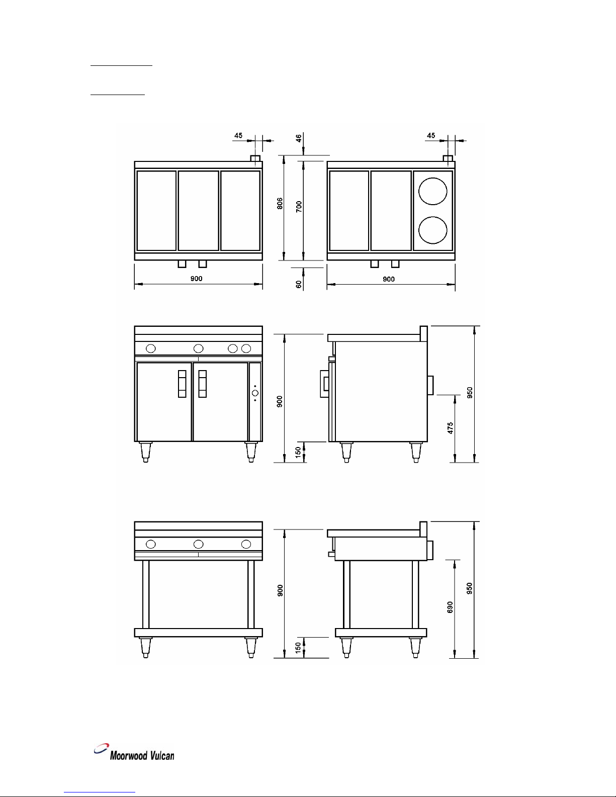
900 Range - 3 Solid Plates - (MLE90R-F-S)
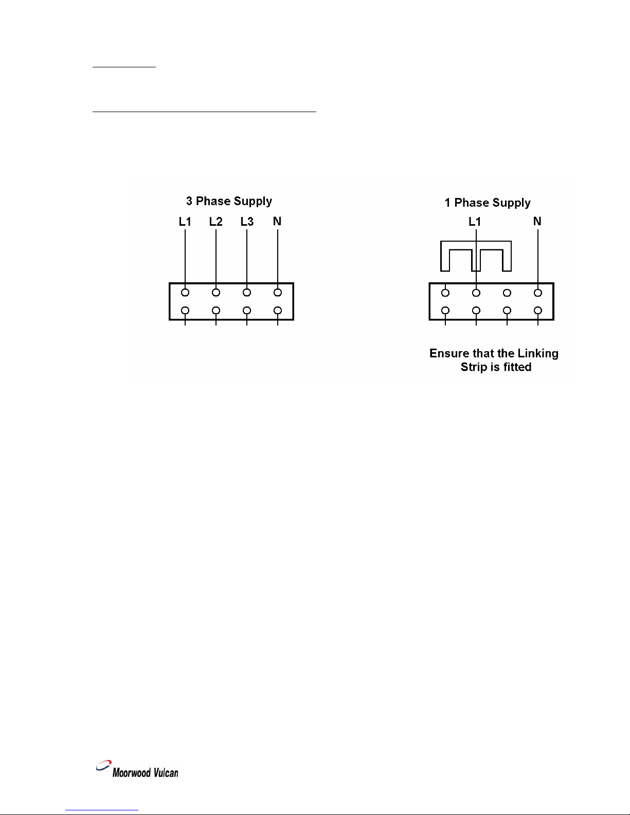
Supply - 400V, 50Hz, 3 Phase (alternative 240V, 50Hz, 1 Phase)
Phase Loading - L1 - 6.0kW, L2 - 6.0kW, L3 - 3.0kW (1 Phase - 15.0kW)
Oven - 6.0kW
Solid Hotplate - 3 x 3.0kW
Total - 15.0kW
Weight - 128kg
900 Range - 2 Solid Plates, 2 Round Hotplates - (MLE90R-F-RS)
Supply - 400V, 50Hz, 3 Phase (alternative 240V, 50Hz, 1 Phase)
Phase Loading - L1 - 6.0kW, L2 - 6.0kW, L3 - 3.5kW (1 Phase - 15.5kW)
Oven - 6.0kW
Solid Hotplate - 2 x 3.0kW
Round Hotplate- Front - 1.5kW, Rear - 2kW
Total - 15.5kW
Weight - 127kg
600 Range - 2 Solid Plates - (MLE60R-F-S)
Supply- 400V, 50Hz, 3 Phase (alternative 240V, 50Hz, 1 Phase)
Phase Loading - L1 - 4.0kW, L2 - 3.0kW, L3 - 3.0kW (1 Phase - 10.0kW)
Oven - 4.0kW
Solid Hotplate - 2 x 3.0kW
Total - 10.0kW
Weight - 98kg
600 Range - 1 Solid Plate, 2 Round Hotplates - (MLE60R-F-RS)
Supply - 400V, 50Hz, 3 Phase (alternative 240V, 50Hz, 1 Phase)
Phase Loading - L1 - 4.0kW, L2 - 3.0kW, L3 - 3.5kW (1 Phase - 10.5kW)
Oven - 4.0kW
Solid Hotplate - 3.0kW
Round Hotplate- Front - 1.5kW, Rear - 2.0kW
Total - 10.5kW
Weight - 97kg
900 Boiling Table - 3 Solid Plates - (MLE90BT-F-S)
Supply - 400V, 50Hz, 3 Phase (alternative 240V, 50Hz, 1 Phase)
Phase Loading - L1 - 3.0kW, L2 - 3.0kW, L3 - 3.0kW (1 Phase - 9.0kW)
Solid Hotplate - 3 x 3.0kW
Total - 9.0kW
Weight - 54kg