Mopar 82209992 User manual

123456789012345678901234567890121234567890123456789012345678901
1
2345678901234567890123456789012123456789012345678901234567890
1
1
2345678901234567890123456789012123456789012345678901234567890
1
1
2345678901234567890123456789012123456789012345678901234567890
1
1
2345678901234567890123456789012123456789012345678901234567890
1
1
2345678901234567890123456789012123456789012345678901234567890
1
1
2345678901234567890123456789012123456789012345678901234567890
1
1
2345678901234567890123456789012123456789012345678901234567890
1
1
2345678901234567890123456789012123456789012345678901234567890
1
1
2345678901234567890123456789012123456789012345678901234567890
1
1
2345678901234567890123456789012123456789012345678901234567890
1
1
2345678901234567890123456789012123456789012345678901234567890
1
1
2345678901234567890123456789012123456789012345678901234567890
1
123456789012345678901234567890121234567890123456789012345678901
INSTALLATIONINSTRUCTIONS
Professional Installation is Recommended
Technical Support
ForAuthorized Dealers - (800) 34-MOPAR
Hours: 9:00 a.m. - 6:00 p.m. EST Monday thru Friday
10:00 a.m. - 2:00 p.m. EST Saturday
1031263
REV.A
5/06 K6859657
2007 Jeep Wrangler (JK)
Security System
Note: ForEVSIinstallations,bothFactoryRKEKeyfobsare
requiredforoptionprogramming&Driver’sDoorPriority
Unlockfeaturemust be enabled.

2
This device complies with part 15 of the FCC rules and with RSS-210 of the
industry Canada. Operation is subject to the following two conditions: (1) this
device may not cause harmful interference, and (2) this device must accept
any interference received, including interference that may cause undesired
operation.
This product was manufactured in environmentally friendly manufacturing
facility and may contain certain recycled materials. All materials meet or
exceed original specifications for quality and reliability.
JeepWrangler(JK)
Security System
TableofContents
Vehicle Preparation...................................................................................4
Module Preparation...................................................................................5
Custom Harness Installation.....................................................................6
System Programming.............................................................................10
EVS I Programming................................................................................10
EVS II Programming...............................................................................12
Option Bank Chart...................................................................................13
System Testing.........................................................................................14
Reassembly..............................................................................................14
System Layout..........................................................................................15
123456789012345678901234567890121234567890123456789012345678901
1
2345678901234567890123456789012123456789012345678901234567890
1
1
2345678901234567890123456789012123456789012345678901234567890
1
1
2345678901234567890123456789012123456789012345678901234567890
1
1
2345678901234567890123456789012123456789012345678901234567890
1
1
2345678901234567890123456789012123456789012345678901234567890
1
1
2345678901234567890123456789012123456789012345678901234567890
1
1
2345678901234567890123456789012123456789012345678901234567890
1
1
2345678901234567890123456789012123456789012345678901234567890
1
1
2345678901234567890123456789012123456789012345678901234567890
1
1
2345678901234567890123456789012123456789012345678901234567890
1
1
2345678901234567890123456789012123456789012345678901234567890
1
1
2345678901234567890123456789012123456789012345678901234567890
1
123456789012345678901234567890121234567890123456789012345678901
Note: For EVS I installations, both Factory RKE
Keyfobs are required for option programming &
Driver’s Door Priority Unlock feature must be enabled.

3
PARTS REQUIRED
PartNumber82209992(EVSI)or82209991(EVSII)
5A 1X 15A 1X 1X 5X
Owner's Manual
VehicleRemote Star t System
TM
FeaturingPowerCodeTechnology
FortheUltimate inComfort,Convenience andSecurity
TM
®
TOOLS REQUIRED
10mm 1/4”
VEHICLEPREPARATION
1. Lower one or more of the passenger windows so the keys do not get locked
in the vehicle.
2. Disconnect and isolate the negative battery cable. The battery will need to be
re-connected before programming.
3. EVS I System installation requires 2 working factory RKE keyfobs for
programming options.
TM
T-
20
12345678901234567890123456789012123
1
234567890123456789012345678901212
3
1
234567890123456789012345678901212
3
1
234567890123456789012345678901212
3
1
234567890123456789012345678901212
3
1
234567890123456789012345678901212
3
1
234567890123456789012345678901212
3
1
234567890123456789012345678901212
3
1
234567890123456789012345678901212
3
1
234567890123456789012345678901212
3
1
234567890123456789012345678901212
3
12345678901234567890123456789012123
EVS II - additional parts
ARM DISARM
2X 2X each
1234
1
23
4
1
23
4
1234
T20/T30

4
VehiclePreparation
Removedriver’ssidelowerdashpanels,
&steeringcolumnshroud.
A. Pull down on lower dash. Panel is
held by clips. Start at the top corners.
Remove panel.
B. Remove (3) bolts holding metal panel
in place. Pull up on the panel to
remove.
C. Remove lower plastic dash panel.
Panel is held by clips.
D. Remove (3) screws from steering
column shroud. Separate and remove
steering column shroud.
E. Removedriver’sside kickpanel/sill
plate. Panel is held on by clips.
Overview
The security module harness will interface with the existing ignition switch connec-
tor, horn, parking lights, power doorlock & door trigger connections, and a ground
termination.

5
Module Preparation
Place fuses into the control module.
A. Observe fuse amperage ratings. Place
the 5 Amp fuse into the “Main B+”
location. Place the 15 Amp fuse into
the positive “PK LIGHTS” location.
Install DNA into the control module.
B. Insert DNA into the control module.
Ensure the DNA assembly snaps
completely in place and no circuit
board pins get bent while closing.
DNA

6
Custom Harness Installation
Ignition switch connector
A. Locate ignition switch connector,
directly behind the ignition switch.
Release the secondary lock. While
pushing on main release, remove
connector from ignition switch.
B. Connect the harness 5-way female
connector to the vehicle’s ignition
switch.
C. Connect the harness 5-way male
connector to the vehicle’s 5-way
ignition connector previously
removed from the ignition switch.
Ground
D. Using a supplied 1/4” screw,
secure the black ground wire with
ring terminal to the driver’s side left
kickpanel metal.
Parking Light Connection
E. LocatetheWhite/Violet (L217)wirein
harness, found low in the left kick
panel area. Center-splice the
harness Yellow wire into this wire,
following the center-splice proce-
dure as shown. This wire will show
+12V when the parking lights are
turned on.
Center-Splice Procedure

7
ArmWireConnection(EVSIonly!)
F. Locate the Lt Green/Grey wire in the driver kick
panel. Thiswirewill show+12 voltswhenthedoors
are locked using the keyfob. Center-splice
the harness Lt Blue wire into this wire, fol-
lowing the center-splice procedure.
DisarmWire Connection(EVS Ionly!)
G. LocatetheTan/Brown wire in thedriverkick
panel. Thiswill willshow+12 volts whenthe doors
are unlocked on the first press of the unlock but-
tonon the keyfob. Center-splice theharnessBrown
wire into this wire, following the center-splice pro-
cedure.
Unlock Sense Wire Connection (EVS I only!)
H. Locate the Tan/Brown wire in in the passenger kick
panel. This wire will show +12 volts when the doors
are unlocked only on the second press of the unlock
button on the keyfob. Center-splice the harness Lt
Green wire into this wire, following the center-splice
procedure.
DoorTrigger Connection
I. Locate theYellow/White dome light
feed wire (M24), found at the
underdash courtesy light. Center-
splice to the White wire on the
main security harness.
PowerDoorLockConnections - UsedforEVS Ionly.
SkiptoStepIforEVSII.

8
LED
J. Drill 9/32” hole in trim panel as
shown in diagram. Exact place-
ment needs to be determined
before drilling. Ensure there is
nothing on the backside of the
panel and there is enough depth for
theLED.
K. Routethe remaining Dk Green wire
through the cowl panel and into the
engine compartment through an existing
grommet.
HornConnections
L.Locate the Grey/Yellow(X21)wire in the
green “C” connector (pin #18) found
underneath the TIPM module. Center-
splice the relay harness Grey wire (pin
30) into this wire, following the center-
splice procedure. Solder the connection.
This wire will show +12V when the horn
is activated.
M. Connect the relay harness Red wire (pin
87) to the positive battery post.
N. Route the remaining relay harness Dk
Greenwire (pin 85) to the Dk Green (-)
HORN output wire on the main security
harness. Solder the connection.

9
Security Module Connections
O. Connect the 24-way connector into
the PC-12 Security module. Also,
connect the antenna connector (EVS II
Systems only) on end opposite the
main harness connector.
24-Way
Antenna
87
8685
30
87a
(+)
20A Fuse
Connect to (-)HORN output (pin #21)
from security module
Dk Green wire Dk Green
Grey
Red
Connect to Grey/Yellow (X21) at
TIPM Green “C” Connector (pin #18)

10
Option Programming.
The remote security system has several installer programmable options which
can be changed to accomodate different circumstances. In most cases, there
will be a need to change option settings (i.e. adjustment of shock sensor
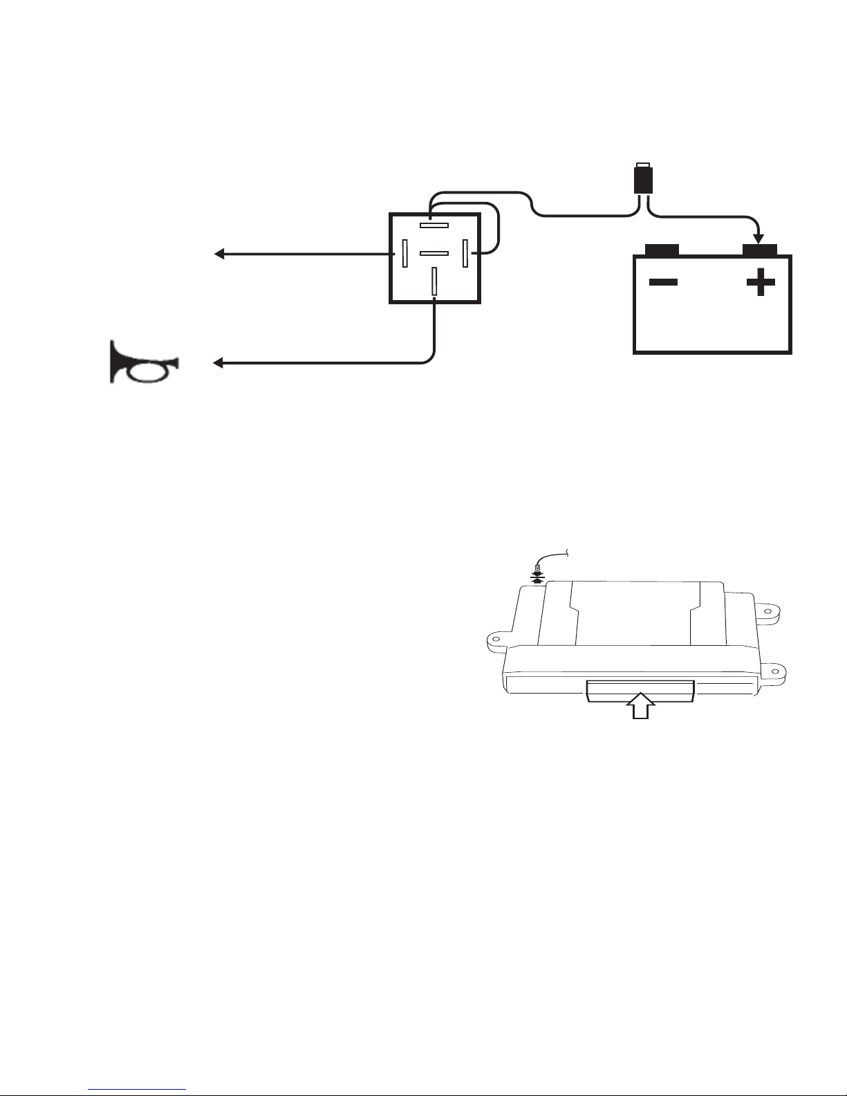
sensitivity, horn pulse output duration, etc).
A. Open the driver’s door.
B. Turn the ignition to the “on” position.
C. Press and hold the programming/override button; After 10 seconds the
parking lights will flash 3 times indicating the system is now in learn
mode.
D. Release the programming button.
E. Press and release the programming button once more; The parking
lights will flash 4 times indicating the system has entered Option Bank 1.
System Programming
Notes:
1. Reconnect the negative battery terminal prior to programming.
2. EVS I System installation requires 2 working factory RKE keyfobs for
programming options & Driver’s Door Priority Unlock feature to be
enabled for proper operation of the security system. Refer to vehicle’s
Service Manual.
3. This system has 2 option banks. Bank 1 has 8 options, and Bank 2
has 4 options. Refer to the Option Bank Chart for details.
To change the setting of an option: (EVS I Systems only)
A. Press the door trim “Lock” switch or, if the vehicle’s door lock feature is
non-functional with the ignition turned on, press the factory keyfob
“Lock” button (of the keyfob that is not in the ignition cylinder) to advance
to the desired option (refer to the Option Bank Chart).
The parking lights will flash a number of times indicating which option
is selected (i.e. Two flashes indicates that option number two has been
selected).
B. Press the door trim “Unlock” switch to change the setting of an option..
The status LED indicates the setting of the option; LED ON indicates
that the option is on, LED OFF indicates that the option is off.
C. To advance to Option Bank 2, at any point while in Option Bank 1, press
and release the programming/override button to advance to option bank
number two. The parking lights will flash 5 times indicating the system
has entered Option Bank 2.
To return back to Option Bank 1, press and release the programming/
override button once again (4 flashes).

11
Shock sensor setting: (EVS I Systems only)
(Ensure module is mounted before adjustment!)
The “Lite-touch” and “Full shock” sensor settings are always the first and
second options, respectively, in Option Bank 1. To change the shock
sensor setting, follow these steps:
A. Make sure the driver’s window is rolled down.
B. Enter Option Learn Mode, Option Bank 1, as shown on page 10.
C. Go to option #1 for Lite-touch (parking lights flash 1 time).
D. Close all doors (wait for domelight to turn off).
E. Press the door trim “Unlock” switch to increase sensitivity and press the
door trim “Lock” switch to decrease sensitivity.
F. Test the shock sensor sensitivity (while in option learn mode) by
applying an impact with an open hand to the windshield. Caution -
make sure to remove articles of jewelry to avoid scratching or
breaking glass.
The parking lights will flash each time an impact is detected that is
greater than the current setting.
G. Once the desired Lite-touch sensitivity is achieved, open a door to
advance to the Full shock option by pressing the door trim “Lock” switch
or, if the vehicle’s door lock feature is non-functional with the ignition
turned on, press the factory keyfob “Lock” button (parking lights flash 2
times). Repeat steps D through F to set Full shock sensitivity.
H. Open a door to continue with “To change the setting of an option” on
page 10 (if necessary).

12
To change the setting of an option: (for EVS II Systems only)
A. Enter Option Learn Mode, Option Bank 1, as shown on page 10.
B. Press both “Arm” & “Disarm” buttons together to advance to the desired
option (refer to the Option Bank Chart).
The parking lights will flash a number of times indicating which option is
selected (i.e. Two flashes indicates that option number two has been
selected).
C. Press the “Arm” button to change the setting of an option..
The status LED indicates the setting of the option; LED ON indicates that
the option is on, LED OFF indicates that the option is off.
D. To advance to Option Bank 2, at any point while in Option Bank 1, press
and release the programming/override button to advance to option bank
number two. The parking lights will flash 5 times indicating the system
has entered Option Bank 2.
To return back to Option Bank 1, press and release the programming/
override button once again (4 flashes).
Shock sensor setting: (EVS II Systems only)
(Ensure module is mounted before adjustment!)
The “Lite-touch” and “Full shock” sensor settings are always the first and
second options, respectively, in Option Bank 1. To change the shock sensor
setting, follow these steps:
A. Make sure the driver’s window is rolled down.
B. Enter Option Learn Mode, Option Bank 1, as shown on page 10.
C. Press “ARM” & “DISARM” buttons together to go to option #1 for Lite-
touch (parking lights flash 1 time).
D. Press the “ARM” button to increase sensitivity and press the “DISARM”
button to decrease sensitivity.
E. Test the shock sensor sensitivity (while in option learn mode) by applying
an impact with an open hand to the windshield. Caution - make sure to
remove articles of jewelry to avoid scratching or breaking glass.
The parking lights will flash each time an impact is detected that is
greater than the current setting.
F. Once the desired Lite-touch sensitivity is achieved, press “ARM” &
“DISARM” buttons together to advance to option #2 for Full shock
(parking lights flash 2 times). Repeat steps D through Eto set Full shock
sensitivity.
G. Press “ARM” & “DISARM” buttons together to advance to the next
option (if necessary).

13
Option Bank 1 – 4 flashes
1 – Lite-touch adjustment
2 – Full shock adjustment
3 – Horn pulse short/long*
On - Short output, Off - Long output...............................................................................On
4 – Selectable chirps
Enables arming/disarming confirmation chirps.........................................................On
5 – Silent choice................................................................................................................On
On – Confirmation chirp on second press of transmitter button
Off – Confirmation chirp on first press of transmitter button.
Requires option #4(above) to be ON............................................................................On
6 – Not used
7 – Optional alarm disable
Disables security functionality........................................................................................Off
8 – Noise control
Limits alarm trips to 5 per zone.....................................................................................On
Option Bank 2 – 5 flashes
1 – Door ajar switch input polarity
LED On – Positive, LED Off – Negative........................................................................Off
2 – Unlock switch sense input polarity
LED On – Positive, LED Off – Negative........................................................................On
3 - Not used
4 – Door ajar input entry delay
(5) Five Second entry delay. ...........................................................................................Off
FACTORY SETTING
FACTORY SETTING
Option Programming - Option Banks
*If the horn does not honk when the systems is triggered, turn off Option #3 in
Option Bank #1.

14
Dash reassembly.
A. Reverse the dash dissassembly procedure.
Reassembly
Component mounting.
A. Mount security module to existing underdash braces or wire harnesses
using the supplied wire ties. Avoid moving parts (steering column, brake
pedal assembly).
B. Using supplied wire ties, secure the security module harness to existing
wire harnesses under the left side of the dash. Ensure no wires will become
entangled in the steering column knuckle and that they are not visible to
vehicle occupants.
C. Using a supplied wire tie, secure the programming/override button to the
harness leading to the vehicle’s diagnostic connector.
Consistency in mounting this switch in the same place
every time will make it easier to find in case the system
comes back for service. Also, the dash will not have to
be disassembled to access it. Ensure that the place-
mentoftheprogramming/overridebuttonisindicated
intheOwner’smanualandthecustomerknowswhere
itislocatedand can accessit..
SECURITYSYSTEMARM/DISARM
USINGFACTORYRKEKEYFOBS
VERIFYINTERIORDOORTRIMUNLOCKSWITCHDOESNOTDISARMSYSTEM
ALLENTRYPOINTSTRIPALARMCYCLE
STATUSINDICATORFLASHESWHENARMED
SHOCKSENSORSETTINGS(LITE-TOUCH&FULLSHOCK)
Security Function Checklist
PROGAMMING/OVERRIDEBUTTONDISARMSSYSTEMWITHIGNITIONON

15
PROGRAMMING/
OVERRIDE BUTTON
FACTORY
IGNITION
HARNESS
MALE
IGNITION SWITCH
CONNECTOR
FEMALE
IGNITION SWITCH
CONNECTOR
05189810AA
PC-12 MODULE
SECURITY DNA
LED
GROUND
FACTORY
HARNESS
PARKING LIGHT CONNECTION:
LEFT SILL PANEL HARNESS
White/Violet (L217)
JEEP WRANGLER (JK) SECURITY SYSTEM LAYOUT
Harness Yellow to
LT BLUE (ARM)
BROWN (DISARM)
LT GREEN (UNLOCK SENSE)
WHITE
(DOOR TRIGGER)
To Lt Green/Grey at
Driver kick panel
To Tan/Brown at
Driver kick panel
To Tan/Brown at
Passenger kick panel
DOOR TRIGGER CONNECTION:
T
o Yellow/White (M24) at
underdash courtesy light
05140464AA
Grey/Yellow (X21) Pin #18
GREEN “C”CONNECTOR at TIPM
Dk Green
87
8685
30
87a
20A Fuse
Dk Green
Grey
Red
FACTORY
HARNESS

16
1031263
REV.A
5/06 K6859657
1234567890123456789012345678901212345678901234567890123456789012
1
23456789012345678901234567890121234567890123456789012345678901
2
1
23456789012345678901234567890121234567890123456789012345678901
2
1
23456789012345678901234567890121234567890123456789012345678901
2
1
23456789012345678901234567890121234567890123456789012345678901
2
1
23456789012345678901234567890121234567890123456789012345678901
2
1
23456789012345678901234567890121234567890123456789012345678901
2
1
23456789012345678901234567890121234567890123456789012345678901
2
1
23456789012345678901234567890121234567890123456789012345678901
2
1
23456789012345678901234567890121234567890123456789012345678901
2
1
23456789012345678901234567890121234567890123456789012345678901
2
1
23456789012345678901234567890121234567890123456789012345678901
2
1
23456789012345678901234567890121234567890123456789012345678901
2
1234567890123456789012345678901212345678901234567890123456789012
INSTRUCCIONES PARA LA INSTALACIÓN
Es conveniente que la instalación esté a cargo de un profesional.
Sistemadeseguridadpara
Jeep Wrangler (JK)
Nota: Para instalar el EVS I son necesarios los dos llaveros
provistos de fábrica, y debe estar habilitada la función que da
prioridadalapuertadelconductorparadestrabarlasdemás.
Servicio técnico
Para comunicarse con los representantes autorizados
(800)34-MOPAR
Horario: lunes a viernes de 9 a 18, Hora del Este
Sábados de 10 a 14, Hora del Este

17
Este aparato cumple con la parte 15 de las normas de la Comisión Federal de Comunicaciones de
los EE.UU. (FCC) y con la norma industrial de Canadá RSS-210. El funcionamiento depende de
las dos condiciones a continuación: (1) que este aparato no provoque interferencias nocivas y (2)
que este aparato deba aceptar interferencias recibidas, como aquéllas que puedan provocar un
funcionamiento no deseado.
12345678901234567890123456789012123456789012345678901234567890
1
234567890123456789012345678901212345678901234567890123456789
0
1
234567890123456789012345678901212345678901234567890123456789
0
1
234567890123456789012345678901212345678901234567890123456789
0
1
234567890123456789012345678901212345678901234567890123456789
0
1
234567890123456789012345678901212345678901234567890123456789
0
1
234567890123456789012345678901212345678901234567890123456789
0
1
234567890123456789012345678901212345678901234567890123456789
0
1
234567890123456789012345678901212345678901234567890123456789
0
1
234567890123456789012345678901212345678901234567890123456789
0
1
234567890123456789012345678901212345678901234567890123456789
0
1
234567890123456789012345678901212345678901234567890123456789
0
1
234567890123456789012345678901212345678901234567890123456789
0
12345678901234567890123456789012123456789012345678901234567890
Nota: Para instalar el EVS I son necesarios los dos llaveros
provistos de fábrica, y debe estar habilitada la función que da
prioridadalapuertadelconductorparadestrabarlasdemás.
Este producto está fabricado en instalaciones que no dañan el ambiente y puede
contener ciertos materiales reciclados. Todos los materiales cumplen con las
especificaciones originales de calidad y confiabilidad, o las superan.
Sistemadeseguridadpara
Jeep Wrangler (JK)
Índice
Preparación del vehículo...............................................................................19
Preparación del módulo................................................................................20
Instalaciónindividualizada delmazo decables...............................................21
Programación del sistema.............................................................................25
Programación del EVS I...............................................................................25
Programación del EVS II.............................................................................27
Tabla de los bancos de opciones..................................................................28
Pruebas al sistema........................................................................................29
Rearmado ...................................................................................................29
Disposicióndelsistema.................................................................................30

18
PIEZASNECESARIAS
Piezanúmero82209992(paraEVS I)o82209991(paraEVSII)
5A x1 15A x1 x1 x5
Owner's Manual
VehicleRemote Star t System
TM
FeaturingPowerCodeTechnology
FortheUltimate inComfort,Convenience andSecurity
TM
®
HERRAMIENTASNECESARIAS
10mm 1/4”
TM
T-
20
12345678901234567890123456789012123
1
234567890123456789012345678901212
3
1
234567890123456789012345678901212
3
1
234567890123456789012345678901212
3
1
234567890123456789012345678901212
3
1
234567890123456789012345678901212
3
1
234567890123456789012345678901212
3
1
234567890123456789012345678901212
3
1
234567890123456789012345678901212
3
1
234567890123456789012345678901212
3
1
234567890123456789012345678901212
3
12345678901234567890123456789012123
para EVS II - otras piezas
ARM DISARM
x2 x2 de cada uno
1234
1
23
4
1
23
4
1
23
4
1234
T20/T30
PREPARACIÓNDELVEHÍCULO
1. Baje una o dos de las ventanas de los pasajeros por si el vehículo se cierra
ylas llaves quedaranadentro.
2. Desconecte y aísle el cable negativo de la batería. Necesitará reconectar la
bateríaantes de laprogramación.
3. Paraprogramarlasopcionesdurante la instalación delsistemaEVSIson
necesarioslosdosllaveros provistos de fábrica.

19
Preparación del vehículo
Quite los paneles laterales
inferiores del tablero de
instrumentos del lado del conduc-
tor y el anillo de refuerzo de la
columna de dirección.
A. Baje el panel de instrumentos
inferior. El panel está sujetado por
clips. Comience por las esquinas
superiores. Quite el panel.
B. Retire los pernos (3) que
mantienen en su lugar al panel
metálico. Levante el panel para
quitarlo.
C. Quite el panel inferior de plástico
del tablero de instrumentos. El
panel está sujetado por clips.
D. Retire los tornillos (3) del anillo de
refuerzo de la columna de
dirección. Separe y quite el anillo
de refuerzo de la columna de
dirección.
E. Quite el panel lateral inferior /
protector de estribo del conductor.
El panel está sujetado por clips.
Descripción general
El manojo de cables del módulo de seguridad se conectará al conector del
interruptor de encendido, bocina, luces de posición, seguro eléctrico de puertas,
conexiones de disparadores de puertas y terminal de conexión a tierra.

20
DNA
Preparacióndelmódulo
Coloquelosfusiblesenelmódulo de control
A. Observe los amperajes de los fusibles.
Coloque los fusibles de 5 amperes en la
posición “Main B+”. Coloque los fusibles de
15 amperes en la posición positiva de “PK
LIGHTS”.
InstalelaplacadecircuitosDNAenelmódulo
decontrol
B.InsertelaplacaDNAen el módulo de control.
Confirme que el conjunto de la placa DNA
calce completamente y que no se doble
ninguna clavija de la placa de circuitos al
cerrar.
This manual suits for next models
1
Table of contents
Languages:
Other Mopar Security System manuals