Mopar K6859682 User manual

INSTALLATION INSTRUCTIONS
Professional Installation is Recommended
Technical Support
For Authorized Dealers - (800) 34-MOPAR
Hours: 9:00 a.m. - 6:00 p.m. EST Monday thru Friday
10:00 a.m. - 2:00 p.m. EST Saturday
1030928
REV.A
8/05 K6859682
Chrysler PT Cruiser
Security System
123456789012345678901234567890121234567890123456789012345678901
1
2345678901234567890123456789012123456789012345678901234567890
1
1
2345678901234567890123456789012123456789012345678901234567890
1
1
2345678901234567890123456789012123456789012345678901234567890
1
1
2345678901234567890123456789012123456789012345678901234567890
1
1
2345678901234567890123456789012123456789012345678901234567890
1
1
2345678901234567890123456789012123456789012345678901234567890
1
1
2345678901234567890123456789012123456789012345678901234567890
1
1
2345678901234567890123456789012123456789012345678901234567890
1
1
2345678901234567890123456789012123456789012345678901234567890
1
1
2345678901234567890123456789012123456789012345678901234567890
1
1
2345678901234567890123456789012123456789012345678901234567890
1
1
2345678901234567890123456789012123456789012345678901234567890
1
123456789012345678901234567890121234567890123456789012345678901
Note: For EVS I installations, both Factory RKE
Keyfobs are required for option programming &
Driver’s Door Priority Unlock feature must be enabled.

2
This device complies with part 15 of the FCC rules and with RSS-210 of the
industry Canada. Operation is subject to the following two conditions: (1) this
device may not cause harmful interference, and (2) this device must accept
any interference received, including interference that may cause undesired
operation.
This product was manufactured in environmentally friendly manufacturing
facility and may contain certain recycled materials. All materials meet or
exceed original specifications for quality and reliability.
Chrysler PT Cruiser
Security System
Table of Contents
Vehicle Preparation...................................................................................4
Module Preparation...................................................................................6
Custom Harness Installation.....................................................................7
System Programming.............................................................................10
EVS I Programming................................................................................10
EVS II Programming...............................................................................12
Option Bank Chart...................................................................................13
System Testing.........................................................................................14
Reassembly..............................................................................................14
System Layout..........................................................................................15
123456789012345678901234567890121234567890123456789012345678901
1
2345678901234567890123456789012123456789012345678901234567890
1
1
2345678901234567890123456789012123456789012345678901234567890
1
1
2345678901234567890123456789012123456789012345678901234567890
1
1
2345678901234567890123456789012123456789012345678901234567890
1
1
2345678901234567890123456789012123456789012345678901234567890
1
1
2345678901234567890123456789012123456789012345678901234567890
1
1
2345678901234567890123456789012123456789012345678901234567890
1
1
2345678901234567890123456789012123456789012345678901234567890
1
1
2345678901234567890123456789012123456789012345678901234567890
1
1
2345678901234567890123456789012123456789012345678901234567890
1
1
2345678901234567890123456789012123456789012345678901234567890
1
1
2345678901234567890123456789012123456789012345678901234567890
1
123456789012345678901234567890121234567890123456789012345678901
Note: For EVS I installations, both Factory RKE
Keyfobs are required for option programming &
Driver’s Door Priority Unlock feature must be enabled.

3
PARTS REQUIRED
Part Number 82209707 (EVS I) or 82209717 (EVS II)
5A 1X 15A 1X 1X 5X
Owner's Manual
VehicleRemote Start System
TM
FeaturingPowerCodeTechnology
FortheUltimatein Comfort,ConvenienceandSecurity
TM
®
TOOLS REQUIRED
10mm 1/4”
VEHICLE PREPARATION
1. Lower one or more of the passenger windows so the keys do not get locked
in the vehicle.
2. Disconnect and isolate the negative battery cable. The battery will need to be
re-connected before programming.
3. EVS I System installation requires 2 working factory RKE keyfobs for
programming options.
TM
DOOR TRIGGER INPUT HARNESS
T-
20
12345678901234567890123456789012123
1
234567890123456789012345678901212
3
1
234567890123456789012345678901212
3
1
234567890123456789012345678901212
3
1
234567890123456789012345678901212
3
1
234567890123456789012345678901212
3
1
234567890123456789012345678901212
3
1
234567890123456789012345678901212
3
1
234567890123456789012345678901212
3
1
234567890123456789012345678901212
3
1
234567890123456789012345678901212
3
12345678901234567890123456789012123
EVS II - additional parts
ARM DISARM
2X 2X each
1234
1
23
4
1
23
4
1234
T20/T30

4
Vehicle Preparation
Remove driver’s side lower dash
panel, metal dash panel, air bag &
steering column shroud.
A. Remove the lower dash panel by
using a trim stick to release the
catch tabs on the backside of the
panel. The top is held on by clips.
Remove dash panel.
B. Remove (4) screws from metal
panel.
C. Remove (3) screws from steering
column shroud. Seperate and
remove steering column shroud.
D. Remove (1) screw from left dash
panel and remove panel. Discon-
nect connector if necessary.
E. Remove (1) screw from the cluster
cover panel located to the left of
the steering column.
F. Remove (2) screws from the top
corner of the air bag cover.
G. Remove (2) screws from air bag
module. Disconnect connector
after ensuring battery is discon-
nected. Removal of the air bag is
not mandatory, but makes the
installation easier.
Overview
The security module harness will interface with the existing ignition switch connec-
tor, horn, parking lights, power doorlock & door trigger connections, and a ground
termination.

5
Vehicle Preparation - continued
H. Remove left kick panel. Panel is held
on by clips.
I. Remove (2) screws from Driver’s side
visor. Disconnect connector and
remove visor.
J. Remove (1 ) screw from visor holder.
K. Gently remove driver’s “A” pillar.
L. While gently pushing up on the driver’s
side dash, remove the cluster cover.
M. Remove (4) screws from the cluster.
N. Disconnect (4) connectors from
cluster and carefully remove cluster.

6
Module Preparation
Place fuses into the control module.
A. Observe fuse amperage ratings. Place
the 5 Amp fuse into the “Main B+”
location. Place the 15 Amp fuse into
the positive “PK LIGHTS” location.
Install DNA into the control module.
A. Insert DNA into the control module.
Ensure the DNA assembly snaps
completely in place and no circuit
board pins get bent while closing.
DNA

7
Custom Harness Installation
Ignition switch connector
A. Locate ignition switch connector,
directly behind the ignition switch.
Release the secondary lock. While
pushing on main release, remove
connector from ignition switch.
B. Connect the harness 5-way female
connector to the vehicle’s ignition
switch.
C. Connect the harness 5-way male
connector to the vehicle’s 5-way
ignition connector previously
removed from the ignition switch.
Ground
D. Using a supplied 1/4” screw,
secure the black ground wire with
ring terminal to the metal under
dash brace as shown in diagram.
Parking Light Connection
E. Locate the White/Violet wire in pin
#12 of the 26-way white connector,
found low in the left kick panel
area. Center-splice the harness
Yellow wire into this wire, following
the center-splice procedure as
shown.
Center-Splice Procedure

8
Arm Wire Connection (EVS I only!)
F. Locate the Tan/Dk Blue wire in pin #9 of
the 10-way black connector, found at the
back of the instrument cluster. Center-
splice the harness Lt Blue wire into this
wire, following the center-splice proce-
dure.
Disarm Wire Connection (EVS I only!)
G. Locate the Tan/Dk Green wire in pin #10
of the 10-way black connector, found at
the back of the instrument cluster. Cen-
ter-splice the harness Brown wire into this
wire, following the center-splice proce-
dure.
Unlock Sense Wire Connection (EVS I only!)
H. Locate the Tan/White wire in pin #7 of the 10-way
black connector, found at the back of the instru-
ment cluster. Center-splice the harness Lt Green
wire into this wire, following the center-splice
procedure.
Door Trigger Connections
I. Locate the Violet, Violet/White,
Violet/Yellow, Violet/Grey, &
Violet/Orange wires in the 20-
way brown connector, found at
the back of the instrument
cluster. Center-splice all 5 wires
of the door trigger harness (p/n
1030756) to each of these wires,
following the center-splice
procedure. Convertible PT will
only have 3 connections.
Connect the single white wire
(exits opposite the 5 white wires)
to the White wire on the main
security harness.
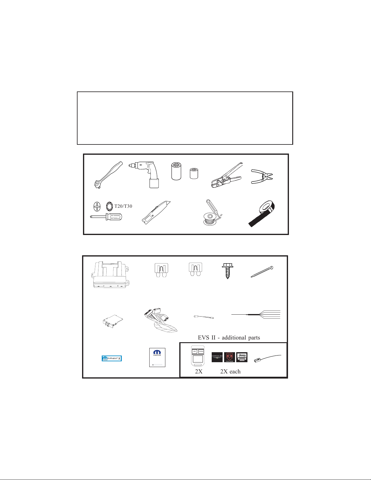
Door trigger Input Harness
(1030756)
Power Door Lock Connections - Used for EVS I only. Skip to Step I
for EVS II.
Vehicle Wire
Color
Connector/Wire
Location Door Trigger
VT/WT 20-way Brown, Pin #5 Right Front
VT 20-way Brown, Pin #3 Left Front
VT/YL 20-way Brown, Pin #6 Right Rear
VT/GY 20-way Brown, Pin #5 Left Rear
VT/OR 20-way Brown, Pin #13 Liftgate/Decklid

9
Horn Connection
K. Locate the Dk Green/Violet wire in pin
#6 of the 6-way white connector found
underneath the steering column.
Center-splice the harness Dk Green/
Violet wire into this wire, following the
center-splice procedure.
Security Module Connections
L. Connect the 24-way connector into
the PC-12 Security module. Also,
connect the antenna connector
(EVS II Systems only) on end
opposite the main harness connec-
tor.
24-Way
Antenna
LED
J. Drill 9/32” hole in trim panel as
shown in diagram. Exact place-
ment needs to be determined
before drilling. Ensure there is
nothing on the backside of the
panel and there is enough depth for
the LED when the panel is re-
placed. Do not install LED into
panel yet. Route 2-pin harness
from main wire harness to LED and
mate connectors. Use LED in this
configuration during system
programming. Install the LED into
the panel when reassembling the
dash.
Note: After connecting all connections through step I, replace the cluster
(4 screws) and then proceed to step J.

10
Option Programming.
The remote security system has several installer programmable options which
can be changed to accomodate different circumstances. In most cases, there
will be a need to change option settings (i.e. adjustment of shock sensor
sensitivity, horn pulse output duration, etc).
A. Open the driver’s door.
B. Turn the ignition to the “on” position.
C. Press and hold the programming/override button; After 10 seconds the
parking lights will flash 3 times indicating the system is now in learn
mode.
D. Release the programming button.
E. Press and release the programming button once more; The parking
lights will flash 4 times indicating the system has entered Option Bank 1.
System Programming
Notes:
1. Reconnect the negative battery terminal prior to programming.
2. EVS I System installation requires 2 working factory RKE keyfobs for
programming options & Driver’s Door Priority Unlock feature to be
enabled for proper operation of the security system. Refer to vehicle’s
Service Manual.
3. This system has 2 option banks. Bank 1 has 8 options, and Bank 2
has 4 options. Refer to the Option Bank Chart on page 13 for details.
To change the setting of an option: (EVS I Systems only)
A. Press the door trim “Lock” switch or, if the vehicle’s door lock feature is
non-functional with the ignition turned on, press the factory keyfob
“Lock” button (of the keyfob that is not in the ignition cylinder) to advance
to the desired option (refer to the Option Bank Chart).
The parking lights will flash a number of times indicating which option
is selected (i.e. Two flashes indicates that option number two has been
selected).
B. Press the door trim “Unlock” switch to change the setting of an option..
The status LED indicates the setting of the option; LED ON indicates
that the option is on, LED OFF indicates that the option is off.
C. To advance to Option Bank 2, at any point while in Option Bank 1, press
and release the programming/override button to advance to option bank
number two. The parking lights will flash 5 times indicating the system
has entered Option Bank 2.
To return back to Option Bank 1, press and release the programming/
override button once again (4 flashes).

11
Shock sensor setting: (EVS I Systems only)
(Ensure module is mounted before adjustment!)
The “Lite-touch” and “Full shock” sensor settings are always the first and
second options, respectively, in Option Bank 1. To change the shock
sensor setting, follow these steps:
A. Make sure the driver’s window is rolled down.
B. Enter Option Learn Mode, Option Bank 1, as shown on page 10.
C. Go to option #1 for Lite-touch (parking lights flash 1 time).
D. Close all doors (wait for domelight to turn off).
E. Press the door trim “Unlock” switch to increase sensitivity and press the
door trim “Lock” switch to decrease sensitivity.
F. Test the shock sensor sensitivity (while in option learn mode) by
applying an impact with an open hand to the windshield. Caution -
make sure to remove articles of jewelry to avoid scratching or
breaking glass.
The parking lights will flash each time an impact is detected that is
greater than the current setting.
G. Once the desired Lite-touch sensitivity is achieved, open a door to
advance to the Full shock option by pressing the door trim “Lock” switch
or, if the vehicle’s door lock feature is non-functional with the ignition
turned on, press the factory keyfob “Lock” button (parking lights flash 2
times). Repeat steps D through F to set Full shock sensitivity.
H. Open a door to continue with “To change the setting of an option” on
page 10 (if necessary).

12
To change the setting of an option: (for EVS II Systems only)
A. Enter Option Learn Mode, Option Bank 1, as shown on page 10.
B. Press both “Arm” & “Disarm” buttons together to advance to the desired
option (refer to the Option Bank Chart).
The parking lights will flash a number of times indicating which option is
selected (i.e. Two flashes indicates that option number two has been
selected).
C. Press the “Arm” button to change the setting of an option..
The status LED indicates the setting of the option; LED ON indicates that
the option is on, LED OFF indicates that the option is off.
D. To advance to Option Bank 2, at any point while in Option Bank 1, press
and release the programming/override button to advance to option bank
number two. The parking lights will flash 5 times indicating the system
has entered Option Bank 2.
To return back to Option Bank 1, press and release the programming/
override button once again (4 flashes).
Shock sensor setting: (EVS II Systems only)
(Ensure module is mounted before adjustment!)
The “Lite-touch” and “Full shock” sensor settings are always the first and
second options, respectively, in Option Bank 1. To change the shock sensor
setting, follow these steps:
A. Make sure the driver’s window is rolled down.
B. Enter Option Learn Mode, Option Bank 1, as shown on page 10.
C. Press “ARM” & “DISARM” buttons together to go to option #1 for Lite-
touch (parking lights flash 1 time).
D. Press the “ARM” button to increase sensitivity and press the “DISARM”
button to decrease sensitivity.
E. Test the shock sensor sensitivity (while in option learn mode) by applying
an impact with an open hand to the windshield. Caution - make sure to
remove articles of jewelry to avoid scratching or breaking glass.
The parking lights will flash each time an impact is detected that is
greater than the current setting.
F. Once the desired Lite-touch sensitivity is achieved, press “ARM” &
“DISARM” buttons together to advance to option #2 for Full shock
(parking lights flash 2 times). Repeat steps D through Eto set Full shock
sensitivity.
G. Press “ARM” & “DISARM” buttons together to advance to the next
option (if necessary).

13
Option Bank 1 – 4 flashes
1 – Lite-touch adjustment
2 – Full shock adjustment
3 – Horn pulse short/long*
On - Short output, Off - Long output...............................................................................On
4 – Selectable chirps
Enables arming/disarming confirmation chirps.........................................................On
5 – Silent choice................................................................................................................On
On – Confirmation chirp on second press of transmitter button
Off – Confirmation chirp on first press of transmitter button.
Requires option #4(above) to be ON............................................................................On
6 – Not used
7 – Optional alarm disable
Disables security functionality........................................................................................Off
8 – Noise control
Limits alarm trips to 5 per zone.....................................................................................On
Option Bank 2 – 5 flashes
1 – Door ajar switch input polarity
LED On – Positive, LED Off – Negative........................................................................Off
2 – Unlock switch sense input polarity
LED On – Positive, LED Off – Negative........................................................................On
3 - Not used
4 – Door ajar input entry delay
(5) Five Second entry delay. ...........................................................................................Off
FACTORY SETTING
FACTORY SETTING
Option Programming - Option Banks
*If the horn does not honk when the systems is triggered, turn off Option #3 in
Option Bank #1.

14
Dash reassembly.
A. Reverse the dash dissassembly procedure.
Reassembly
Component mounting.
A. Mount security module to existing underdash braces or wire harnesses
using the supplied wire ties. Avoid moving parts (steering column, brake
pedal assembly).
B. Using supplied wire ties, secure the security module harness to existing
wire harnesses under the left side of the dash. Ensure no wires will become
entangled in the steering column knuckle and that they are not visible to
vehicle occupants.
C. Using a supplied wire tie, secure the programming/override button to the
harness leading to the vehicle’s diagnostic connec-
tor. Consistency in mounting this switch in the
same place every time will make it easier to find in
case the system comes back for service. Also,
the dash will not have to be disassembled to ac-
cess it. Ensure that the placement of the pro-
gramming/override button is indicated in the
Owner’s manual and the customer knows
where it is located and can access it..
SECURITYSYSTEMARM / DISARM
USING FACTORY RKE KEYFOBS
VERIFY INTERIOR DOOR TRIM UNLOCK SWITCH DOES NOT DISARM SYSTEM
ALL ENTRYPOINTS TRIPALARM CYCLE
STATUS INDICATOR FLASHESWHENARMED
SHOCK SENSOR SETTINGS (LITE-TOUCH & FULL SHOCK)
Security Function Checklist
PROGAMMING/OVERRIDE BUTTON DISARMS SYSTEM WITH IGNITION ON

15
PROGRAMMING/
OVERRIDE BUTTON
FACTORY
IGNITION
HARNESS
MALE
IGNITION SWITCH
CONNECTOR
FEMALE
IGNITION SWITCH
CONNECTOR
05140464AA
PC-12 MODULE
SECURITY DNA
LED
GROUND
FACTORY
HARNESS
PARKING LIGHT CONNECTION:
26-WAY WHITE CONNECTOR
LOWER LEFT KICK PANEL
White/Violet Pin #12
CHRYSLER PT CRUISER SECURITY SYSTEM LAYOUT
Harness Yellow to
LT BLUE (ARM)
BROWN (DISARM)
LT GREEN (UNLOCK SENSE)
WHITE
(DOOR TRIGGER)
To Tan/Dk Blue Pin #9
10-way Black connector
To Tan/Dk Green Pin #5
10-way Black connector
To Tan/White Pin #7
10-way Black connector
Right Rear
To Violet/Yellow Pin #6
20-way Brown connector
Left Rear
To Violet/Grey Pin #5
20-way Brown connector
Liftgate/Decklid
To Violet/Orange Pin #13
20-way Brown connector
Right Front
To Violet/White Pin #11
20-way Brown connector
Left Front
To Violet Pin #3
20-way Brown connector
DOOR TRIGGER CONNECTIONS:
(using door trigger harness p/n 1030756)
All 8 connections behind dash cluster
FACTORY
HARNESS
Dk Green/Violet Pin #3
Harness Green to
HORN CONNECTION:
6-WAY WHITE CONNECTOR
BELOW STEERING COLUMN

16
INSTRUCCIONES PARALAINSTALACIÓN
Es conveniente que la instalación esté a cargo de un profesional.
Servicio Técnico
Paracomunicarse con los representantes
autorizados - (800) 34-MOPAR
Horario: Lunes a viernes de 9 a 18, Hora del Este
Sábados de 10 a 14, Hora del Este
1030928
REV.A
8/05 K6859682
Sistema de seguridad para
Chrysler PT Cruiser
123456789012345678901234567890121234567890123456789012345678901
1
2345678901234567890123456789012123456789012345678901234567890
1
1
2345678901234567890123456789012123456789012345678901234567890
1
1
2345678901234567890123456789012123456789012345678901234567890
1
1
2345678901234567890123456789012123456789012345678901234567890
1
1
2345678901234567890123456789012123456789012345678901234567890
1
1
2345678901234567890123456789012123456789012345678901234567890
1
1
2345678901234567890123456789012123456789012345678901234567890
1
1
2345678901234567890123456789012123456789012345678901234567890
1
1
2345678901234567890123456789012123456789012345678901234567890
1
1
2345678901234567890123456789012123456789012345678901234567890
1
1
2345678901234567890123456789012123456789012345678901234567890
1
1
2345678901234567890123456789012123456789012345678901234567890
1
123456789012345678901234567890121234567890123456789012345678901
Nota: Para las instalaciones de EVS I, son necesarios los dos
llaveros para abrir las puertas a distancia provistos de fábrica y
debe estar habilitada la función que da prioridad a la puerta del
conductorparadestrabarlasdemás.

17
Este aparato cumple con la parte 15 de las normas de la Comisión Federal de Comunicaciones de
los EE.UU. (FCC) y con la norma industrial de Canadá RSS-210. El funcionamiento depende de
las dos condiciones a continuación: (1) que este aparato no provoque interferencias nocivas y
(2) que este aparato deba aceptar interferencias recibidas, como aquéllas que puedan provocar un
funcionamiento no deseado.
Este producto está fabricado en instalaciones que no dañan el ambiente y puede
contener ciertos materiales reciclados. Todos los materiales cumplen con las
especificaciones originales de calidad y confiabilidad, o las superan.
Sistema de seguridad para Chrysler PT
Cruiser
Índice
Preparación del vehículo...........................................................................19
Preparación del módulo............................................................................21
Instalación individualizada del mazo de cables......................................22
Programación del sistema.....................................................................25
Programación del EVS I.........................................................................25
Programación del EVS II........................................................................27
Tabla de los bancos de opciones..........................................................28
Pruebas al sistema..................................................................................29
Rearmado.................................................................................................29
Disposición del sistema.........................................................................30
123456789012345678901234567890121234567890123456789012345678901
1
2345678901234567890123456789012123456789012345678901234567890
1
1
2345678901234567890123456789012123456789012345678901234567890
1
1
2345678901234567890123456789012123456789012345678901234567890
1
1
2345678901234567890123456789012123456789012345678901234567890
1
1
2345678901234567890123456789012123456789012345678901234567890
1
1
2345678901234567890123456789012123456789012345678901234567890
1
1
2345678901234567890123456789012123456789012345678901234567890
1
1
2345678901234567890123456789012123456789012345678901234567890
1
1
2345678901234567890123456789012123456789012345678901234567890
1
1
2345678901234567890123456789012123456789012345678901234567890
1
1
2345678901234567890123456789012123456789012345678901234567890
1
1
2345678901234567890123456789012123456789012345678901234567890
1
123456789012345678901234567890121234567890123456789012345678901
Nota: Para las instalaciones del EVS I son necesarios los dos
llaveros para abrir las puertas a distancia provistos de fábrica y
debe estar habilitada la función que da prioridad a la puerta del
conductor para destrabar las demás.

18
PIEZAS NECESARIAS
Pieza número 82209707 (para EVS I) o 82209717 (para EVS II)
5A 1X 15A 1X 1X 5X
Owner's Manual
VehicleRemote Start System
TM
FeaturingPowerCodeTechnology
FortheUltimatein Comfort,ConvenienceandSecurity
TM
®
HERRAMIENTAS NECESARIAS
10mm 1/4”
PREPARACIÓNDELVEHÍCULO
1. Baje una o dos de las ventanas de los pasajeros por si el vehículo se cierra y las
llaves quedaran adentro.
2. Desconecte y aísle el cable negativo de la batería. Necesitará reconectar la batería
antes de la programación.
3. Para programar las opciones durante la instalación del sistema EVS I son necesarios los dos
llaveros provistos de fábrica para abrir las puertas a distancia.
TM
DOOR TRIGGER INPUT HARNESS
T-
20
1234567890123456789012345678901212
1
23456789012345678901234567890121
2
1
23456789012345678901234567890121
2
1
23456789012345678901234567890121
2
1
23456789012345678901234567890121
2
1
23456789012345678901234567890121
2
1
23456789012345678901234567890121
2
1
23456789012345678901234567890121
2
1
23456789012345678901234567890121
2
1
23456789012345678901234567890121
2
1
23456789012345678901234567890121
2
1234567890123456789012345678901212
EVS II – Otras piezas necesarias
ARM DISARM
2X 2X cada uno
1234
1
23
4
1
23
4
1234
T20/T30
MAZO DE CABLES DE ENTRADA DE LA
APERTURA AUTOMÁTICA DE LAS
PUERTAS

19
Preparación del vehículo
Quite el panel inferior del tablero, el panel
metálico, la bolsa de aire y la cubierta del
árbol de dirección, todos del lado del con-
ductor.
A. Quite el panel inferior del tablero con
una varilla de tapicería de manera de
liberar las lengüetas de enganche que
el panel tiene detrás. La parte superior
está sujeta con grampas.
Quite el panel del tablero.
B. Quite los (4) tornillos del panel inferior
metálico.
C. Quite los (3) tornillos de la cubierta del
árbol de dirección. Separe y quite la
cubierta del árbol de dirección.
D. Quite el (1) tornillo del panel izquierdo
del tablero y quite el panel. Si es
necesario, desconecte el conector.
E. Quite el (1) tornillo del panel que cubre
el grupo de instrumentos ubicado a la
izquierda del árbol de dirección.
F. Quite los (2) tornillos que ajustan los
ángulos superiores en la tapa de la bolsa
de aire.
G. Quite los (2) tornillos del módulo de la
bolsa de aire. Desconecte el conector
después de confirmar que la batería esté
desconectada.No es obligatorio quitar
la bolsa de aire pero facilita la
instalación.
Generalidades
El mazo de cables del módulo de seguridad se une con el conector del interruptor de encendido
existente, la bocina, las luces de estacionamiento, las conexiones que disparan la apertura
automática de puertas y la traba eléctrica, y un terminal de tierra.

20
Preparación del vehículo - continuación
H. Quite el zócalo izquierdo. El panel está
sujeto con grampas.
I. Quite los (2) tornillos del visor del lado del
conductor. Desconecte el conector y quite
el visor.
J. Quite el (1) tornillo de la sujeción del visor.
K. Quite suavemente el parante A del conduc-
tor.
L. Mientras empuja hacia arriba suavemente
el tablero del lado del conductor, quite la
tapa del grupo de instrumentos.
M. Quite los (4) tornillos del grupo de
instrumentos.
N. Desconecte los (4) conectores del
grupo de instrumentos y con
cuidado quite el grupo de
instrumentos.
Table of contents
Languages:
Other Mopar Security System manuals