Moravian Instruments DataLab PC series User manual

DataLab PC
Industrial PC-compatible computer
(models DataLab PC 1200,DataLab PC 1000,
DataLab PC 800,DataLab PC 610,DataLab PC 600)

All information furnished by Moravian Instruments is believed to be accurate. Mora-
vian Instruments reserves the right to change any information contained herein without
notice.
DataLab devices are not authorized for and should not be used within Life Support Sys-
tems without the specific written consent of the Moravian Instruments. Product warranty
is limited to replacement of defective components and does not cover injury or property
or other consequential damages.
This document may be copied when keeping to the following conditions:
•The whole text must be copied without modifications and must contain all pages.
•All notifications of this kind must be mentioned in the documentation.
Copyright © 2004–2006, Moravian Instruments
Moravian Instruments
Masarykova 1148
763 02 Zlín
Czech Republic
tel./fax: 577 107 171
internet: www.mii.cz
mail: [email protected]

Contents
Introduction ................................. 5
Technicalspecifications ........................... 7
DataLab PC configurations .......................... 9
DataLab PC 1200 9
DataLab PC 1000 10
DataLab PC 800 11
DataLab PC 610 12
DataLab PC 600 13
Differences among DataLab PC configurations 14
Optional components 14
RAM memory 14
HDD and CF card 14
Operating system 15
Windows XP Embedded (XPe) 15
Writing data to CF card in Windows XP Embedded 16
Connectorplacement ............................ 17
ATX panel 17
Power supply and auxiliary circuits 17
Power supply connector and main switch 18
Auxiliary 12 V DC power output 18
Indication LEDs 18
Reset 18
Communicationlines ............................ 19
RS-485 19
RS-485 settings 19
Jumper settings 19
Watchdog .................................. 21
Jumpersettings ............................... 22
Mounting .................................. 23
Maintenance ................................ 24
CMOS RAM backup battery 24

4

5
Introduction
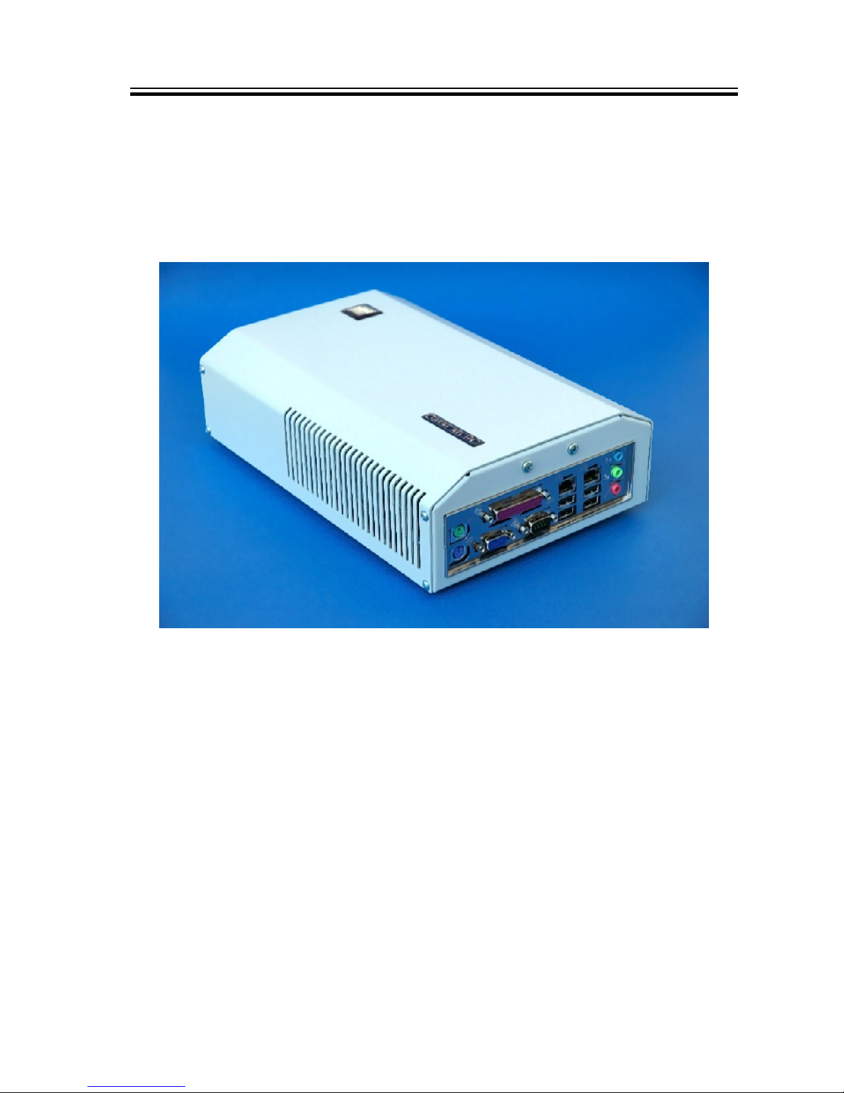
DataLab PC is a new line of compact computers fully compatible with PC standard, but
designed to work in industrial applications, laboratories and schools. They employ low-
power VIA EDEN processors, which enable working without active (fan assisted) cooling
of CPU and chipset. This ensures durability and reliable operation required in industrial
applications. On the other side the compatibility with the PC standard (VIA EDEN proces-
sors are fully compatible with x86 architecture) relatively high performance, rich set of
interfaces, communication capabilities and low price bring numerous advantages.
•Full compatibility with PC standard allows running of numerous operating systems
(Windows 2000, Windows XP, Linux), including systems designed for embedded appli-
cations (Windows CE, Windows XP Embedded, Embedded Linux).
•Small, compact and robust case protects the computer against mechanical damage
and allows easy manipulation. DataLab PC can be easily mounted on standard DIN
rail.
•Low power consumptions of CPUs (CPU and chipset heat sinks are passive, without
fans) ensures long durability without maintenance.
•High performance and large memory (it is possible to plug 64 MB up to 512 MB or
1 GB memory module to standard DIMM slot) enables running of big and demanding
application.
•Users can choose between standard 2.5" IDE hard drive or Compact Flash (CF) memory
card (it is necessary to use embedded OS like Windows XPe to use CF card instead of
HDD). Ability to work without hard drive adds to the overall reliability of the whole
computer.
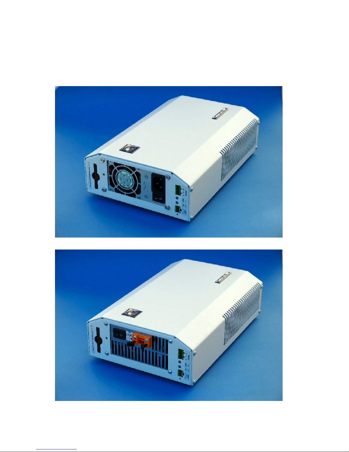
•There are DataLab PC variants with standard 230 V/50 Hz AC power supply as well as
DC power supplies.

6
•Presence of all standard PC interfaces (RS-232C, LPT, Ethernet, USB 1.1 and 2.0, VGA,
PS/2 keyboard and mouse, Audio) on the standard ATX panel makes DataLab PC as
flexible as standard desktop PCs.
•The DataLab PC incorporates hardware USB-based watchdog. The watchdog driver in
the forms of Windows DLL, Active X component and Control Web driver is supplied
with every computer.
•DataLab PC computers are ideally suited to run Control Web process control software.

7
Technical specifications
Power supplies
power line 230 V/50 Hz AC 11–20 V DC 18–28 V DC
supply 200 W ATX 80 W ATX-DC 120 W ATX-DC
Maximum AC power consumption
0.2 A at 230 V
Motherboard
Mini-iTX standard
Auxiliary DC output power supply
12 V / 500 mA DC, common ground
Mounting
Wall mounting on standard 32 mm DIN-rail
table-top case
Weight
max. 3.5 kg
278
76,5
186
DataLab PC
Figure 1 DataLab PC case dimensions

8
KBD
MOUSE
VGA
USB
ETH
RS-232C
LPT AUDIO
I
O
RS-485 +12 V DC
Compact Flash Card
Figure 2 Front panels
Remark 1 Front panel connector placement can differ according to DataLab PC type.

9
DataLab PC configurations
DataLab PC is offered in several models differing in CPU speed, memory types and avail-
able ports. Other features are available for all models and are configurable according to
customer’s needs.
DataLab PC 1200
•CPU VIA Eden 1.2 GHz (x86 compatible)
•512 MB DDR2, 533 MHz SDRAM1, shared video memory
•230 V AC or 18–28 V DC and 11–20 V DC power supplies available, +12 V DC output
available for powering of peripherals
•typical power consumption (without HDD) 15 W
•watchdog
•interfaces:
— analog VGA output
— PS/2 (mini DIN) keyboard and mouse
— 1× RS-232C (COM1)
— 1× RS-4852
— 1× Gigabit Ethernet
— 4× USB 2.0
— audio In/Out
— Compact Flash Type 1 memory card slot
— optional 40 GB Hard Disk Drive3
One DIMM slot is available, memory size can be from 64 MB to 1 GB
1
RS-485 module is optional component and must be ordered separately
2
any 2,5" disk with ATA or SATA interface can be used
3

10
DataLab PC 1000
•CPU VIA C7 1 GHz (x86 compatible)
•512 MB DDR2, 533 MHz SDRAM4, shared video memory
•230 V AC or 18–28 V DC and 11–20 V DC power supplies available, +12 V DC output
available for powering of peripherals
•typical power consumption (without HDD) 15 W
•watchdog
•interfaces:
— analog VGA output
— PS/2 (mini DIN) keyboard and mouse
— 1× RS-232C (COM1)
— 1× 10/100 Mbps Ethernet
— 4× USB 2.0
— audio In/Out
— Compact Flash Type 1 memory card slot
— optional 40 GB Hard Disk Drive5
One DIMM slot is available, memory size can be from 64 MB to 1 GB
4
any 2,5" disk with ATA or SATA interface can be used
5

11
DataLab PC 800
•CPU VIA Eden 800 MHz (x86 compatible)
•256 MB DDR400 SDRAM6, shared video memory
•230 V AC or 18–28 V DC and 11–20 V DC power supplies available, +12 V DC output
available for powering of peripherals
•typical power consumption (without HDD) 19 W
•watchdog
•interfaces:
— analog VGA output
— PS/2 (mini DIN) keyboard and mouse
— 1× RS-232C (COM1)
— 1× RS-4857
— 1× 10/100 Mbps Ethernet
— 2× USB 2.0
— audio In/Out
— Compact Flash Type 1 memory card slot
— optional 40 GB Hard Disk Drive8
One DIMM slot is available, memory size can be from 64 MB to 1 GB
6
RS-485 module is optional component and must be ordered separately
7
any 2,5" disk with ATA or SATA interface can be used
8

12
DataLab PC 610
•CPU VIA Eden 600 MHz (x86 compatible)
•256 MB DDR266 SDRAM9, shared video memory
•230 V AC or 18–28 V DC and 11–20 V DC power supplies available, +12 V DC output
available for powering of peripherals
•typical power consumption (without HDD) 15 W
•watchdog
•interfaces:
— analog VGA output
— PS/2 (mini DIN) keyboard and mouse
— 1× RS-232C (COM1)
— 1× RS-48510
— 2× 10/100 Mbps Ethernet
— 4× USB 2.0
— 1× Parallel port (LPT)
— audio In/Out
— Compact Flash Type 1 memory card slot
— optional 40 GB Hard Disk Drive11
One DIMM slot is available, memory size can be from 64 MB to 1 GB
9
RS-485 module is optional component and must be ordered separately
10
any 2,5" disk with ATA interface can be used
11

13
DataLab PC 600
•CPU VIA Eden 600 MHz (x86 compatible)
•256 MB DDR266 SDRAM12, shared video memory
•230 V AC or 18–28 V DC and 11–20 V DC power supplies available, +12 V DC output
available for powering of peripherals
•typical power consumption (without HDD) 15 W
•watchdog
•interfaces:
— analog VGA output
— PS/2 (mini DIN) keyboard and mouse
— 1× RS-232C (COM1)
— 1× RS-48513
— 1× 10/100 Mbps Ethernet
— 2× USB 2.0
— 1× Parallel port (LPT)
— audio In/Out
— video Out
— Compact Flash Type 1 memory card slot
— optional 40 GB Hard Disk Drive14
One DIMM slot is available, memory size can be from 64 MB to 1 GB
12
RS-485 module is optional component and must be ordered separately
13
any 2,5" disk with ATA interface can be used
14

14
Differences among DataLab PC configurations
The following table summarizes differences among various DataLab PC configurations.
interface Ethernet USB 2.0 RS-485 CPU memory SDRAM
DataLab PC 1200 1×1 Gbps 4× optional 1,2 GHz DDR2, 533 MHz
DataLab PC 1000 1×10/100 Mbps 4× no 1 GHz DDR2, 533 MHz
DataLab PC 800 1×10/100 Mbps 2× optional 800 MHz DDR, 400 MHz
DataLab PC 610 2×10/100 Mbps 4× optional 600 MHz DDR, 266 MHz
DataLab PC 600 1×10/100 Mbps 2× optional 600 MHz DDR, 266 MHz
Optional components
RAM memory
Standard DIMM memory modules are used. Memory capacity can be chosen according
to the current memory modules availability.
HDD and CF card
Standard 2.5" IDE HDD is optional.
The DataLab PC contains one slot for Type 1 CF card. CF card are connected directly
to IDE bus so it must work in “True IDE” mode. It is possible to use CF card with or
without HDD. The embedded operating system can boot from CF (Windows XP Embedded
or Windows CE).
The Windows XP Embedded operating system protects CF card against writes with so-
called “write filter”. So it can be useful to combine CF card with another IDE Flash
disk connected to another (internal) IDE port. IDE Flash disk can be used e.g. to store
Control Web archive files etc. Data are written directly to IDE Flash disk as opposite to
CF card, where all writes are accumulated in RAM buffers and these buffers are physi-
cally committed to CF card upon executing of explicit command (see chapter Operating
system).
CF card works as IDE master on secondary IDE channel by default. Master or slave mode
can be selected by jumper J1 on the CF slot printed circuit board. This board is accessible
after removing the computer cover.
Warning 1
It is possible to manipulate with CF card only when DataLab PC is turned off!

15
Operating system
DataLab PC works with all operating systems compatible with standard PC architecture.
User can choose whatever operating system he/she wants to use:
•Windows CE.NET15
•Windows XP Embedded15
•Windows 200016
•Windows XP Professional16
Windows XP Embedded (XPe)
Windows NT family of operating systems (including Windows 2000 and Windows XP) are
traditionally linked with the PC architecture. Many properties of Windows NT represent
no problem for desktop PCs or servers (or, on the contrary, may be advantageous), but
practically disable implementation of embedded applications—Windows NT needs a hard
disk for the paging file, the installation is quite wide, users have restricted possibilities to
influence the configuration of the system, etc. However, for example, the hard disk is not
accessible in many solutions due to its sensitivity to mechanical shocks and restricted
time of non-stop operation.
Despite this fact there are series of embedded applications for which the further prop-
erties of Windows are very welcome—in particular, very rich support of the most varied
hardware, availability of development tools and a large number of ready programs, etc.
If there is some peripheral to be connected to a PC on the market today, the chance
that it will be accompanied by the driver for Windows 2000/XP is really very high. Of
course, it also concerns equipment for industrial automation when producers supply sup-
porting libraries for communication with its hardware, OPC servers and other software,
mainly for Windows 2000/XP. Another welcome property of Windows 2000/XP is robust-
ness. Although in no case is it a real-time operating system, for permanent running of
applications and processing of a large volume of data this system is very suitable.
The first attempt at modification of Windows NT for use in embedded solutions was the
creation of the Windows NT Workstation 4.0 Embedded. The basis of the modifications
was mainly isolation of individual modules of the system core so as to be able to work
relatively independently. The distribution included a development tool which enabled
OEM partners to configure the system—i.e. to include modules, which are necessary for
the respective application and to omit components, which were useless. In this manner
it was possible to create images of Windows NT, e.g., without a graphic user interface,
without the support of network communication, etc. A very important property was the
ability to work without hard disk, i.e. only from, e.g,. CompactFlash cards.
Remark 2 Memory media based on FLASH memories have a great disadvantage compared
with hard disks—the number of recording cycles is restricted according to the type of
memory to 100,000 to 1,000,000. But there are a series of recordings on the disk during
the work of the operating system and applications—auxiliary files are created and deleted,
events are recorded into log files, etc. Mainly, there are frequent writes into the page file).
The attempt to install the standard Windows NT on FLASH disk may result in success, but
the life time of such an installation can be only several weeks or months. Then FLASH will
start to fail and the system will stop functioning.
Requires Compact Flash card.
15
Requires hard drive.
16

16
For systems used for implementation into embedded solutions (Windows CE) there is no
such problem, systems do not write on the disk during work and if they need to write some-
thing, it is possible to create a virtual disk in RAM. Systems adapted for work in embedded
applications (Windows NT/XP Embedded) are equipped with a so-called write filter, which
is a component able to catch attempts to write to the hard disk and to prevent damaging
the FLASH memory. Ability to work without the page file is part of the modifications of the
system.
Although Windows NT Workstation 4.0 Embedded can be used in embedded solutions,
it was introduced on to the market just before the introduction of Windows 2000 on PC
and servers. Work on Windows 2000 Embedded started, but it was not introduced on to
the market. The final introduction was the version Windows XP Embedded (also called
Windows XPe).
Windows XPe (like Windows CE) is not sold as a product for end users. Only original
equipment manufacturers (OEM) may purchase development tools and create installation
Windows XPe for their equipment. There is a wide database of device drivers (graphic
adapters, network cards, printers, . . .) available. At the same time, there is available a
write filter for installation of the system on FLASH disks or for creation of a bootable
image of the system on CD-ROM (of course, Windows XPe may work from a standard hard
disk or boot the system from the network).
Writing data to CF card in Windows XP Embedded
When the Windows XPe operating system is installed on CF card, all writes to CF card
are stored to RAM buffer instead of directly to the CF card to protect the CF card from
“wearing off” (number of writes is limited to approx. 1 million). RAM buffers are physically
transferred to the CF card upon execution of the ewfmgr command.
DataLab PC with Windows XPe pre-installed are supplied with a shortcut on the desktop,
which executes command ewfmgr c : -commit. All data stored in RAM buffers are
passed to the file system to be written to the CF. However, keep in mind that the actual
write is performed during correct system shutdown or reboot. Simply switching the
computer off discards all writes.
It is necessary to keep this on mind when designing the embedded application and
when choosing the software platform and used utilities etc. Frequent stores should be
performed e.g. on remote disk storage. Another possibility is to use separate IDE Flash
disk or HDD for storing files. The CF card can be used for occasional writes (configuration
data etc.) without problems, just every change must be explicitly committed.
DataLab PC equipped with CF card can be switched off anytime without the risk of
corrupting the operating system or application files.

17
Connector placement
There is a standard ATX connector panel on one side of the DataLab PC. The power supply
connectors and main switch, as well as CF slot, 12 V DC auxiliary output and possible RS-
485 interface connector are placed on the opposite side.
ATX panel
Connector placement on ATX panel depends on individual configuration. Panel picture
is shown in individual configuration descriptions. Thorough description can be found in
respective motherboard documentation, supplied with every computer.
Power supply and auxiliary circuits
I
O
RS-485
L1
L2
230 V AC
Main switch
Auxiliary power supply
+12 V
DC
Compact Flash Card
Figure 3 Power supply connectors
USB watchdog, auxiliary power supply, indication LEDs and RS-485 interface are placed
on the separate PWD printed circuit board. This board is accessible after removing the
computer cover.
Figure 4 PWR printed circuit board

18
Power supply connector and main switch
Depending on the power supply, the DataLab PC has either standard 230 V AC power
plug or two-pole connector for DC power supply. Both power supply variants have main
switch.
Auxiliary 12 V DC power output
Two-pole connector with 12 V DC auxiliary power output is available on the side of the
DataLab PC computer. Maximal output current is 500 mA.
Warning 2
Take care to use proper polarity of the auxiliary power output.
Indication LEDs
There are two two-colors LED on the side of the DataLab PC computer:
•LED 1 indicates RS-485 communication line state.
•LED 2 indicates the DataLab PC powered state and also indicates auxiliary power
output overload.
LED 1 states:
green light RS-485 transmits
red light RS-485 receives
LED 2 states:
no light main power off
green light power on
red light 800 mA maximal output current of 12 V DC exceeded
Reset
There is no reset button on DataLab PC. It is possible to reboot it either by software
(choose Windows Shutdown/Reset) or by switching the computer off and then on again.
Warning 3
When the DataLab PC was switched off, wait a couple of seconds before switching on
again.

19
Communication lines
Every DataLab PC is equipped with standard RS-232C serial line, USB ports and Ethernet
interface. DataLab PC 800 and DataLab PC 600 contain 2 USB ports, DataLab PC 1200,
DataLab PC 1000 and DataLab PC 610 offers 4 USB ports on ATX panel.
DataLab PC 1200,DataLab PC 800,DataLab PC 610 and DataLab PC 600 can be also equipped
with isolated RS-485 serial interface. RS-485 module is optional and must be ordered sep-
arately. The RS-485 is connected to internal serial interface so the RS-232C interface on
the ATX panel remain free for other usage.
RS-485
The RS-485 serial line uses three-pole connector. Communication line is isolated. Two-
colors LED 1 indicates communication: green light—transmission, red light—receiving.
ABGND
RS-485
+
12 V DC L1 L2
Figure 5 Auxiliary 12 V DC
output and RS-485 connectors
RS-485 settings
The printed circuit board is accessible after removing the computer cover. RS-485 inter-
face module is plugged (piggybacked) to PWR board, which contains connectors.
Jumper settings
•J1—controls direction control. Direction can be controlled according to RTS signal or
automatically depending on the transmitter activity. Automatic direction control re-
quires setting of time delays according to the communication speed by the RT resistor.
Automatic direction control (default)
RTS-controlled direction
•RT—defines time delay of automatic direction control. The 68 kΩ resistor is used by
default. The RT value can be calculated from the equation τ[ms] = 7 × RT [MΩ], where
τis a time constant. For instance for the speed 19,200 Bd with 1 start bit, 8 data bits,
1 stop bit and 1 parity bit time constant is: 11 bits / 19,200 bps = 0.573 ms; which
corresponds to RT = 81 kΩ.
•RA, RB, RC—terminating resistors. 360 Ω resistors are used by default.

20
Remark 3 If there is an RS-485 module marked GPA used, then the direction is controlled
automatically and neither J1 jumper nor RT resistor have any meaning.
This manual suits for next models
5
Table of contents