Morehouse UCM Guide

ISO/IEC 17025 / ANSI/NCSLI Z540.3 Accredited
Morehouse Instrument Company, Inc.
1742 Sixth Ave., York, PA 17403-2675 USA
P: (717) 843-0081
F: (717) 846-4193
info@mhforce.com
www.mhforce.com
PM-5201
Rev. 11/2021
Operation and Instruction Manual
Universal Calibrating Machine (UCM)

Universal Calibrang Machine
(UCM) Manual
(PM-5201)
Morehouse Instrument Company, Inc.
1742 Sixth Ave., York, PA 17403-2675 USA
Phone: (717) 843-0081
www.mhforce.com
Page 2
Rev. 11/2021
Table of Contents
1.Introducon
1.1 Origin and Use ...........................................................................4
1.2 Funconal Operaon......................................................................4
1.3 Design ..................................................................................5
1.4 Reference Standard .......................................................................5
1.5 Overview ...............................................................................6
2. Descripon
2.1 General .................................................................................7
2.2 Construcon.............................................................................7
2.3 Hydraulic Jack Assembly . . . . . . . . . . . . . . . . . . . . . . . . . . . . . . . . . . . . . . . . . . . . . . . . . . . . . . . . . . . . . . . . . . . 9
2.4 Loading Power Supply .....................................................................9
3. Preparaon for Use
3.1 Unpacking..............................................................................13
3.2 Installaon .............................................................................13
3.3 Installaon of a Reference Standard ........................................................14
3.4 Preparing the Hand Pump for Use . . . . . . . . . . . . . . . . . . . . . . . . . . . . . . . . . . . . . . . . . . . . . . . . . . . . . . . . . . 16
3.5 Preparing the Jack Assembly for Use ........................................................16
4. Operaon
4.1 Operang Condions ....................................................................17
4.2 Compression Setup ......................................................................18
4.3 Tension Setup...........................................................................21
4.4 Hand Pump Operaon....................................................................23
4.5 Universal Hydraulic Pump .................................................................24
4.6 Calibraon .............................................................................24
4.7 Tare Load ..............................................................................25
5. Service, Inspecon, Maintenance, & Lubricaon
5.1 Tools ..................................................................................27
5.2 Service Inspecon .......................................................................27
5.3 Maintenance ...........................................................................27
5.4 Lubricaon .............................................................................28
5.5 Rust Prevenon .........................................................................28

Universal Calibrang Machine
(UCM) Manual
(PM-5201)
Morehouse Instrument Company, Inc.
1742 Sixth Ave., York, PA 17403-2675 USA
Phone: (717) 843-0081
www.mhforce.com
Page 3
Rev. 11/2021
Table of Contents
6. Disassembly, Repair, and Reassembly
6.1 Disassembly and Reassembly ..............................................................29
6.2 Air Bleed Procedure for Hydraulic Jack ......................................................29
6.3 Service Instrucons for Hydraulic Hand Pump ................................................30
6.4 Repair .................................................................................30
6.5 Drawings & Parts Lists ....................................................................31
7. Accessories & Adapters for use with Morehouse Universal Calibrang Machines......................34

Universal Calibrang Machine
(UCM) Manual
(PM-5201)
Morehouse Instrument Company, Inc.
1742 Sixth Ave., York, PA 17403-2675 USA
Phone: (717) 843-0081
www.mhforce.com
Page 4
Rev. 11/2021
1. Introducon
1.1 Origin and Use
Morehouse Universal Calibrang Machines were originally developed to make use of the inherent high accura-
cy of Morehouse Proving Rings to calibrate working load cells. Today, calibrang machines are used extensively
in industrial, government, and military laboratories not only for the calibraon of load cells, but for calibrang
force transducers, dynamometers, load rings, force links, and other force measurement devices.
1.2 Funconal Operaon
The Morehouse Universal Calibrang Machine is a device for simultaneously applying a force to a high accu-
racy calibraon reference standard, and the device to be calibrated (unit under test). The force is produced by
a hydraulic jack acvated by a manually operated pump, specially designed to perform precise and accurate
calibraon work. The calibrang machine is used to calibrate compression type and tension type instruments.
The calibraon reference standard is always loaded in compression, even when calibrang an instrument in
tension.
Figure 1: Morehouse Universal Calibrating Machine 1,000,000 lbf Capacity

Universal Calibrang Machine
(UCM) Manual
(PM-5201)
Morehouse Instrument Company, Inc.
1742 Sixth Ave., York, PA 17403-2675 USA
Phone: (717) 843-0081
www.mhforce.com
Page 5
Rev. 11/2021
1.3 Design
The design of the machine has one purpose, ulmate accuracy. The force produced by the calibrang machine
is transferred directly to the unit under test without any machine loss or mechanical interference. Fricon
between the reference standard and the unit under test has been eliminated. This is essenal because even
slight fricon, which is inherent in other types of calibrang machines, frequently results in gross inaccuracies.
Non-axial loading, another factor contribung to inaccurate calibraon, is also eliminated by the design of the
machine and its accessories.
1.4 Reference Standard
While a reference standard, such as a load cell, is essenal to the funcon of calibraon, it is not supplied as
part of the Universal Calibrang Machine. Only compression reference standards need to be purchased for use
with the machine because whether performing a tension or compression calibraon, the reference standard
is always loaded in compression. Since compression reference standards are less expensive than dual mode
tension and compression type standards, the cost of reference standards for use with a Morehouse Universal
Calibrang Machines is less than for other types of machines.
Figure 2: Morehouse Ultra-Precision Load Cell

Universal Calibrang Machine
(UCM) Manual
(PM-5201)
Morehouse Instrument Company, Inc.
1742 Sixth Ave., York, PA 17403-2675 USA
Phone: (717) 843-0081
www.mhforce.com
Page 6
Rev. 11/2021
Figure 3: Morehouse Universal Calibrating Machine 100,000 lbf (500 kN) Capacity
(with motorized adjustable yoke platen)
1.5 Overview
This manual contains instrucons for the installaon, operaon, service, and roune maintenance of all More-
house Universal Calibrang Machines, regardless of capacity. If there are any quesons about the use or main-
tenance of the calibrang machine, please contact us.
Hand Pump Assembly
Stationary Frame Assembly
Adjustable Foot
Hydraulic Jack Assembly
Motorized Positioning Mechanism
Moveable Yoke Assembly
Lower Yoke Platen
Upper Yoke Platen
Drive Mechanism Housing
Tension Tie Bar
Tie Bar Locking Collar
Upper Machine Platen
Reference Standard Load Cell
Set Screw
Lower Machine Platen
Momentary Positioning Switch
Hydraulic Screw Pump
Unit Under Test in Tension

Universal Calibrang Machine
(UCM) Manual
(PM-5201)
Morehouse Instrument Company, Inc.
1742 Sixth Ave., York, PA 17403-2675 USA
Phone: (717) 843-0081
www.mhforce.com
Page 7
Rev. 11/2021
2.1 General
The Morehouse Universal Calibrang Machine is comprised of three principal assemblies, which are described
in this secon:
1- Loading Frame
2- Hydraulic Jack
3- Loading Power Supply
2.2 Construcon
Overall construcon of the calibrang machine is illustrated by the outline drawing shown in Figure 4. Dimen-
sions are indicated for the various standard capacity machines in Table 1 and 2.
2. Descripon

Universal Calibrang Machine
(UCM) Manual
(PM-5201)
Morehouse Instrument Company, Inc.
1742 Sixth Ave., York, PA 17403-2675 USA
Phone: (717) 843-0081
www.mhforce.com
Page 8
Rev. 11/2021
1 Model designaons xy are dened as:
• x = M for manual or A for automated
• y = D for domesc or E for export
2 Referenced dimensions are congured with the use of Morehouse load cells as the standards.
“A”
Max
Height
“L Max”
“L Min”
Compression
Area
Travel
Adjustment
“M Max”
“M Min”
Tension Area
Travel Adjustment
Capacity
required
(lbf)
Model
designation1
Max
capacity
A L Max2L Min2M Max2M Min2Size
10,000 UCM-11xy-01 11,500 TBD TBD TBD TBD TBD Standard
10,000 UCM-11xy-02 11,500 48.0 13.5 2.0 12.5 1.5 Compact
30,000 UCM-30xy-01 30,000 96.0 22.0 3.0 43.5 24.5 Standard
30,000 UCM-30xy-02 30,000 75.0 22.0 3.0 22.5 3.0 Compact
60,000 UCM-60xy-01 60,000 105.0 22.5 3.0 46.0 26.5 Standard
60,000 UCM-60xy-02 60,000 81.0 23.5 3.0 22.5 2.0 Compact
100,000 UCM-112xy-01 112,500 112.5 24.0 3.0 46.5 25.5 Standard
100,000 UCM-112xy-02 112,500 92.0 24.5 3.0 26.5 5.0 Compact
200,000 UCM-225xy-01 225,000 120.0 28.5 7.0 36.5 14.5 Standard
300,000 UCM-338xy-01 338,000 132.0 29.5 8.0 41.5 19.5 Standard
500,000 UCM-675xy-01 675,000 158.0 34.5 10.0 50.5 26.0 Standard
600,000 UCM-675xy-01 675,000 158.0 34.5 10.0 50.5 26.0 Standard
1,000,000 UCM-1125xy-01 1,125,000 192.5 40.0 11.0 54.0 25.0 Standard
Table 1: UCM lbf Dimensions (inches)
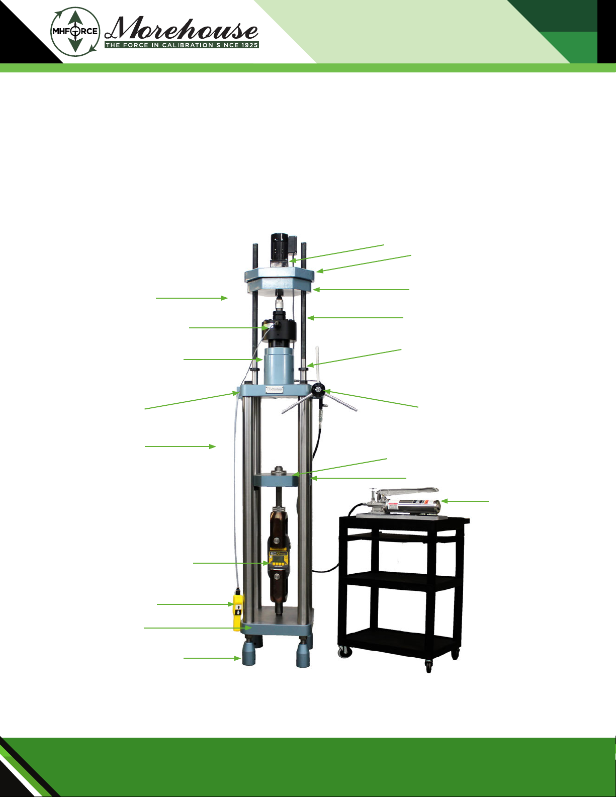
Figure 4: UCM Dimensions
Capacity
required
(kN)
Model
designation1
Max
capacity
A L Max2L Min2M Max2M Min2Size
50 UCM-11xy-01 50 TBD TBD TBD TBD TBD Standard
50 UCM-11xy-02 50 1 220 340 50 320 30 Compact
100 UCM-30xy-01 133 2 440 570 80 1 110 620 Standard
100 UCM-30xy-02 133 1 900 570 80 570 80 Compact
250 UCM-60xy-01 266 2 670 580 80 1 160 670 Standard
250 UCM-60xy-02 266 2 060 600 80 570 50 Compact
500 UCM-112xy-01 500 2 860 610 80 1 180 650 Standard
500 UCM-112xy-02 500 2 340 620 80 670 130 Compact
1 000 UCM-225xy-01 1 000 3 040 720 170 920 370 Standard
1 500 UCM-338xy-01 1 500 3 360 750 200 1 050 500 Standard
3 000 UCM-675xy-01 3 000 4 010 880 260 1 280 660 Standard
5 000 UCM-1125xy-01 5 000 4 870 1 020 280 1 370 630 Standard
Table 2: UCM kN Dimensions (mm)
Technical Specicaons

Universal Calibrang Machine
(UCM) Manual
(PM-5201)
Morehouse Instrument Company, Inc.
1742 Sixth Ave., York, PA 17403-2675 USA
Phone: (717) 843-0081
www.mhforce.com
Page 9
Rev. 11/2021
The Universal Calibrang Machine consists primarily of two load bearing frames:
Moveable Yoke Assembly
Two tension e bars connect the upper and lower yoke platens. The lower yoke platen is permanently xed in
posion by means of the set screws and tension collar nuts. An aperture in the center of the lower yoke platen
provides for inseron of either an alignment adapter or a tension member (pulling rod). When posioning the
moveable yoke assembly, the e bar locking collars are used to support it on the upper machine platen. The
upper yoke is adjustable to accommodate various calibraon conguraons, and to minimize necessary jack
travel. A motorized posioning mechanism for the upper yoke is standard on all capacity Universal Calibrang
Machines.
Staonary Frame Assembly
The staonary frame assembly consists chiey of two platens connected by e bars. Adjustable feet, together
with a circular level mounted on the lower machine platen, provide the means for leveling the machine. Con-
strucon of the staonary frame assembly assures an extremely rigid support with negligible machine deec-
on, even at capacity load.
2.3 Hydraulic Jack Assembly
The Morehouse hydraulic jack assembly (Figure 5) is specially designed and constructed to be suitable to
perform precise calibraon work. The jack is aached to the top of the upper machine platen to maintain the
vercal axis of the jack precisely in line with that of the calibraon standard and test instrument. Ram travel of
this jack is 1” (25.4 mm) maximum. Hydraulic pressure at capacity load is approximately 4,500 psi (31 026 kPa).
2.4 Loading Power Supply
A hydraulic power system is required to supply, maintain, and adjust the hydraulic uid pressure in a UCM
hydraulic jack in order to provide various calibraon loads. Morehouse provides three oponal hydraulic power
systems for all UCM models based on the needs and condions provided by the user:
1- Hydraulic Hand Pump
2- Universal Hydraulic Pump (UHP)
3- Auxiliary Hydraulic Screw Pump

Universal Calibrang Machine
(UCM) Manual
(PM-5201)
Morehouse Instrument Company, Inc.
1742 Sixth Ave., York, PA 17403-2675 USA
Phone: (717) 843-0081
www.mhforce.com
Page 10
Rev. 11/2021
Figure 5: Hydraulic Hand Pump Assembly Connected to Jack Assembly
Ram Vernier Piston
High/Low Selector
Drip Pan
Relief Valve
Quick-Disconnect Coupling
High-Pressure Hose
Air Bleed Plug
Hydraulic Hand Pump
The basic and low-cost system to provide hydraulic pressure for a UCM is a Morehouse hand pump (Figure 5).
When this system is purchased with a UCM, the hydraulic jack is acvated by a hand pump assembly that ad-
vances the ram quickly, then more slowly unl the desired load is achieved. The high/low operaon is switched
manually, and can be switched at any desired load. The pump is connected to the hydraulic jack by means of a
hydraulic hose assembly with a quick-disconnect coupling.
Cauon: Before use, check the hose and ngs for any potenal leaks.

Universal Calibrang Machine
(UCM) Manual
(PM-5201)
Morehouse Instrument Company, Inc.
1742 Sixth Ave., York, PA 17403-2675 USA
Phone: (717) 843-0081
www.mhforce.com
Page 11
Rev. 11/2021
Universal Hydraulic Pump (UHP)
The Morehouse Universal Hydraulic Pump (UHP) is comprised of an electric motor driven pump that eliminates
the eort required to operate the hand pump. It is available for use with calibrang machines of capacies
60,000 lbf (250 kN) and higher. The hydraulic uid ow for UHP units is adjusted by Morehouse based on the
capacity and size of the machine. The operator uses the momentary switch in front of the unit to acvate the
electric motor and run the hydraulic pump. Universal Hydraulic Pump (UHP) is connected to the hydraulic jack
through a hydraulic hose assembly.
Cauon: Before use, check the hose and ngs for any potenal leaks.
Figure 6: Morehouse Universal Hydraulic Pump

Universal Calibrang Machine
(UCM) Manual
(PM-5201)
Morehouse Instrument Company, Inc.
1742 Sixth Ave., York, PA 17403-2675 USA
Phone: (717) 843-0081
www.mhforce.com
Page 12
Rev. 11/2021
Auxiliary Hydraulic Screw Pump
The Morehouse Auxiliary Hydraulic Screw Pump is a manual hydraulic power system that is specically de-
signed to adjust and maintain the calibraon force in a UCM at very ne level. This oponal add-on gives the
operator exceponal control over the calibraon force and enables accurate calibraon at any desired force.
The Auxiliary Hydraulic Screw Pump can be installed on the UCM frame directly, or mounted on the body of
the Universal Hydraulic Pump unit for easier handling. Figure 7 shows the Auxiliary Hydraulic Screw Pump
mounted on both the UCM frame and UHP unit.
Figure 7: Auxiliary Hydraulic Screw Pump Mounted on: a) UCM Frame;
b) Universal Hydraulic Pump
(a)
(b)

Universal Calibrang Machine
(UCM) Manual
(PM-5201)
Morehouse Instrument Company, Inc.
1742 Sixth Ave., York, PA 17403-2675 USA
Phone: (717) 843-0081
www.mhforce.com
Page 13
Rev. 11/2021
3.1 Unpacking
Go to hps://bit.ly/3pzWeAW and watch a video on how to unpack the machine.
Each Universal Calibrang Machine is assembled and tested at the factory prior to shipment. The calibrang
machine is packed completely assembled, as a unit, in a single crate. The lower yoke platen is bolted to the
lower machine platen to form a rigid assembly for shipment, and the hand pump assembly is disconnected
from the jack and aached separately to the shipping crate.
The uncrang procedure is straighorward. With the crate in a horizontal posion, remove the packing materi-
al from the crate, being careful to check for small parts and accessories that may be packed with the calibrang
machine, including the hydraulic hose.
Cauon: Before liing, ensure the unit does not exceed the capacity of the liing equipment.
3.2 Installaon
Installaon consists of seng the machine in place on a smooth, at surface, and leveling the machine by
means of the adjustable feet, using the circular level as an indicator. The 10,000 lbf (50 kN) capacity machine is
normally placed on a bench or sturdy table. Larger machines are usually installed adjacent to a bench or other
suitable work surface to which the hand pump can be fastened. Note: Selecon of a locaon where an even
temperature prevails will greatly facilitate calibraon.
Aer the machine has been installed in posion, remove the bolt that holds the lower yoke to the lower
machine platen. Next, operate the hand pump to extend the ram of the hydraulic jack approximately 1/16 to
1/8 inch. Loosen the e bar locking collars and raise the lower yoke platen unl the lower surface of the upper
yoke platen is within 1/8 inch of the shoulders of the tension e bars.
Note: Be careful not to run the upper yoke platen up against the shoulders of the tension e bars as this may
damage the calibrang machine.
Next, slide the locking collars down the tension e bars to the upper machine platen, and rmly ghten the
locking collar set screws. Now raise the upper yoke platen so there is sucient space to insert the force stan-
dard between the hydraulic jack and the upper machine platen.
Note: Be careful not to run the upper yoke platen against the stops near the end of the threads of the tension
e bars as this may damage the calibrang machine.
3. Preparaon for Use

Universal Calibrang Machine
(UCM) Manual
(PM-5201)
Morehouse Instrument Company, Inc.
1742 Sixth Ave., York, PA 17403-2675 USA
Phone: (717) 843-0081
www.mhforce.com
Page 14
Rev. 11/2021
3.3 Installaon of a Reference Standard
A reference standard, which is normally a load cell, must be installed in a Morehouse UCM before the using
the machine. The reference standard is used to measure the applied force and calibrate the unit under test.
Reference standards need to be calibrated periodically by higher accuracy standards such as those provided by
the Morehouse Force Calibraon Laboratory. A Morehouse reference standard kit can be ulized to install the
reference standard into a UCM. This kit consists of Morehouse reference standards, which are typically load
cells and the adapters necessary to ensure proper force applicaon. The kit shown in Figure 8 is typically used
for force standards with capacies of 100,000 lbf (500 kN) and lower. This kit contains:
1- Load Pad
2- Load Ball Compression Adapter
3- Reference Load Cell
4- Alignment Plug
5- Jack Compression Block
Figure 8: Reference Standard Installation Kit for Load Cells
with Capacities of 100,000 lbf (500 kN) or Lower

Universal Calibrang Machine
(UCM) Manual
(PM-5201)
Morehouse Instrument Company, Inc.
1742 Sixth Ave., York, PA 17403-2675 USA
Phone: (717) 843-0081
www.mhforce.com
Page 15
Rev. 11/2021
If the capacity of the reference standard load cell is higher than 100,000 lbf (500 kN), then the kit shown in
Figure 9 can be used to install the standard in a UCM. The kit contains the following:
1- Top Block Compression Adapter
2- Reference Load Cell
3- Load Cell Alignment Plug
4- Jack Compression Block
Figure 9: Reference Standard Installation Kit for Load Cells
with Capacities Higher than 100,000 lbf (500 kN)

Universal Calibrang Machine
(UCM) Manual
(PM-5201)
Morehouse Instrument Company, Inc.
1742 Sixth Ave., York, PA 17403-2675 USA
Phone: (717) 843-0081
www.mhforce.com
Page 16
Rev. 11/2021
3.4 Preparing the Hand Pump for Use
Before connecng the hand pump assembly to the jack, check the supply of uid in the pump reservoir by
removing the ll plug (item 30 in Figure 15). The ll plug must be le open about two turns during operaon
to serve as a reservoir vent. If hydraulic uid must be added, then be sure to use petroleum based an-wear
hydraulic uid with an ISO Viscosity Grade of 22 or 32. The following hydraulic uids are recommended, but
any equal hydraulic uid may also be used:
Arco .................................................... Dutro AW 32
Conoco ................................................. Super Hydraulic 32
Drydene Oil Co ........................................... Paradene 22 AW
Exxon................................................... .Nuto H 32
Gulf .................................................... Harmony 32 AW
Mobil ................................................... DTE 24
Texaco .................................................. Rando HD 32
Union................................................... Unax AW 150
In choosing a hydraulic uid be certain it is equal to one of the above listed recommendaons. Many formu-
laons may lack certain addives or are formulated for special reasons, such as lower cost, high detergency,
leakage control, etc. Some of these uids can be used successfully, however, others may prompt malfuncons
and high rates of wear.
3.5 Preparing the Jack Assembly for Use
All hydraulic jack assemblies are furnished with a self-sealing hose coupling and are fully bled and checked at
the factory prior to shipment. However, if the hand pump and hydraulic jack seem rather “spongy” during use,
then there may be air in the system. If this occurs, then the system will need to be bled of the entrapped air.
The procedure for bleeding the entrapped air is outlined in Secon 6.2.

Universal Calibrang Machine
(UCM) Manual
(PM-5201)
Morehouse Instrument Company, Inc.
1742 Sixth Ave., York, PA 17403-2675 USA
Phone: (717) 843-0081
www.mhforce.com
Page 17
Rev. 11/2021
4.1 Operang Condions
Calibraon is best performed under the standard condions recommended by the manufacturer of the test
instrument. Precision test instruments usually are calibrated in a locaon where the temperature is maintained
within certain prescribed limits, and where the calibraon standard and test instrument are not subjected to
sudden changes in temperature. It is recommended, therefore, that the Morehouse Universal Calibrang Ma-
chine be installed and used where such condions prevail.
The calibrang machine is designed for calibraon of both tension type and compression type test instru-
ments. Figure 10 illustrates the suggested calibraon setups for tension and compression.
Figure 10: Calibrating Instruments in a) Compression; b) Tension
4. Operaon
(a) (b)

Universal Calibrang Machine
(UCM) Manual
(PM-5201)
Morehouse Instrument Company, Inc.
1742 Sixth Ave., York, PA 17403-2675 USA
Phone: (717) 843-0081
www.mhforce.com
Page 18
Rev. 11/2021
4.2 Compression Setup
The Morehouse Universal Calibrang Machine is setup for compression calibraon in two steps:
1. Posioning the reference standard, such as a Morehouse Proving Ring or Morehouse Load Cell
2. Posioning the unit under test
Prior to use, the machine should be set on a solid surface and leveled by adjusng the feet. Selecng a locaon
where an even temperature prevails will facilitate the calibraon.
Operate the hand pump to extend the ram of the hydraulic jack approximately 1/16 to 1/8 inch before making
the calibraon setup. Verify that the upper yoke platen is posioned so that there is sucient space between
the hydraulic jack and the upper machine platen to insert the reference standard with several inches of thread
on the yoke e bars remaining above the upper yoke platen. Be sure to include an allowance for the height of
any accessories or adapters to be used with the reference standard.
If sucient space cannot be obtained, then adjust the upper yoke platen as follows:
Note: When adjusng the upper yoke platen be careful not to run it against the shoulders or the stops on the
tension e bars as this may damage the calibrang machine.
a) By means of the motor control, lower the upper yoke platen unl it rests on the hydraulic jack.
b) Connue to operate the yoke adjusng mechanism unl the lower surface of the upper yoke platen is within
1/8 inch of the shoulders of the tension e bars.
c) Loosen the screws on the e bar locking collars, lower the locking collars onto the upper machine platen,
and ghten the screws rmly.
d) By means of the motor control, raise the upper yoke platen suciently to accommodate the reference stan-
dard plus any accessories or adapters that will be used with it.
Once the yoke has been posioned to accommodate the reference standard, place the reference standard
on the ram of the hydraulic jack. It is advisable to use an adapter to properly align and secure the reference
standard (Figure 11, A) on the jack ram (Figure 11, C). A complete list of accessories and adapters for use with
Morehouse Universal Calibrang Machines is available at www.mhforce.com.

Universal Calibrang Machine
(UCM) Manual
(PM-5201)
Morehouse Instrument Company, Inc.
1742 Sixth Ave., York, PA 17403-2675 USA
Phone: (717) 843-0081
www.mhforce.com
Page 19
Rev. 11/2021
Next, as shown in Figure 12, place a hardened alloy steel loading ball (B) of the proper size and load rang in
the ball seat of the reference standard (C) and lower the upper yoke platen (A) unl the ball seat of the platen
rests on the ball.
Figure 11:
A) Lower Boss of Reference Standard
B) Ring Alignment Bushing
C) Jack Ram
Figure 12:
A) Upper Yoke Platen
B) Hardened Steel Alloy Load Ball
C) Jack Ram Upper Boss of Reference Standard
If the reference standard is not provided with a ball seat, a suitable adapter should be used. Do not confuse a
lathe center, oen found on instruments, with properly machined ball seats.
Note: Do not interchange hardened alloy steel loading balls, retainer clips with hardened alloy steel loading
balls between dierent reference standards. They should be matched with a reference standard and used only
with that standard.
In cases where the reference standard does not have a ball seat, proper axial alignment is dicult to achieve
when the proper accessories and adapters are not used. To more easily maintain proper axial alignment, it is
recommended that a reference standard with a ball seat be used whenever possible.

Universal Calibrang Machine
(UCM) Manual
(PM-5201)
Morehouse Instrument Company, Inc.
1742 Sixth Ave., York, PA 17403-2675 USA
Phone: (717) 843-0081
www.mhforce.com
Page 20
Rev. 11/2021
With the reference standard in place and the upper yoke platen lowered to rest on the steel loading ball (or
other adapter), release the lock collars, and measure the distance between the upper machine platen and the
lower yoke platen. This distance should be approximately the height of the test instrument plus any acces-
sories or adapters to be used. If it is not, then raise or lower the lower yoke platen unl the correct space is
achieved. To raise or lower the lower yoke platen, proceed as follows:
a) Loosen the screws on the e bar collars and raise them above the upper machine platen.
Cauon: Never loosen the screws on the e bar locking collars unless the reference standard or the hydraulic
jack supports the enre weight of the moveable yoke.
b) Using the motorized adjusng switch, push the switch up/down to raise/lower, the lower yoke platen.
c) When the desired adjustment has been achieved, posion the e bar locking collars to allow clearance be-
tween them and the upper machine platen. Then rmly ghten the screws to hold them in place.
Next, mount the test instrument on the lower yoke platen as shown in Figure 10a. If the test instrument has a
tapped central hole in its base, it should be mounted by an alignment plug to assure proper posioning of the
test instrument on the loading axis of the machine. The alignment plug should be threaded far enough into
load cell to align, not load on the alignment plug. A test instrument with a circle of tapped mounng holes in
its base should be rst mounted to an adapter plate that is counter-bored so that all the bolt heads are com-
pletely recessed.
Check for clearance between the adapters used to load against the top of the test instrument and the under-
side of the upper machine platen. This clearance should be approximately 1/8 inch. If the clearance is greater
than 1/8 inch, then raise the lower yoke platen as needed. Always check to be sure there is clearance between
the test instrument, its adapters, and the upper machine platen.
Cauon: Never load the test instrument directly against the underside of the upper machine platen. Loading
directly against the upper machine platen may result in high unit stress and damage the platen. Proper acces-
sories, such as alignment bearing blocks or so steel pads used with hardened steel bearing plates should be
used to decrease the unit stress to safe levels.
This manual suits for next models
24
Table of contents
Other Morehouse Industrial Equipment manuals
Popular Industrial Equipment manuals by other brands

ABB
ABB HT604478 Operation manual

Graco
Graco ProMix II Service and Parts

HBK
HBK RTN/M2 Mounting instructions

Syn-Tech Systems
Syn-Tech Systems FuelMaster FMU-2500 Classic installation manual

Montanari
Montanari MGX90 ELEVO Use and maintenance

Trident
Trident AirPrime SC 1906 Wildland Unit Installation and operation manual