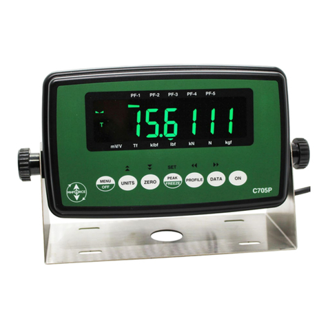
Morehouse 4215 Plus User manual

Model 4215 Plus
Smart Indicators
Morehouse Instrument Company, Inc.
1742 Sixth Ave, York PA 17403 USA
Tel: (717) 843-0081, Fax: (717) 846-4193
www.mhforce.com

MOREHOUSE INSTRUMENT COMPANY INC. MODEL 4215 PLUS V5.0.6
Model 4215 Plus Pg. 1 PUB.6396-02
Morehouse Instrument Company, Inc. Tel: (717) 843–0081
WARRANTY AND LIMITATION OF LIABILITY
All equipment, software, and documentation is sold subject to the mutual agreement that
it is warranted by the company to be free from defects of material and workmanship but
the company shall not be liable for special, indirect or consequential damages of any
kind under this contract or otherwise. The company’s liability shall be limited exclusively
to replacing or repairing without charge, at its factory or elsewhere at its discretion, any
material or workmanship defects which become apparent within one year from the date
on which the equipment was shipped, and the company shall have no liability of any kind
arising from the installation and/or use of the apparatus by anyone. The buyer by the
acceptance of the equipment will assume all liability for any damages which may result
from its use or misuse by the buyer, his or its employees, or by others.
The warranties of the company do not cover, and the company makes no warranty with
respect to any defect, failure, deficiency, or error which is:
A) Not reported to the company within the applicable warranty period; or
B) Due to misapplication, modification, disassembly, abuse, improper installation by
others, abnormal conditions of temperature, dirt, or corrosive matter; or
C) Due to operation, either intentional or otherwise, above rated capacities or in an
otherwise improper manner.
The company believes that the information in this manual is accurate. The document has
been carefully reviewed for technical accuracy. In the event, that technical or
typographic errors exist, the company reserves the right to make changes to subsequent
editions of this document without prior notice to holders of this edition. The reader should
consult the company if errors are suspected. In no event shall the company be liable for
any damages arising out of or related to this document or the information contained in it.
There are no other warranties, expressed or implied including the implied warranties of
merchantability and fitness for a particular purpose.
COPYRIGHT
Under the copyright laws, this publication may not be reproduced or transmitted in any
form, electronic or mechanical, including photocopying, recording, storing in an
information retrieval system, or translating, in whole or in part, without the prior consent
of Morehouse Instrument Company, Inc.
January 27, 2022 Morehouse Instrument Company. All rights reserved.

MOREHOUSE INSTRUMENT COMPANY INC. MODEL 4215 PLUS V5.0.6
Model 4215 Plus Pg. 2 PUB.6396-02
Morehouse Instrument Company, Inc. Tel: (717) 843–0081
CONTENTS
WARRANTY AND LIMITATION OF LIABILITY.................................................................................1
COPYRIGHT ................................................................................................................................................1
CONTENTS ...................................................................................................................................................2
INTRODUCTION .........................................................................................................................................5
QUICK START .............................................................................................................................................7
RUN MODE...................................................................................................................................................8
ITEM BUTTON...................................................................................................................................................9
UNIT BUTTON ..................................................................................................................................................9
TARE BUTTON..................................................................................................................................................9
RESET BUTTON ................................................................................................................................................9
VIEW BUTTON ................................................................................................................................................10
PRINT /HOLD BUTTON ...................................................................................................................................10
SETUP MODE SUMMARY.......................................................................................................................11
SETUP MODE.............................................................................................................................................12
ENTERING NUMERICAL AND ALPHANUMERICAL DATA..................................................................................13
>USER DATA ENTRY......................................................................................................................................13
>>Base Area Entry...................................................................................................................................13
>>Base Length .........................................................................................................................................13
>ANALOG OUTPUT.........................................................................................................................................13
>SENSOR OPTIONS .........................................................................................................................................14
>CALIBRATION...............................................................................................................................................15
>>Cal Check ............................................................................................................................................15
>>Two Point mV/V...................................................................................................................................15
>>Five Point mV/V...................................................................................................................................16
>>Two Pt & Five Pt Data Cal .................................................................................................................16
>>Shunt Cal .............................................................................................................................................16
>>Polynomial Cal ....................................................................................................................................17
>>Counts / Inch........................................................................................................................................17
>LIMITERS .....................................................................................................................................................17
>SYSTEM OPTIONS.........................................................................................................................................18
>>Printer Baud ........................................................................................................................................19
>>Auto Identify ........................................................................................................................................19
>>AutoID Annunciator.............................................................................................................................19
>>Auto Zero Channel...............................................................................................................................19
>>Com Address........................................................................................................................................19
>>Com Baudrate......................................................................................................................................19
>>Com Line Feed.....................................................................................................................................19
>>Retain Tare ..........................................................................................................................................19
>>EOT Char ............................................................................................................................................20
>>Auto Tare .............................................................................................................................................20
>DISPLAY OPTIONS ........................................................................................................................................20
>>Filter Select..........................................................................................................................................20
>>Filter Window ......................................................................................................................................20
>>Decimal Select .....................................................................................................................................21
>>Count By Select....................................................................................................................................21
>>Second Line..........................................................................................................................................21
>>Vel Filter Level ....................................................................................................................................22
>>Max Pos Decimals ...............................................................................................................................22
>>Max Vel Decimals................................................................................................................................22

MOREHOUSE INSTRUMENT COMPANY INC. MODEL 4215 PLUS V5.0.6
Model 4215 Plus Pg. 3 PUB.6396-02
Morehouse Instrument Company, Inc. Tel: (717) 843–0081
REMOTE OPERATION ............................................................................................................................23
DIGITAL INPUTS .............................................................................................................................................23
REMOTE COMMUNICATIONS ..........................................................................................................................24
USB COMMUNICATIONS INFORMATION.........................................................................................24
USB Driver................................................................................................................................................24
Communications Settings..........................................................................................................................24
REMOTE RUN MODE COMMAND SUMMARY .................................................................................26
REMOTE RUN MODE COMMANDS .....................................................................................................26
HELLO COMMAND (H) ...................................................................................................................................26
FRONT PANEL DISPLAY COMMAND (F)..........................................................................................................27
Front Panel View Command (FV) ............................................................................................................27
Front Panel Set Command (FS)................................................................................................................28
Front Panel Alternate Command (FA)......................................................................................................28
Front Panel Pointer Control to Line 1 (F1)..............................................................................................28
Front Panel Pointer Control to Line 2 (F2)..............................................................................................28
Value Command (V)..................................................................................................................................29
PRINT COMMAND (P) .....................................................................................................................................29
RESET TARE,PEAK,VALLEY,AND POSITION COMMAND (R).........................................................................30
HOLD DATA COMMAND (X) OPTIONAL .............................................................................................................31
TEXT DISPLAY COMMAND (T) .......................................................................................................................31
REMOTE SETUP MODE COMMAND SUMMARY .............................................................................32
REMOTE SETUP MODE COMMANDS.................................................................................................33
USER DATA ENTRY COMMAND (U) ...............................................................................................................33
User Data View Command (UV)...............................................................................................................33
User Data Area Command (UA)...............................................................................................................34
User Data Length Command (UL)............................................................................................................34
ANALOG OUTPUT COMMAND (A) ..................................................................................................................34
Analog Output View Command (AV) ........................................................................................................34
Analog Output Set Command (AS)............................................................................................................35
SENSOR COMMAND (S) ..................................................................................................................................35
Sensor View Command (SV) .....................................................................................................................35
Sensor Select Command (SS) ....................................................................................................................36
Sensor Delete Command (SD) ..................................................................................................................36
Sensor View Calibration Points Command (SZ).......................................................................................37
CALIBRATION COMMAND (C) ........................................................................................................................37
Calibration Check Command (CC)...........................................................................................................38
Calibration Begin Command (CB)............................................................................................................38
Calibration Escape Command (CE) .........................................................................................................39
Calibrate by milli-volt per Volt Command for One-Point (CV)................................................................39
Calibrate by milli-volt per Volt Command for Five-Points (CMV5).........................................................40
Calibrate by Polynomial Equation (CP)...................................................................................................40
Calibrate by mV/V Mass and mV/V Volt Commands (CMVM and CMVV) ..............................................41
Calibrate by Masses Command (CM).......................................................................................................43
Calibrate by Masses Point Command (CMP)...........................................................................................43
Calibrate by Shunt Command (CS)...........................................................................................................44
Calibrate Counts-Per-Inch Command (CI)...............................................................................................45
Calibration Counts-per-Inch View Command (CIV) ................................................................................45
Calibration Counts-per-Inch Set Command (CIS)....................................................................................45
LIMITS COMMAND (L)....................................................................................................................................45
Limit View Command (LiV) ......................................................................................................................45
Limit Set Command (LiS)..........................................................................................................................46

MOREHOUSE INSTRUMENT COMPANY INC. MODEL 4215 PLUS V5.0.6
Model 4215 Plus Pg. 4 PUB.6396-02
Morehouse Instrument Company, Inc. Tel: (717) 843–0081
Limit Setup Escape (LE)............................................................................................................................47
Limit Reset Command (LiR)......................................................................................................................47
SYSTEM OPTIONS COMMAND (O)...................................................................................................................47
Option View Command (OV) ....................................................................................................................48
Option Printer Baud Rate Command (OP)...............................................................................................48
Option Auto-Identify Command (OI) ........................................................................................................49
Option Auto-Zeroing Command (OZ).......................................................................................................49
Option Com Address Command (OA).......................................................................................................49
Option Com Baud Rate Command (OB) ...................................................................................................49
Option Line Feed Command (OL) ............................................................................................................50
Option Tare Retain Command (OT)..........................................................................................................50
Option Hold / Freeze (OH) .......................................................................................................................50
DISPLAY OPTIONS COMMAND (D) .................................................................................................................50
Display View Command (DV)...................................................................................................................51
Display Filter Command (DF)..................................................................................................................51
Display Decimal Command (DD) .............................................................................................................51
Display Count By Command (DC)............................................................................................................52
Display Second Line Command (D2)........................................................................................................52
Display Second Line Text (DT) .................................................................................................................52
SYSTEM CALIBRATION MODE .........................................................................................................................53
FORCE AVERAGING (OPTIONAL) ......................................................................................................54
APPENDIX A – MODEL 4215 PLUS SPECIFICATIONS.....................................................................55
APPENDIX B -- CABLES AND CONNECTORS....................................................................................58
SENSOR CONNECTORS....................................................................................................................................58
SERIAL PORT CONNECTOR .............................................................................................................................58
DIGITAL I/O CONNECTOR...............................................................................................................................60
CHART REC.CONNECTOR ..............................................................................................................................61
USB CONNECTOR ..........................................................................................................................................61
PRECISION SHUNT CALIBRATION RESISTORS .................................................................................................62
APPLICATION NOTE: .............................................................................................................................63
MAKE YOUR OWN PLUG-AND-PLAY LOAD CELL SYSTEM AND ELIMINATE COSTLY USER ERRORS .............63
The Problem..............................................................................................................................................63
The TEDS-Tag®Plug-and-Play Solution.................................................................................................63
How to Make the TEDS-Tag®Plug-and-Play Load Cell .........................................................................64
Plug-and-Play Operation..........................................................................................................................66
Under the copyright laws, this publication may not be reproduced or transmitted in any
form, electronic or mechanical, including photocopying, recording, storing in an
information retrieval system, or translating, in whole or in part, without the prior consent
of Morehouse Instrument Company Inc. Copyright January 27, 2022 all rights reserved.

MOREHOUSE INSTRUMENT COMPANY INC. MODEL 4215 PLUS V5.0.6
Model 4215 Plus Pg. 5 PUB.6396-02
Morehouse Instrument Company, Inc. Tel: (717) 843–0081
INTRODUCTION
The Model 4215 Plus is a versatile precision Instrument intended for the digital readout
of Strain Gauge Sensors such as Load Cells. Optical Encoders are also supported.
Here is a quick listing of its features:
•Full bi-polar 6-digit display (±999,999) using two-line, 20-Character, vacuum
fluorescent display for clear, precise indication of measured quantities and limit
status.
•No knobs or dials. No internal jumpers. All adjustment and calibration is done using
user-friendly front panel menus. Keylock option to prevent accidental or
unauthorized changes to the unit’s setup.
•Measure Load linearly or as a Polynomial in pound force (lbf), kilogram force (kgf),
Newtons (N), Pounds per square inch (Psi), MegaPascals (MPa), kilo-pound force
(klb), kilo-Newtons (kN), metric tons (t), milli-volt per Volt (mVV), or gram force (gf).
User defined Base Area for Psi (Pounds per square inch) and MPa (MegaPascals).
Tare at any time.
•Capture the load, peak,valley, gross, polynomial, and optional average.
Displayed in pound force (lbf), kilogram force (kgf), Newtons (N), Pounds per square
inch (Psi), MegaPascals (MPa), kilo-pound force (Klb), kilo-Newtons (kN), metric
tons (t), milli-volt per Volt (mVV), or gram force (gf). Reset at any time.
•Measure position and velocity with Optional Encoder input. Displayed in English
units, metric units, or in percent of a user defined Base Length. Reset at any time.
•Four contact-closure Limit switches. You can set which signal drives the Limit:
(Load, Peak, Valley, Position, Velocity, Gross, Channel Sum, or Polynomial),
normally open / normally closed, set point, and manual reset (latched) or automatic
reset (not latched).
•Print or Hold current readings of Load, Peak, Valley, Position, Velocity, Limit, Gross,
Channel A+B, and Polynomial at the touch of one button.
•Automatic Identification of calibrated Load cells with the Auto-ID option.

MOREHOUSE INSTRUMENT COMPANY INC. MODEL 4215 PLUS V5.0.6
Model 4215 Plus Pg. 6 PUB.6396-02
Morehouse Instrument Company, Inc. Tel: (717) 843–0081
•Calibration for Load cells using manufacturer’s milli-volt per Volt calibration factor
(2- point milli-volt per Volt), 5- point milli-volt per Volt, 2-point data calibration, 5-point
data calibration, shunt calibration, or Polynomial calibration. A back panel switch
allows you to choose between two values used for the Shunt Calibration so there is
no need to open the unit.
•Up to Two Channels of Analog Output of any signal (Load, Peak, Valley, Position,
and Velocity) with user defined scale factor and offset. Large, buffered ±10.00 Volt
output.
•Remote operation using ASCII Commands set via the Serial RS-232/RS-485 port or
the USB port.
•Back panel Digital Inputs for Tare, Peak, and Valley reset, position reset, and print.
Other functions available as custom programmed options.
•Optionally measure the Average Force using a Contact-Closure to begin and end
the averaging period.

MOREHOUSE INSTRUMENT COMPANY INC. MODEL 4215 PLUS V5.0.6
Model 4215 Plus Pg. 7 PUB.6396-02
Morehouse Instrument Company, Inc. Tel: (717) 843–0081
QUICK START
This section will help you get your Model 4215 Plus set up and operating in just a couple
of minutes.
The rear panel is shown below. You will need to make at least two connections here.
First be sure that the power switch is off (the lower part of the rocker should be pressed
in). Connect the AC power line and plug it in.
Next connect a Load Cell to the 9 -Pin (female) connector labeled “Sensor A”. You
should use the cabling supplied with your Model 4215 Plus and Load Cell. If you do not
have a factory-supplied cable, see Appendix B for the recommended Load Cell
connection.
You are now ready to turn on the power. Each time power is applied to the Model 4215
Plus you will see a sequence of 2 messages appear on the front display. For example:
#
Message
Meaning
1
Morehouse X.Y.Z
This is the version number.
2
Serial # 12345
Option # 4653056
This is the serial number.
This is the option number.
Message 1 will be displayed for roughly 4 seconds while message 2 will be displayed for
about 2 seconds. After that the front panel display will start showing the current readings
from the Load Cell.
To change an Item being displayed, press the leftmost button (Item) under the display.
This will cycle through the List of Items available (Load A, Peak A, Valley A, Load B,
Peak B, Valley B, Position, Velocity, Limits, Gross A, Gross B, Channel A+B, Polynomial
A, Polynomial B, and optionally: Avg A and Avg B).
The rightmost button (Unit) will change the Units that are being used. Repeated presses
of this button will cycle through the List of Units available for the currently displayed Item.
For example, with Load A as the Item you would see lbf, kgf, N, Psi, MPa, Klb, kN, t,
mVV, gf, and then back to lbf.
DB9 Sensor A
Power

MOREHOUSE INSTRUMENT COMPANY INC. MODEL 4215 PLUS V5.0.6
Model 4215 Plus Pg. 8 PUB.6396-02
Morehouse Instrument Company, Inc. Tel: (717) 843–0081
RUN MODE
The Model 4215 Plus has three modes of operation: Run Mode, Setup Mode, and
System Calibration Mode. After the startup sequence, the unit will be in Run Mode.
The first Line of the Display shows an Item Label (Load A), a Value (0.0000), and a Unit
Label (lbf).
The Second Line of the Display can show the Status of the 4 Contact-Closure Limit
Switches, show another display, show text, or be blank.
To change an Item being displayed, press the leftmost button (Item) under the display.
This will cycle through the List of Items available (Load A, Peak A, Valley A, Load B,
Peak B, Valley B, Position, Velocity, Limits, Gross A, Gross B, Channel A+B, Polynomial
A, Polynomial B, and optionally: Avg A and Avg B).
The Rightmost Button (Unit) under the display will change the units that are being used.
Repeated presses of this button will cycle through the List of Units available for the
currently displayed Item. For example, with Load A selected as the Item you would see
lbf, kgf, N, Psi, MPa, Klb, kN, t, mVV, gf, and then back to lbf.
The table below summarizes the options.
List of Items
Units for Available Measurement
Load A
(LoadA)
Pound Force, Kilogram Force, Newtons, Psi, MegaPascals, Kilo-
Pound Force, Kilo-Newtons, Metric Tons, mV/V, Gram Force.
Peak A
(PeakA)
Pound Force, Kilogram Force, Newtons, Psi, MegaPascals, Kilo-
Pound Force, Kilo-Newtons, Metric Tons, mV/V, Gram Force.
Valley A
(VallA)
Pound Force, Kilogram Force, Newtons, Psi, MegaPascals, Kilo-
Pound Force, Kilo-Newtons, Metric Tons, mV/V, Gram Force.
Load B
(LoadB)
Pound Force, Kilogram Force, Newtons, Psi, MegaPascals, Kilo-
Pound Force, Kilo-Newtons, Metric Tons, mV/V, Gram Force.
Peak B
(PeakB)
Pound Force, Kilogram Force, Newtons, Psi, MegaPascals, Kilo-
Pound Force, Kilo-Newtons, Metric Tons, mV/V, Gram Force.
Valley B
(VallB)
Pound Force, Kilogram Force, Newtons, Psi, MegaPascals, Kilo-
Pound Force, Kilo-Newtons, Metric Tons, mV/V, Gram Force.
Position (Pos)
Inches, Centimeters, Percent of Base Length.
Velocity (Vel)
Inches per Minute, Centimeters per Minute.
Limits
(Lmts)
Shows state of each switch, 1 for ON, 0 for OFF, dash for
Disabled, asterisk for Source Error.
Gross A
(GrsA)
Pound Force, Kilogram Force, Newtons, Psi, MegaPascals, Kilo-
Pound Force, Kilo-Newtons, Metric Tons, mV/V, Gram Force.
Gross B
(GrsB)
Pound Force, Kilogram Force, Newtons, Psi, MegaPascals, Kilo-
Pound Force, Kilo-Newtons, Metric Tons, mV/V, Gram Force.
Channel A+B
(ChA+B)
Pound Force, Kilogram Force, Newtons, Psi, MegaPascals, Kilo-
Pound Force, Kilo-Newtons, Metric Tons, mV/V, Gram Force.
Polynomial A
(PolyA)
Pound Force, Kilogram Force, Newtons, Psi, MegaPascals, Kilo-
Pound Force, Kilo-Newtons, Metric Tons, mV/V, Gram Force.
Polynomial B
(PolyB)
Pound Force, Kilogram Force, Newtons, Psi, MegaPascals, Kilo-
Pound Force, Kilo-Newtons, Metric Tons, mV/V, Gram Force.

MOREHOUSE INSTRUMENT COMPANY INC. MODEL 4215 PLUS V5.0.6
Model 4215 Plus Pg. 9 PUB.6396-02
Morehouse Instrument Company, Inc. Tel: (717) 843–0081
Avg A
(AvgA)
Pound Force, Kilogram Force, Newtons, Psi, MegaPascals, Kilo-
Pound Force, Kilo-Newtons, Metric Tons, mV/V, Gram Force.
Avg B
(AvgB)
Pound Force, Kilogram Force, Newtons, Psi, MegaPascals, Kilo-
Pound Force, Kilo-Newtons, Metric Tons, mV/V, Gram Force.
All the measurements are acquired via the Model 4215 Plus at all times. The display
allows the user to select a particular Item they choose to view, as well as the Units used
to Display or Print this Data.
Each button has a primary function indicated by the upper set of labels: Item, Unit, Tare,
Reset, View, and Print. These buttons are described in the sections below. Each button
additionally has a secondary function assigned to it (designated by highlighted label) that
is used while navigating within the menus of the Model 4215 Plus:
Pressing the “+” button in some instances will increase values being displayed.
Pressing the “-” button in some instances will decrease values being displayed.
While in a submenu, pressing either the “>” button or the “+”button will scroll forward.
While in a submenu, pressing either the “<” button or the “-” button will scroll backward.
Pressing “Enter” will select the currently displayed option within a submenu.
Pressing “Esc” will return to the previous menu/Run Mode without selecting anything.
Note: All menu lists on the Model 4215 Plus start with the “>” symbol and that the Esc
button will always back out of a menu without making any changes. Each submenu adds
an additional “>” to the title.
Item Button
The Item button cycles through the List of different Items that can be displayed. The List
includes: Load A, Peak A, Valley A, Load B, Peak B, Valley B, Position, Velocity, Limits,
Gross A, Gross B, Channel A+B, Polynomial A, and Polynomial B. optionally Avg A, and
Avg B. Use the Unit button to change the Units for the currently displayed Item on the
Display.
Unit Button
The Unit button cycles through the List of Units that are available for the Item that is
currently being displayed.
Tare Button
The Tare button, as a single channel unit, sets the current Load of Channel A to Zero.
When configured as a 2-channel unit, a submenu will allow you to select Channel A,
Channel B, or All Channels. It does not matter what is being displayed, when you press
this button. The Load is always reset to Zero.
Reset Button
The Reset button brings up a list of things that you might want to set back to Zero:
If this is a 2-channel unit, the following menu will appear:
> Reset Channel A - will reset the Peak and Valley for Channel A.
> Reset Channel B - will reset the Peak and Valley for Channel B.
> Reset Position - will reset the Position to Zero.

MOREHOUSE INSTRUMENT COMPANY INC. MODEL 4215 PLUS V5.0.6
Model 4215 Plus Pg. 10 PUB.6396-02
Morehouse Instrument Company, Inc. Tel: (717) 843–0081
> Reset Limits - will reset any limits that require manual resetting.
> Reset All Channels - will reset the Peak and Valley for Channels A and B.
For a single channel unit, the following menu will appear:
> Reset Peak + Vall - will Reset the Peak and Valley measurements.
> Reset Peak Only - will Reset the Peak measurement.
> Reset Vall Only - will Reset the Valley measurement.
> Reset Position - will Reset the Position to Zero.
> Reset Limits - will Reset any Limits that require Manual Resetting.
View Button
The View button switches between two virtual displays stored in the memory. Each of
the Displays will remember the Units you selected for each Item, as well as which Item is
currently being shown. This may save you from scrolling through the List of Items
especially, if there are two results you use often. For instance, you might set the Display
to show Load in Lbf., press View, and then set the Display for Peak in Psi. Repeated
presses of the View button will now switch back and forth between Load in Lbf. and
Peak in Psi with a single button push. If you choose to have the second line show a
display, then the View button toggles between the Lines. The activated Line to which all
other buttons will apply will have a “>” symbol to the left of it.
Print / Hold Button
The Print / Hold button performs two functions that are user selectable. The two
functions are described below:
Print: As a Print button it will send a set of data to the printer. This will contain the
current readings of Load, Peak, Valley, Position, Velocity, Limit, Gross and Polynomial
status. The units used for printing will be the units last selected on the numerical
display.
The printer must be a serial printer that supports ESC/P protocol. Many Epson printers
with serial ports are known to be compatible. Appendix B gives the Pin Assignments on
the Serial Connector.
Hold: An optional use as a Hold button, pressing it will Freeze the Reading of the unit
until it is pressed again. While in Hold Mode, the unit will still respond to front panel
buttons and Remote Commands (GUI and RS-232). An asterisk character “*” will be
displayed on the 1st character of the line to indicate that the unit is in Hold Mode.

MOREHOUSE INSTRUMENT COMPANY INC. MODEL 4215 PLUS V5.0.6
Model 4215 Plus Pg. 11 PUB.6396-02
Morehouse Instrument Company, Inc. Tel: (717) 843–0081
SETUP MODE SUMMARY
The table below summarizes the Setup Mode Menus. Detailed information about each
individual Item is presented in the following sections.
Setup Options
╠══════
>User Data Entry
║
╠════════
>>Base Area Entry →Channel →Area
║
╚════════
>>Base Length
║
╠══════
>Analog Output
║
║
╚════════
>>Analog Out Setup →Channel →Item →
Units →Full →Zero.
║
╠══════
>Sensor Options
║
╠════════
>>View Cal on Ch A
║
╠════════
>>View Cal on Ch B (2-channel only)
║
╠════════
>>View Sensor Data →Sensor
║
╠════════
>>Select Sensor Data →Channel →Sensor
║
╠════════
>>Delete Sensor Data →Sensor
║
╠════════
>>View Cal Points →Sensor
║
╠════════
>>View Cal mVV Gains →Sensor
║
╚════════
>>View Tag ID →Channel
╠══════
>Calibration
║
╠════════
>>Cal Check →Channel
║
╠════════
>>Two Point mV/V →Channel →Data input
║
╠════════
>>Five Point mV/V →Channel →Data input
║
╠════════
>>Two Pt Data Cal →Channel →Data input
║
╠════════
>>Five Pt Data Cal →Channel →Data input
║
╠════════
>>Shunt →Channel →Data input
║
╠════════
>>Polynomial Cal →Channel →Data input
║
╚════════
>>Counts / Inch
║
╠══════
>Limiters
║
╚════════
Limit Select →State →Enable →
║
Source Item →Units →Set Point→Trip →
║
Latch →Reset Value
║
╠══════
>System Options
║
╠════════
>>Auto Identify
║
╠════════
>>AutoID Annunciator
║
╠════════
>>Auto Zero Channel
║
╠════════
>>Com Address
║
╠════════
>>Com Baudrate
║
╠════════
>>Com Line Feed
║
╠════════
>>Retain Tare
║
╠════════
>>EOT Char
║
╠════════
>>Auto Tare
║
╚══════
>Display Options
╠════════
>>Filter Select
╠════════
>>Filter Window
╠════════
>>Decimals Select →Channel

MOREHOUSE INSTRUMENT COMPANY INC. MODEL 4215 PLUS V5.0.6
Model 4215 Plus Pg. 12 PUB.6396-02
Morehouse Instrument Company, Inc. Tel: (717) 843–0081
╠════════
>>Count By Select →Channel
╠════════
>>Second Line
╠════════
>>Vel Filter Level
╠════════
>>Max Pos Decimals
╚════════
>>Max Vel Decimals
SETUP MODE
Setup Mode is used to change the Setup of the Model 4215 Plus. To enter Setup Mode
press the Item and Unit buttons at the same time. Once in this mode, the front panel
buttons will operate with their secondary functions.
If the Optional Keylock is in the locked position you will see “>Setup is Locked” when you
try to enter Setup Mode. This prevents accidental or unauthorized changes to the Setup
of the unit.
To exit from Setup Mode and return to Run Mode press the escape button (Esc). When
you are entering numerical data, or selecting options from a Submenu the Escape button
will back you out without making any changes.
The Main Menu in Setup Mode contains the following seven (7) entries which will be
described in detail in the following sections. Note:All Main Menu Items begin with the
“>“ symbol and that all submenu Items begin with the “>>“ symbol.
•> User Data Entry ▬allows you to set any common math options such as the Base
Area used to display Load in Psi or the Base Length used to display Position in
percent.
•> Analog Output ▬is used to select the Analog Channel, Source, and Scaling for
the Analog Output Channels.
•> Sensor Select ▬allows the user to manually select/delete which Load Cell
calibration data is used and view data for specific sensors.
•> Calibration ▬provides access to Calibration for Load Cells, Extension Sensors,
or Optical Encoders.
•> Limits ▬allows you to set the Source and options for the 4 Contact-Closure
Switches.
•> System Options ▬contains options for a variety of system level parameters that
can be enabled or disabled or set to user preference.
•> Display Options ▬contains options for a variety of display related parameter
settings that adjust how information is displayed on the front digital display.
The Plus or Right button (“+” or “>”) will scroll forward through this menu. The Minus or
Left button (“-” or “<”) will scroll backward through this menu. The Enter button selects
the currently displayed menu Item. The Esc button will return you to Run Mode or
previous menu option.

MOREHOUSE INSTRUMENT COMPANY INC. MODEL 4215 PLUS V5.0.6
Model 4215 Plus Pg. 13 PUB.6396-02
Morehouse Instrument Company, Inc. Tel: (717) 843–0081
Entering Numerical and Alphanumerical Data
At times you will need to enter numerical or alphanumerical data into the Model 4215
Plus. The method is consistent in all cases. A character is presented on the display with
a blinking underline cursor.
•Left (“<”) moves the cursor left one position. If a numerical entry and you are on the
leftmost digit a new zero will be added. Thus 10.000 will become 010.00 where the
cursor has moved from the tens place to the hundreds place. If an alphanumerical
entry and are on the leftmost character, a new “A” will be added.
•Right (“>”) moves the cursor right one position. If a numerical entry and you are at
the rightmost a new decimal will be added if there is room. Thus 12.34 will become
12.340 where the cursor has moved from the tenths to the hundredths place. If an
alphanumerical entry and are on the rightmost character, a new “A” will be added.
•Plus (“+”) increases the digit above the cursor. Thus 12.34 becomes 13.34. Note
that 9 will “wrap around” to 0 on numerical value entries only. On alphanumerical
entries, “z” will wrap around to 0. Some data entry fields will include additional ASCII
symbols to select from while scrolling with this button.
•Minus (“-”) decreases the digit above the cursor. Thus 12.34 becomes 11.34. Note
that 0 will “wrap around” to 9 on numerical value entries only. On alphanumerical
entries, 0 will wrap around to “z”. Some data entry fields will include additional ASCII
symbols to select from while scrolling with this button.
•Plus and Minus (both “+” and “-” at the same time). This will change the sign of the
number. Thus 12.34 becomes -12.34. Note the cursor position does not matter when
you change the sign.
•Enter accepts the currently displayed value.
•Esc Escapes from data entry and discards any changes that have been made.
>User Data Entry
This menu is used to enter numerical constants used by the math options. These
constants are listed in a submenu that works exactly like the main Setup Mode Menu.
Typical Items in this submenu are:
>>Base Area Entry
After selecting the desired channel, a numerical value in Square Inches that is used
to calculate Load in pounds per square inch (Psi) or MegaPascals (MPa) may be
entered.
>>Base Length
This is the length in Inches that is used to calculate the position in percent.
>Analog Output
This menu is used to set up the Analog Outputs. Instead of a submenu there is a series
of selections. Pressing the Escape button (Esc) at any time will go to the previous
selection until back in the Setup Mode Main Menu.
1. Channel: ▬The Channel Entry allows you to select the Analog Output Channel A or
B (using either the left/right or plus/minus buttons) for the selected Source Data that
will drive the Analog Output. Press Enter to select the displayed Analog Channel.

MOREHOUSE INSTRUMENT COMPANY INC. MODEL 4215 PLUS V5.0.6
Model 4215 Plus Pg. 14 PUB.6396-02
Morehouse Instrument Company, Inc. Tel: (717) 843–0081
2. Item: ▬The Item Entry allows you to scroll through a list (using the left/right or
plus/minus buttons) to select the item source of the Data that will drive the Analog
Output. The standard list will include: Load, Peak, Valley, Position, Velocity, Gross,
Channel A+B, Polynomial, and Average if active. Press Enter to select the displayed
Item.
3. Units: ▬The Units Entry allows you to scroll through the List of available Units for
the Data Source that you have chosen in the previous step.
4. Full Scale:▬The Full Scale Entry specifies the Value of Source Data (in the
selected units) that will cause the Model 4215 Plus to output positive full-scale
Analog Voltage (+10.0 volts).
5. Zero Scale:▬The Zero Scale Entry specifies the value of Source Data (in the
selected units) that will cause the Model 4215 Plus to output zero analog voltage (0.0
volts).
Once you have entered these five (5) selections the Analog Output is setup.
>Sensor Options
The >Sensor Options menu is used to view the current calibration data on each
channel, view all sensor data, manually select Load Cell sensors for each channel or
delete them, view each sensors Cal points and mV/V Gains, and view tag ID data for
each channel if present.
•Use either the Left/Right or Plus/Minus buttons to scroll through the List of data
for each selectable submenu option.
•Pressing the Escape button will return to the previous step, until back to the
Setup Mode Main Menu, without changing any data.
•Pressing the Enter button will select/accept the currently displayed entry. If
selecting a sensor, after this action the sensors calibration data will be available
to scroll through, if this action is not required press enter again to exit.
To add new Load Cells to the list, use the Calibration Entry on the Setup Mode Main
Menu described below.
Note: The Model 4215 Plus can store Calibration Data for 25 different Load Cells /
Sensors. You may need to shut off Auto-ID if it is on - see the System Options
menu for details).

MOREHOUSE INSTRUMENT COMPANY INC. MODEL 4215 PLUS V5.0.6
Model 4215 Plus Pg. 15 PUB.6396-02
Morehouse Instrument Company, Inc. Tel: (717) 843–0081
>Calibration
This menu is used to access all methods of Calibration that are supported by the Model
4215 Plus.
•Selecting “Calibration” from the Setup Mode Main Menu will bring up a submenu.
•The submenu is used exactly like the Main Menu.
•Press left/right or plus/minus to change the Menu Item.
•Press the Escape Button to return to the Setup Mode Main Menu.
•Press the Enter Button to select the displayed menu Item.
If you are re-calibrating a Load Cell, the Model 4215 will recognize it using either the
Auto-ID or a manually entered Serial number.
•Any time you overwrite existing Load Cell Calibration Data, you will first be
warned with the “Overwrite data?” message.
•Pressing the Enter Button will begin the overwriting process.
•Pressing the Escape Button will cancel the calibration, voiding any changes that
have been made.
•Another method to avoid overwriting existing data is to delete the Sensor first and
then Calibrate.
If a Load Cell with a new serial number (or new Auto-ID) is calibrated, the data is added
as a new entry in the Load Cell list.
>>Cal Check
Selecting the >>Cal Check will present you with a channel selection of either A or B.
once a channel is selected is will automatically begin running a Calibration Check on
the Load Cell / Sensor attached to Channel specified.
•The Model 4215 Plus will measure the Shunt Value of the Load Cell and
compare it to the Shunt Value that was recorded when the Load Cell was last
calibrated.
•The last Calibration Date for the Load Cell is displayed followed by the
currently measured Shunt Value and the Shunt Value that was recorded
when the Load Cell was calibrated.
Note:The Model 4215 Plus has a switch on the back panel that allows you to select
either a 30K Shunt or a 60K Shunt. Be sure that this switch is set correctly for the
Load Cell that you are using.
Note: Since this Shunt Check electronically applies approximately half the
Rated Load, it is important that the Load Cell / Sensor is not loaded when this
check is run. If you see the “Cell Overloaded” message, remove any load on
the cell and try the check again.
>>Two Point mV/V
Using >>Two Point mV/V will calibrate a Load Cell using the manufacturer’s Milli-Volt
per Volt Calibration Factor or a series of Milli-Volt per Volt Points with corresponding
Masses (usually listed on the Load Cell Calibration Certificate).
•You will be asked for the Channel, the Cell Serial Number, the current date,
excitation level (5.0 or 10.0 volts), the Calibration Unit, the Load Cell’s
Maximum Rated Load, and the mV/V calibration constant.

MOREHOUSE INSTRUMENT COMPANY INC. MODEL 4215 PLUS V5.0.6
Model 4215 Plus Pg. 16 PUB.6396-02
Morehouse Instrument Company, Inc. Tel: (717) 843–0081
•The Load Cell should not be under load when this Calibration Method is
used since a Shunt Value will be measured and recorded for later use
with the “Cal Check” feature described above. The “No Masses Ready”
message is intended to remind you of this fact.
>>Five Point mV/V
If a >>5-point Milli-Volt per Volt Calibration is selected, you are prompted to enter
each mass and Milli-Volt per Volt value corresponding to that mass.
•One of these points should be a Zero Mass and Zero Milli-Volts per Volt.
•Enter each of these selections or press the Escape Button at any time to
move backward one selectable option without changing the Calibration.
•The Load Cell should not be under load when this Calibration Method is
used since a Shunt Value will be measured and recorded for later use
with the “Cal Check” feature described above. The “No Masses Ready”
message is intended to remind you of this fact.
>>Two Pt & Five Pt Data Cal
The Data Cal options are used to calibrate a Load Cell using known masses.
•You will first be asked for the Channel, the Load Cell Serial Number, the
current date, Excitation Voltage (5.0 or 10.0 volts), the Calibration Unit, and
the cell’s Maximum Rated Load.
•You are then prompted to enter the Value of the First Mass.
•The “Mass 1 Ready?” message will wait, while you physically apply the mass
to the attached Load Cell. Once the mass is applied press the Enter button.
•When the Model 4215 Plus is reading the Load Cell it will display the
“Calibrating Mass 1” on line 1 and “– Reading...” on line 2 messages for
about 10 seconds.
•At this time, it is important that the Masses are not disturbed since all
the readings taken are averaged together to obtain the calibration data.
•The second mass is then prompted to be applied and entered.
•If a 5-point calibration was selected, the process will continue until all masses
have been read. At the end of both calibration methods a reading is also
required with NO MASS on the sensor, indicated by the message “No
Masses Ready?” during this reading a Shunt Check Value is recorded.
>>Shunt Cal
The >>Shunt Cal Item is used to calibrate a Load Cell using the manufacturer’s
Shunt Calibration factor expressed in pounds.
•You will be asked for the Channel, the Load Cell Serial Number, the current
date, Excitation Voltage (5.0 or 10.0 volts), the Calibration Unit, the cell’s
Maximum Rated Load, and the Shunt calibration factor.
•The Model 4215 Plus will then ask, “No Masses Ready” and upon pressing
the Enter button will perform the Shunt Calibration of the Load Cell using its
Internal Precision Shunt Resistor.
•Note: There is a Back Panel Switch that allows you to select either a 30K or
60K Resistor for Shunt measurements (see Appendix B for a circuit diagram).
•Be sure to select the appropriate Value for your Load Cell.

MOREHOUSE INSTRUMENT COMPANY INC. MODEL 4215 PLUS V5.0.6
Model 4215 Plus Pg. 17 PUB.6396-02
Morehouse Instrument Company, Inc. Tel: (717) 843–0081
•During this Calibration the “Calibrate Shunt Command – Reading...” message
will be displayed. Do not disturb the Load Cell while it is being read.
•Like the “Cal by milli-volt per Volt” option, the Load Cell should be free
of load during this calibration.
>>Polynomial Cal
The Polynomial Cal option is used to calibrate a Load Cell using a polynomial
equation. You will first be asked for the Channel, the Load Cell Serial Number, the
current date, Excitation Voltage (5.0 or 10.0 volts), the Calibration Unit, and the cell’s
Maximum Rated Load. Once done the polynomial information can be set. The
equation is broken up into three main parts, Degree, Mantissa, Exponent.
Degree: Will be a number between 0 and 5 and represent the total number
of coefficients present in the polynomial equation. 0 represents 1
coefficient (B0) and 5 represents 6 coefficients (B5). The example
equation below depicts a 3rd degree polynomial.
Force = B0+ B1+ B2r2+ B3R3
Mantissa: is the decimal value that is used while writing a value in scientific
notation. In the two examples of scientific notation depicted in the
below example, the mantissa is 1.2815.
1.2815 E+02 or 1.2815 x10²
Exponent: relates to the exponential value used while writing a number in
scientific notation. In the two examples of scientific notation
depicted in the above example, the exponent is 2.
When a degree of greater than 0 is selected the mantissa and exponent will be
prompted for each degree. For example, if a 1st degree polynomial is desired, the
Model 4215 Plus will prompt you to enter the following values: Mantissa degree 0,
Exponent degree 0, Mantissa degree 1, Exponent degree 1.
Once all values have been entered the unit will ask, “No Masses Ready”, and upon
pressing the Enter button will record a shunt check value.
>>Counts / Inch
The >>Counts / Inch Entry allows you to set the number of counts-per-inch that the
Quadrature Encoder Input will use. Default is 24000 Counts/Inch.
>Limiters
The >Limiters Menu is used to set up the 4 Contact-Closure Switches.
•Instead of a submenu there are a series of selections.
•Pressing the enter button will accept the displayed entry.
•Pressing the escape button will return to the previously selected entry without
changing the currently displayed entry.

MOREHOUSE INSTRUMENT COMPANY INC. MODEL 4215 PLUS V5.0.6
Model 4215 Plus Pg. 18 PUB.6396-02
Morehouse Instrument Company, Inc. Tel: (717) 843–0081
1. Select a Limit:▬The first selection chooses which of the Limiters you want to set
up (Limiter 1 to Limiter 4).
2. Default State:▬An option of making the limiter contacts either Normally Open or
Normally Closed.
3. Enable the Limit?: ▬Choosing Disabled places the Limiter in its “normal” state
and completes the Limiter Setup. Choosing Enabled allows you to continue the
Limiter activation by making the remaining entries available.
4. Limit Source: ▬This selection allows you to scroll through a list (use either the
left/right or plus/minus buttons) to select the Source of the Data that will drive the
Limit. The standard list will include; Load, Peak, Valley, Position, Velocity, Gross,
Channel A+B, Polynomial, and optionally, Average Force. Press the enter button to
select the displayed Item.
5. Limit Units: ▬This entry allows you to scroll through the list of available Units for
the Data Source you have chosen in the previous step.
6. Limit Set Point:▬This is the numerical value of the Source at which the Limit will
be activated (Set Point). It is specified in the units that you chose in the previous
step.
7. Trip if > or <?: ▬Choosing “Source>Set “means that the Limit will be activated
when the Source becomes greater than the Set Point. Choosing “Source<Set”
means that the Limit will be activated when the Source becomes less than the Set
Point.
8. Latching Limit?:▬Selecting “Latching Off” means that the Limit will be de-
activated automatically when the Source passes the Reset Point (see next
selection). Selecting “Latching On” means that once the Limit is activated you must
manually reset it using the Reset button. If you select Latching On, then the Limit
Setup is done.
9. Limit Reset Value:▬This selection determines the numerical value of the Source
at which point the Limit will be deactivated (Reset Point). If you selected
“Source>Set” in step 7 then the Limit is deactivated when the Source is less than the
Reset Point. If you selected “Source<Set” in step 7 then the Limit is deactivated
when the Source is greater than the Reset Point.
Notes:
The Set and Reset conditions for each limit are evaluated independently. If both
conditions are met, then Reset will take priority over Set.
Limit Status may show an asterisk if the Limit is Enabled but there is an error in the
Signal Source. Some examples of a Signal Source error include: a Limit Source is set to
Load but there are no Load Cells currently Calibrated; if the load cell has a rating of 0.0
Lb; or if the milli-volt per Volt Constant is set to Zero. Another example of a Signal
Source error would be if the Limit Source is set to Position and zero has been entered
for the Encoder counts-per-inch Constant. Limits that are in this error condition will be
forced to the off position as if they were disabled.
>System Options
The >>System Options Menu contains some system wide parameters that are seldom
changed. These are listed in a submenu that works exactly like the Setup Mode Main
Menu.

MOREHOUSE INSTRUMENT COMPANY INC. MODEL 4215 PLUS V5.0.6
Model 4215 Plus Pg. 19 PUB.6396-02
Morehouse Instrument Company, Inc. Tel: (717) 843–0081
>>Printer Baud
The front panel Print button and the Remote Print Commands will use this Baud Rate
for communications with your printer. This setting has no effect on units that are not
equipped with the printing option. 57.6K Baud is commonly used on older Serial
Printers and a 230.4K Baud is used on more recent serial printers. 4800, 9600,
19.2k, 57.6k, 230.4k are all the baud Rate options.
>>Auto Identify
The >>Auto Identify (AutoID) allows a user to turn Automatic Load Cell Identification
On or Off. Usually you can leave Auto-ID On, even if you never use Automatic Load
Cell Identification. In order, to use the Auto-ID On function you must either have an
Auto-ID equipped Load Cell or use an In-Line Auto-ID Module attached to your Load
Cell cable.
>>AutoID Annunciator
When the >>AutoID Annunciator is on and Auto Identify is also on there will be a “t”
seen preceding the selected Item on the display while in Run Mode. The “t” will blink
if a non-recognized or non-AutoID cell is attached. If a recognized AutoID cell is
attached, the “t” will change from blinking to solid.
>>Auto Zero Channel
The >>Auto Zero Channel Menu lets the user Enable or Disable Auto Zeroing for
Load measurements on Channel A or Channel B. When Enabled, the >>Auto Zero
Channel function will Tare the Load to Zero any time that it has remained within 10
counts of Zero on the display for 10 seconds.
>>Com Address
The >>COM Address Item allows the user to set the address of the unit used for the
Remote ASCII Command set. Valid values are 001 through 254. If the RS-232
multi-drop option is installed, you must be sure that all the attached units have
different addresses to prevent data collisions.
>>Com Baudrate
The >>Com Baudrate sets the Baud Rate for the Remote ASCII Command set.
Available values are: 300, 600, 1200, 2400, 4800, 9600, 19.2k, 38.4k, 57.6k, and
230.4k.
>>Com Line Feed
The >>COM Line Feed controls whether a Line Feed is added to each carriage
return that is sent out by the Model 4215 Plus when the Remote ASCII Command set
is being used.
>>Retain Tare
The >>Retain Tare controls whether the most recent Tare Value is retained through
the power down of the unit and used again immediately on power up.
Table of contents
Other Morehouse Measuring Instrument manuals
Popular Measuring Instrument manuals by other brands

Agilent Technologies
Agilent Technologies 4291B Operation manual

Rohde & Schwarz
Rohde & Schwarz CMW-KM75 Series user manual

ABB
ABB 8241 operating instructions

Keysight Technologies
Keysight Technologies U1273A quick start guide

Burster
Burster DIGIFORCE 9310 manual

KING
KING 7430 Series installation instructions