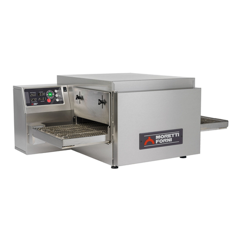
Moretti Forni P110G C/A User manual

Instructions manual
Manuel d’instructions
Gas
oven
Four
a
gaz
Cod.73300890
Ver.: A4
P110G –P150G

UK/1
NOTICE:
This Owner’s Operating and Installation Manual should be given to the user. The operator of the oven should
be familiar with the functions and operation of the oven.
This manual must be kept in a prominent, easily reachable location near the oven.
Gas ovens are designed for use with EITHER natural gas OR liquid LP gas, as specified on the serial plate.
Where permitted by local and national codes, the oven can be converted from natural gas to LP gas operation,
or from LP gas to natural gas operation. This conversion requires the installation of the appropriate Producer
Gas Conversion kit by an Authorized Service Agent.
It is suggested to obtain a service contract with a Producer Authorized service agent.
WARNING
POST, IN A PROMINENT LOCATION, THE EMERGENCY TELEPHONE NUMBER OF YOUR LOCAL
GAS SUPPLIER AND INSTRUCTIONS TO BE FOLLOWED IN THE EVENT YOU SMELL GAS.
Instructions to be followed in the event the user smells gas shall be obtained by consulting the local gas supplier. If
the smell of gas is detected, immediately call the emergency phone number of your local Gas Company. They will
have personnel and provisions available to correct the problem.
FOR YOUR SAFETY
Do not store or use gasoline or other flammable vapors or liquids in the vicinity of this or
any other appliance.
WARNING
Improper installation, adjustment, alteration, service or maintenance can cause property
damage, injury or death. Read the installation, operating and maintenance instructions
thoroughly before installing or servicing this equipment.
IMPORTANT
The label with the electric circuit arrangement is on the right lateral side (on the models
P110G) / rear (on the models P110G) / rear (on the models P110G) of the oven.
IMPORTANT
It is the customer’s responsibility to report any concealed or non-concealed damage to the
freight company. Retain all shipping materials until it is certain that the equipment has not
suffered concealed shipping damage.
NOTICE: CONTACT YOUR PRODUCER TO PERFORM MAINTENANCE AND REPAIRS.
NOTICE: Using any parts other than genuine Producer manufactured parts relieves the manufacturer of all warranty
and liability.
NOTICE: Producer reserves the right to change specifications at any time.
NOTICE: The equipment warranty is not valid unless the oven is installed, started and demonstrated under the
supervision of a factory certified installer.
Retain This Manual For Future Reference
Moretti Forni S.P.A. Via A. Meucci, 4 –61037 Mondolfo (PU) ITALIA –Tel. +39-0721-9.61.61 –Fax +39-0721-9.61.62.99
www.morettiforni.com

UK/2
INDEX
01 TECHNICAL DATA 3
02 INSTALLATION 4
03 OPERATION 6
04 ORDINARY MAINTENANCE 7
05 SPECIAL MAINTENANCE 7
06 NOISE LEVELS 9
07 LIST OF SPARE PARTS 9
Note:
This catalogue is printed in two languages: English and French.
WARRANTY
Standards and rules
Warranty only covers the replacement free to factory of pieces eventually broken or damaged because of faulty materials or manufacture.
Warranty does not cover any damages caused by third party transport or due to incorrect installation or maintenance, to carelessness or
negligence in usage, or to tampering by a third party. Moreover, warranty does not cover: glass components, covers, bulbs and whatever
depends on normal wear and deterioration of both the system and its accessories; nor does it cover labour costs involved in replacing pieces
covered by warranty.
Warranty ends in case of non-compliance with payments and for any elements that may be repaired, modified or disassembled, even in part, without
prior written consent. For technical service during the warranty period, please send a written request to the local concessionary agent or directly to the
Sales Department.
WARNING
This word indicates a danger, and will be employed every time the safety of the operator might be involved.
NOTE
This word indicates the need for caution, and will be employed to call attention to operations of primary importance for correct and long-term
operation of the appliance.
DEAR CUSTOMER
Before using the appliance, please read this user manual.
For the safety of the operator, the appliance safety devices should always be maintained in a proper state of efficiency.
This user manual intends to illustrate use and maintenance of the appliance. For this reason, the operator is advised to follow the instructions given
below.
The manufacturer reserves the right to make improvements to the product and manual, without necessarily updating existing products and manuals.
WARNING!
1. The following instructions are provided for your safety.
2. Please read them carefully before installing and using the appliance.
3. Keep this user manual in a safe place for future consultation by the operators.
4. All installation operations, changes made in order to use different types of gas, adjustments and special maintenance operations, must
be carried out in compliance with the Manufacturer’s instructions by a qualified technician. Sealed parts must not be adjusted or
tampered with except for the transformations that are foreseen.
5. The nozzles and the technical rating plate for allowed transformation are supplied in a bag along with the oven and must be kept with
all the oven documentation.
6. This appliance must only be employed for the purposes for which it was designed: to cook pizza or similar food products. It is
prohibited to bake products containg alcohol. Any other use can be classed as improper.
7. The appliance is intended only for collective use and must be used only by a qualified professional user trained to operate it. The
appliance mustn’t be used by children.
8. When carrying out repairs, always contact one of the Manufacturer’s authorised service centres and request that original spare parts
be used.
9. Failure to comply with the above may compromise the safety of the appliance.
10. In the event of breakdown or malfunction always disconnect the appliance, and do not attempt to make adjustments or repairs yourself.
11. Should the appliance be sold or transferred to another owner, or should the current owner change his premises and wish to install the
appliance elsewhere, always ensure that this manual remains with the appliance, so that it can be consulted by the new owner and/or
the person carrying out installation.

UK/3
1 TECHNICAL DATA
1.1 DESCRIPTION OF THE OVEN
The oven comprises several units positioned one on top of the other, which
basically form two distinct and complementary elements:
- upper baking chamber/s
- lower stand or proofer
-optional spacer ring 11 13/16” (300mm) thick between the chamber/s
and stand/compartment
The baking section comprises an insulating element (hood) and 1 or 2 or 3
baking chambers.
Each baking chamber is totally independent and has electronic temperature
regulation, a safety thermostat, electronic safety burner control and a
bottom-hinged door.
The lateral and upper internal structure is in aluminised metal plate, while
the cooking surface is refractory for direct contact cooking or pan cooking.
The lower unit can be used as support for the cooking element and it can
be either open or closed.
The open unit (support element) comprises a steel structure fitted with tray
holder guides.
The closed unit (proofer) comprises a steel structure which is panelled, has
tray holder guides and is fitted with a thermostat for heating.
1.2 REGULATIONS APPLIED
This oven complies with the following:
UL STD 197
NSF STD 4
ANSI STD Z83.11
CAN/CSA C22.2 STD No.109
CSA STD 1.8
1.3 WORKPLACES
The ovens are programmed by the operator using the control switchboards
on the front of the oven, and they must be attended to while in operation.
The doors giving access to the ovens are located at the front.
1.4 MODELS
There are nine models available:
- P110G C/A
- P110G C/B
- P150G C/A
- P110G C/A2 (double chamber)
- P110G C/B2 (double chamber)
- P150G C/A2 (double chamber)
- P110G C/A3 (triple chamber)
- P110G C/B3 (triple chamber)
- P150G C/A3 (triple chamber)
The following compositions are not possible
(P110G C/A2-B2, P150G C/A2)+P110/150 L/80+ANELLO P110/P150
(P110G C/A2-B2, P150G C/A2)+P110/150 CV/80+ANELLO P110/P150
(P110G C/A2-B2-A3-B3, P150G C/A2-A3) + P110/150 CV/95
(P110G C/A3-B3, P150G C/A3) + P110/150 CV/80
(P110G C/A3-B3, P150G C/A3) + P110/150 L/80
Any support that is not supplied by the manufacturer must be of a type
suitable to guarantee the appliance a proper level of stability
1.5 TECHNICAL DATA (see TABLE 1)
1.6 DIMENSIONS AND WEIGHTS (see Fig.1)
1.7 IDENTIFICATION
When communicating with the manufacturer or service centre, always give
the oven SERIAL NUMBER, which can be found on the plate fixed as
shown in fig.2.
1.8 LABELLING
The oven is supplied with warning labels at the points shown in fig.2 - 3.
- C - electric diagram plate
- D - control board working plate
- E - plate “English warning pre-installation”
- F - plate “French warning pre-installation”
- G - wheels presence plate
- H - plate “Wall distance”
- I - plate “LP-GAS 10,5 inWC –26,2 mbar C-US”
- L - plate “NATURAL GAS 4 inWC –10 mbar C-US”
-M - Sign "PROOFER SANITATION"
-N - label “GAS U.S. AND CANADA AND SANITATION”
- O - label “ELETTRICO U.S. AND CANADA AND SANITATION”
-P - label “LAMP”
1.9 ACCESSORIES
The oven is equipped with the following accessories:
-set of nozzles for replacing those provided.
-alternative technical rating plate

UK/4
2 INSTALLATION
WARNING –For gas ovens, after any conversions, readjustments, or service work on the oven:
-Perform a gas leak test.
-Test for correct air supply.
-Test for proper combustion and gas supply.
-Check that the ventilation system is in operation.
WARNING
For electric ovens, after any conversions, readjustments, or service work on the oven, check that the ventilation
system (if so equipped) is in operation.
WARNING
Keep the appliance area free and clear of combustibles.
WARNING
The oven must be installed on an even (level) non-flammable flooring and any adjacent walls must be non-
flammable. Recommended minimum clearances are specified in the Description section of this manual.
WARNING
Do not obstruct the flow of combustion and ventilation air to and from your oven. There must be no obstructions
around or underneath the oven. Constructional changes to the area where the oven is installed shall not affect the
air supply to the oven.
CAUTION
For additional installation information, contact your local Authorized Service Agent.
NOTE
There must be adequate clearance between the oven and combustible construction. Clearance must also be
provided for servicing and for proper operation.
NOTE
The label with the electric circuit arrangement is on the right lateral side (on the models P110G) / rear (on the
models P110G) of the oven.
NOTE
All aspects of the oven installation, including placement, utility connections, and ventilation
requirements, must conform with any applicable local, national, or international codes. These codes
supercede the requirements and guidelines provided in this manual.
NOTE
In the USA, the oven installation must conform with local codes. In the absence of local codes, gas
oven installations must conform with the National Fuel Gas Code, ANSI Z223.1. Gas and electric
ovens, when installed, must be electrically grounded in accordance with local codes, or in the
absence of local codes, with the National Electrical Code (NEC), or ANSI/NFPA70.
NOTE
In Canada , the oven installation must conform with local codes. In the absence of local codes, gas
oven installations must conform with the Natural Gas Installation Code, CSA-B149.1, or the Propane
Gas Installation Code, CSA-B149.2, as applicable. Gas and electric ovens, when installed, must be
electrically grounded in accordance with local codes, or in the absence of local codes, with the
Canadian Electrical Code CSA C22.2.

UK/5
2.1 TRANSPORT
The oven is generally delivered fastened to wooden pallets (fig. 4).
Each part is protected by a plastic film or by cardboard boxes.
2.2 UNLOADING
NOTE! On receiving the oven, it is advisable to check its conditions
and quality.
Remove the metal seals (fig. 9 item E) if already fitted to the relief
channels (fig. 9 item C).
Raise the equipment using only and exclusively the points indicated at the
pict. 5.
2.3 ENVIRONMENTAL SPECIFICATIONS
To ensure that the oven operates properly, it is advisable to comply with
the following limits:
Working temperature: +41F (+5°C) ÷ +104F (+40°C)
Relative humidity: 15% ÷ 95%
2.4 POSITIONING, ASSEMBLING AND MAINTENANCE
AREAS
WARNING! When positioning, assembling and installing the oven,
the following specifications have to be complied with:
- Laws and standards in force regarding the installation of gas
appliances in large kitchens.
- Laws and standards in force regarding technical regulations for gas
appliances.
- Laws and standards in force regarding technical regulations for
LPG.
- Directives and indications issued by the gas supply network.
- Directives and indications issued by the electricity supply network.
- Local building and fire-prevention laws.
- Accident prevention regulations.
-Regulations in force of the electromechanical rules.
The appliances must be installed in conformity with current
national regulations.
Remove the protective film from the outside of the oven, pulling it gently
to remove all the adhesive.
Should any adhesive remain on the oven, remove using kerosene or
benzene.
The single elements must be placed one on top of the other as specified in
figure 6, placing the feet in the slots of each element below (item A -
fig.6).
Apply aluminium tape for use at high temperatures between the relief
channels of the stacked units; complete the installation with the metal seals
(fig.9 item E) provided, securing them in place with the special screws.
The equipment needs to be placed in a well ventilated area.
The following minimum gaps must be left between the oven and any
combustible or non-combustible construction (see fig. 7):
N. Chambers
A
B
C
1-2-3
4” (10cm)
4” (10cm)
1” (2,5cm)
Servicing
20” (50cm)
20” (50cm)
20” (50cm)
WARNING! Because the oven is equipped with casters, a restraint
cable assembly must be installed to limit the movement of the
appliance without depending on the connector and the quick
disconnect device or its associated piping. One end of the cable is
anchored to the eyebolt on one of the rear leg extensions, while the
other is anchored to the wall. After connecting the restrain cable,
move the oven to its final location. Then, lock the two front casters.
If disconnection of the restraint is necessary, to reconnect this
restraint after the appliance has been returned to its originally
installed position
For example (fig. 8), after positioning the appliance in location
foreseen and locking the brakes on the front wheels, fix the appliance
to the floor or wall using at least 4 brackets of sufficient strength, so as
to prevent it from moving for any reason; it must be possible to
remove the brackets in order to carry out special cleaning operations.
2.4.1 MOUNTING THE SUPPORT
See Fig.16
Detail A
- bring together the 4 lower pipes,
- insert the legs in the frame and match the holes.
Detail B
- insert all the side pipe screws (short),
- insert only the outermost screws of the front and rear pipes (long),
- insert the nuts on the internal side of the legs,
- tighten well after making sure the assembly is set level and square.
Detail C
- bring the two upper side pipes towards the legs (the hole furthest from
the end goes at the front),
- insert the screws and nuts and tighten them well,
- bring the short upper pipes together, insert all the screws, move the tray
holders together and tighten,
-insert the four lower screws in the short base pipes and tighten.
-move the central tray holders together and tighten,
Detail D
- check that all screws are tightened,
- insert the closing plugs at the ends of the pipes,
- insert plugs into all external pipe holes,
- turn the frame on its side and fix the wheels to the plate; the castor
wheels with brake at the front and the fixed wheels at the back, using
the screws,
- check that all the screws are firmly tightened.
2.5 CONNECTIONS
2.5.1 GAS CONNECTION
CAUTION
DURING PRESSURE TESTING NOTE ONE OF THE
FOLLOWING:
1. The oven and its individual shutoff valve must be disconnected
from the gas supply piping system during any pressure testing of
that system at test pressure in excess of 1/2 PSI (3,45 kPa).
2. The oven must be isolated from the gas supply piping system by
closing its individual manula shutoff valve during any pressure
testing of the gas supply piping system at test pressure equl to or
less than 1/2 PSI (3.45 kPa).
3. If incoming pressure is over 35 mbar (0,5 PSI), a separate
regulator MUST be installed in the line BEFORE the individual
shutoff valve for the oven.
WARNING: To prevent damage to the control valve regulator during
initial turn-on of gas, it is very important to open the manual shutoff
valve very slowly.
After the initial gas turn-on, the manual shutoff valve must remain
open except during pressure testing as outlined in the above steps or
when necessary during service maintenance.
WARNING! Connection to the gas network must only be carried out
by specialised personnel with a proper license.
Check that the appliance has been set up to take the kind of gas that is
actually supplied.
Before connecting to the gas supply, check that the appliance supply
pressure is the one indicated in Tab.1, and that this pressure is
guaranteed to remain unchanged on a long term basis.
If the supply pressure is outside the values indicated, advise the gas
supply company and do not start up the appliance until the cause has
been identified and eliminated.
Connection to the gas network can be fixed or removable, a certified stop
tap must be fitted upstream of the oven.
If flexible pipes are used, they must be made of stainless steel according to
current standards and norms.
Use LOCTITE 577 sealant on the gas inlet pipe thread.
When connections have been completed, carry out a seal test with the aid
of a non-corrosive leak finder spray.
Certain safety code requirements exist for the installation of gas ovens;
refer to the beginning of Section 2 for a list of the installation standards. In
addition, because the oven is equipped with casters, the gas line
connection shall be made with:
- A connector that complies with the Standard for Connectors for Movable
Gas Appliances, ANSI Z21.69 (in USA), or Connectors for Movable Gas
Appliances, CSA 6.16 (in Canada).
- A quick-disconnect device that complies with the Standard for Quick-
Disconnect Devices for Use With Gas Fuel, ANSI Z21.41 (in USA), or, if
applicable, Quick-Disconnect Devices for Use With Gas Fuel, CSA 6.9 (in
Canada).
2.5.2 VAPOUR AND GAS EXHAUST
WARNING! THE PROPRIETOR IS RESPONSIBLE FOR
PROVIDING AND MAINTAINING AN ADEQUATE
VENTILATION SYSTEM
WARNING! Any accumulation of noxious substances may result in
intoxication or death. It is therefore essential to provide a ventilation
system that is well-designed, properly fitted and regularly cleaned and
maintained in state of constant efficiency throughout the working life
of the appliance. The flow of air feeding the oven and the hood
exhaust flow must be suitably sized.
WARNING! The discharge of exhaust fumes must take place
outwards.
Pizza ovens are equipment that require a ventilation system properly sized
to ensure proper evacuation of combustion gases and vapors.

UK/6
For aeration of the area where the oven will be installed, and discharge of
exhaust fumes, see the instructions in 2.4.
The vapour and gas exhaust pipe is located on the back of the oven (fig. 9
item C).
WARNING! The steam and exhaust gas extractor pipe will heat up
when the oven is working. Do not touch it, or you will burn yourself.
The equipment can be installed in one of the following ways:
A) direct ventilation system installation
B) under exhaust hood installation
A) Installing with direct ventilation (see fig. 9a)
WARNING! The vapour and gas exhaust connection must be done
exclusively by qualified personnel in compliance with current
regulation.
Fit the closing plug at the end of the exhaust (fig.9 item B) turning the
three screws provided so that inclined part faces the front of the oven; then
fit the exhaust extractor switch itself (fig.9 item A).
Using a suitable pipe:
Ø7 7/8” (Ø 200) per P110GA-A2-B-B2 - P150GA-A2
Ø9 27/32” (Ø 250) per P110GA3-B3 - P150GA3
of the kind commercially available, make the connection to the extractor
switch (Fig. 9 item A) in compliance with current exhaust fume discharge
requirements.
WARNING! Once applied the exhaust extractor switch (fig.9 item A)
and the subsequent pipes fix them mechanically with the provided
self-tapping screw.
B) Installing under ventilation hood (see fig, 9b)
The appliance must always be installed under a suction hood, with a
heat-resistant filter, or under a suction ceiling that must guarantee
evacuation of combustion and cooking fumes at all times.
The suction system must be suitably sized and fitted with at least one
closing device connected to the gas line, which comes into operation to
intercept the gas in the event of a malfunction in the suction hood or
ceiling itself.
The hood must be sized so as to cover the appliance completely, and to
extend by at least 6” (15 cm) beyond it on all sides not adjacent to a wall;
the distance from the floor to the lower edge of the hood must not exceed
95” (240cm). All these distances are merely indicative, and current
installation regulations must always be taken as a reference. Take into
account that the proper air flow values will depend on the design
efficiency of the hood, the amount of air circulating inside the appliance
and the flow of air coming in and out of the room.
Fit the deflector (fig.9 item F) at the end of the exhaust (fig.9 item C) so
that open area faces the front of the oven; then fix the deflector turning the
three screws provided.
Connect outwards also the hole on the front part of the appliance through a
suitable connection Ø59 1/16” (Ø150 mm) (picture 9, item D). This
connection must be independent from the rear chimney.
2.5.3 ELECTRICAL CONNECTION
WARNING! Electrical connection must only be carried out by
specialised personnel, in compliance with current local state Electric
Quality Assurance Corporation requirements. In the absence of
local codes, Electrical connection must conform with the National
Electrical Code (NEC) ANSI/NFPA70 and Canadian Electrical
Code CSA C22.2.
- Before starting the connection procedure, check that the earthing
system is provided in accordance with local codes.
- Before starting the connection procedure, check that the main
power switch has been turned to the “off” position.
- The rating plate contains all the information necessary for proper
connection.
2.5.3.1 ELECTRICAL CONNECTION OF THE BAKING
CHAMBER
WARNING! Each baking chamber must be fitted with a main
omnipolar switch with fuses or an automatic switch suitable for the
values shown on the plate, to allow the single appliances to be
disconnected from the mains. The switch must have a contact aperture
of at least 3 mm .
NOTE! The device selected should be in the immediate vicinity of the
oven and within easy access.
Electrical supply for the equipment is 208/240V 1Ph 60Hz (see rating
plate fig.2 item A).
To carry out electrical connection, remove the protective cover located on
the rear side of the baking chamber (fig. 10). The connection cable must be
supplied by the installer.
Insert a cable with a minimum cross-section of 14 AWG (3 x 2,5 mm2) in
the cable raceway provided (fig.11 item A) and connect it to the terminal
board as illustrated in fig.12.
When connection has been completed, check that the supply voltage, with
the appliance running, does not differ from the rated value by more than
±5%.
WARNING! The flexible wire for connection to the power supply
must have characteristics at least equal to the model with rubber
insulation H07RN-F and must have a rated section suited to the
maximum absorption.
WARNING! It is essential that the oven be properly earthed. A
special earth terminal has been provided for this purpose on the
connection terminal board (fig.12). It is marked with the earth symbol
and the earth wire must be connected to it.
These ovens must also be included in the unipotential system. The
terminal to be used for this purpose is located at the back of the oven
(fig.11 item B). It is marked with the symbol TERMINAL FOR THE
UNIPOTENTIAL SYSTEM.
2.5.3.2 ELECTRICAL CONNECTION OF THE PROOFER
WARNING! The compartment must be fitted with a main homopolar
switch suitable for the values shown on the plate, to allow the single
appliances to be disconnected from the mains.
NOTE! The device selected should be in the immediate vicinity of the
appliance and within easy access.
The proofer is delivered with a voltage of 208/240V 1Ph 60 Hz, as
indicated on the rating plate (fig. 2-part B).
To carry out electrical connection, remove the protective cover located on
the left hand rear side of the compartment (fig.13).
The connection cable must be supplied by the installer.
Insert a cable with a minimum cross-section of 14AWG (3 x 2,5 mm2) in
the cable raceway provided (fig.14 item A) and connect it to the terminal
board as illustrated in fig.15. When connection has been completed, check
that the supply voltage, with the appliance running, does not differ from
the rated value by more than ±5%.
WARNING! The flexible wire for connection to the power supply
must have characteristics at least equal to the model with rubber
insulation H07RN-F and must have a rated section suited to the
maximum absorption.
WARNING! It is essential that the oven be properly earthed. A
special earth terminal has been provided for this purpose on the
connection terminal board (fig.15). It is marked with the earth symbol
and the earth wire must be connected to it.
These ovens must also be included in the unipotential system. The
terminal to be used for this purpose is located at the back of the oven
(fig. 14-part B). It is marked with the symbol TERMINAL FOR THE
UNIPOTENTIAL SYSTEM.
WARNING! The manufacturer declines any responsibility in the
event of failure to comply with the above safety precautions.
3 OPERATION
3.1 PRELIMINARY CONTROL OPERATIONS
WARNING! Before commencing start-up and programming of the
oven, always check that:
all electrical and earthing connections have been properly made;
all gas and vapour exhaust connections have been properly made;
all control operations must be carried out by specialised technicians
holding a proper license.
For more even results, we recommend avoiding the use of temperatures
above those recommended for the type of product being baked.
3.1.1 CHECKING NOZZLES
Check that the oven (rated gas category and type) is set up for the type and
family of gas supplied. If this is not the case, convert to the type of gas
available.
The oven must be put into operation using the nozzles foreseen for the
rated thermal capacity (see technical data TAB.1).

UK/7
WARNING! MODELS P110G! The valve adjustment screws must not
be tampered with: they are calibrated and sealed in the factory. It is
necessary to intervene on the pressure regulator for the gas valve
(fig.17 item C) , to guarantee the correct thermal capacity (see
technical data TAB.1) on the P150G only
3.1.2 CHECKING THERMAL CAPACITY WITH LP GAS
3.1.2.1 MODELS P110G
The rated thermal capacity is achieved with the nozzle indicated in the
table (see technical data TAB.1), the air feed opening (fig.21 item D) must
be at a distance X= see technical data TAB.1.
Operation depends on the inflow pressure available (see technical data
TAB.1):
Should the pressure be outside the values indicated above, advise those
responsible for the system and do not start up the oven until the cause has
been traced and eliminated.
3.1.2.2 MODELS P150G
Rated thermal capacity is only achieved by setting the gas valve pressure
regulator (fig.17 item C) as shown in 3.1.6, so as to guarantee valve outlet
pressure (fig.17 item B) the same as the one shown in the technical details
TAB.1; the air feed opening (fig.21 item D) must be at a distance X= see
technical data TAB.1, the nozzle needs to be the one listed in the nozzle
table (see technical data TAB.1).
Operation depends on the inflow pressure available (see technical data
TAB.1):
Should the pressure be outside the values indicated above, advise those
responsible for the system and do not start up the oven until the cause has
been traced and eliminated.
3.1.3 CHECKING THE THERMAL CAPACITY NATURAL GAS
3.1.3.1 MODELS P110G
The rated thermal capacity is achieved with the nozzle indicated in the
table (see technical data TAB.1), the air feed opening (fig.21 item D) must
be at a distance X= see technical data TAB.1.
Operation depends on the inflow pressure available (see technical data
TAB.1).
Should the pressure be outside the values indicated above, advise the gas
supply company and do not start up the oven until the cause has been
traced and eliminated.
NOTE! Should an additional test be required for the thermal capacity,
it can be performed using the volumetric method.
3.1.3.2 MODELS P150G
Rated thermal capacity is only achieved by setting the gas valve pressure
regulator (fig.17 item C) as shown in 3.1.6, so as to guarantee valve outlet
pressure (fig.17 item B) the same as the one shown in the technical details
TAB.1; the air feed opening (fig.21 item D) must be at a distance X= see
technical data TAB.1, the nozzle needs to be the one listed in the nozzle
table (see technical data TAB.1).
Operation depends on the inflow pressure available (see technical data
TAB.1).
Should the pressure be outside the values indicated above, advise the gas
supply company and do not start up the oven until the cause has been
traced and eliminated.
NOTE! Should an additional test be required for the thermal capacity,
it can be performed using the volumetric method.
3.1.4 CHECKING INLET PRESSURE.
The inlet pressure must be measured with a water manometer (for example
a U manometer, with a minimum resolution of 0.1 bar).
To do this, proceed as follows:
-Remove the right hand side panel (fig.20 item C).
-Loosen the seal screw inside the valve (fig.17 item A)
- Connect the U manometer to the pressure takeoff.
- Turn the oven on as described in the instructions.
- Measure the pressure.
- Turn the appliance of as indicated in the instructions.
- Remove the manometer.
-Tighten the seal screw again (fig.17 item A).
-Replace the right hand side panel (fig.20 item C).
NOTE! The pressure must be read with all the chambers operating.
3.1.5 CHECKING THE PRIMARY AIR
The air feed opening (fig.21 item D) must be at a distance
X= see technical data TAB.1.
3.1.6 VALVE OUTLET PRESSURE CONTROL
To regulate the valve outlet pressure to the setting listed in the technical
details TAB.1, it is necessary to:
-Remove the right hand side panel (fig.20 item C).
-Loosen the seal screw external the valve (fig.17 item B)
- Connect the U manometer to the pressure takeoff.
- Turn the oven on as described in the instructions.
- Measure the pressure.
-Loosen the cap of the gas valve pressure regulator (fig.17 item D).
-Use the screw (fig.17 item C) on the pressure regulator to set the
pressure as listed in the technical details TAB.1.
- Turn the appliance of as indicated in the instructions.
- Remove the manometer.
-Tighten the seal screw again (fig.17 item B).
-Tighten the cap of the gas valve pressure regulator (fig.17 item D).
-Replace the right hand side panel (fig.20 item C).
NOTE! The pressure must be read with all the chambers operating.
3.2 STARTING UP THE BAKING CHAMBER
WARNING! The glass and the door will heat up when the oven is
working. Do not touch them, or you will burn yourself.
Two control panels are fitted on the front right hand side of the baking
chamber, as shown in figure 18.
1. Main switch (ON/OFF)
2. Safety thermostat (Reset)
3. Temperature regulator (+up/-down)
4. Set temperature display (Set Point)
5. Internal temperature display
6. Baking chamber light on/off button (light)
7. Reset button
8. Burner warning light
9. Baking chamber on/off button
NOTE! The electronic controls allow more precise and rapid
regulation of the oven. However, they are by nature more delicate
than traditional ones.
To ensure that they remain in a proper state of operation it is
recommended that the buttons on the electronic control panel be
activated by pressing lightly with one finger, avoiding excessive
pressure and impact.
To turn the baking chamber on, proceed as follows:
a) Turn the main switch (fig.18 item 1) on the top control panel to ON.
Both the switch itself and the electronic panel below it will light up.
b) Set the required cooking temperature using the buttons provided
(fig.18 item.3). The temperature will appear on the luminous display
on the right side (fig.18 item 4).
c) Supply power to the chamber using the ON/OFF button (fig.18 item
9): a red LED will light up in the top right hand corner.
d) When the electrode lighting the burner has reached the correct
temperature, the red led indicating burner in use (fig. 18 item 8) comes
on and after a few seconds the burner starts up.
If the oven does not start up 15\20 seconds after the "burner in use"
indicator light comes on (fig.18 item 8), the luminous indicator on the
reset button will light up (fig.18 item 7) indicating that the burner is
blocked.
This safety system intervenes to detect an absence of flame by means of an
ionised probe located over the burner: if this probes is not submerged by
the flame for an interval of five seconds, the gas supply is immediately cut
off.
Check that gas is reaching the burner (i.e. check that the gas supply tap is
open), wait 20 seconds and then reset the burner by pressing the reset
button (fig.18 item 7).
WARNING! If the indicator light does not turn off this means that the
burner is still blocked, and therefore that a malfunction has occurred.
In this case, contact the technical service department.
NOTE! When the temperature inside the baking chamber (fig.18 item
5) reaches the set temperature (fig.18 item 4), the burner switches off.
When the temperature inside the baking chamber drops below the set
value (fig.18 item 5), the burner will light up again automatically.
e) The maximum temperature that can be set (fig. 18 item 4) is 842 F
(450°C).
If the internal temperature exceeds this maximum limit due to a fault,
the safety thermostat automatically will trigger (fig.18 item 2)
stopping oven operation and turning off the burner. All the LED’s on
the lower control panel will start flashing, signalling alarm.
WARNING! Disconnect the power supply and the gas supply, leave
the appliance to cool down, and call a specialised installation
technician with the necessary qualifications to identify the cause of
overheating. Eliminate the problem, check that none of the
components in the appliance have been damaged and replace if
necessary. Always replace the burner/s, as any deformation due to

UK/8
overheating mean that any further use will cause a fire hazard; always
replace the thermocouple (item 32 Plate A).
To restore the oven to normal operation, unscrew the safety thermostat
cap (fig.18 item 2) and press the button underneath it.
The button inside will reset the thermostat, the lower panel will stop
flashing and the oven will start up normally.
Replace the protection cap (fig. 18 item 2) over the safety thermostat to
avoid it being damaged and compromising oven operation.
f) The “Light” button (fig.18 item 6) is used to turn the lighting inside
the baking chamber on and off.
To turn the oven off, merely press the main switch (fig.18 item 1). It is
necessary to wait 5 minutes before relighting the oven.
g) When the oven is turned on again, the control panel will be in the state
as when it was last turned off.
3.2.1 STARTING UP
When starting up the equipment for the first time or after a long period of
disuse, it is essential to carry out the heating procedure as follows:
- Set the temperatures to 60°C (140°F) and leave the chamber to operate
for about 1 hour. If there is a great deal of steam inside the chamber,
open the door for a few minutes to let out the steam and then close it
again.
- Increase the temperature to 90°C (200°F) and leave the chamber
operating for about 2 hours. If there is a lot of steam inside the chamber,
open the door for a few minutes to let it out and then close it again.
- Increase the temperature to 150°C (300°F) and leave the chamber
operating for about 1 hour. If there is a lot of steam inside the chamber,
open the door for a few minutes to let it out and then close it again.
- Increase the temperature to 250°C (480°F) and leave the chamber
operating for about 1 hour. If there is a lot of steam inside the chamber,
open the door for a few minutes to let it out and then close it again.
- Increase the temperature to 350°C (650°F) and leave the chamber
operating for about 1 hour. If there is a lot of steam inside the chamber,
open the door for a few minutes to let it out and then close it again.
- Increase the temperature to 400°C (750°F) and leave the chamber
operating for about 1 hour. If there is a lot of steam inside the chamber,
open the door for a few minutes to let it out and then close it again.
- Wait for the temperature to cool to ambient levels before switching the
oven on again. If there is a lot of steam inside the chamber, open the
door for a few minutes to let it out and then close it again.
This procedure serves to remove any moisture built up inside the oven
during the production, storage and shipping stages.
NOTE: It is possible for the appliance to give off unpleasant odours during
the operations mentioned above. Ventilate the area.
WARNING! Do not open the door for long periods, especially at high
temperatures as there is a risk of scalding or burns from parts close to
the door.
WARNING! Only use the oven for cooking for the first time after
carrying out the above procedures, which are absolutely essential for
perfect operation.
WARNING! Never bake any items the first time that the equipment is
switched on or when it is switched on after a long period of disuse.
NOTE: During following ignitions it is necessary to avoid heatings too
abrupt to extend the life of components. Each time before reaching the
set point of cooking, stand for at least 40 minutes at a temperature
comprised between 120°C (250°F) and 160°C (320°F).
3.3 STARTING UP THE PROOFER
The control panel is located on the front right hand side of the proofer, as
shown in figure 19.
1. Indicator light (ON/OFF).
2. On/off switch for inside light.
3. Start-up and regulation thermostat.
To start the proofer, proceed as follows:
a) Turn the proofer on by turning the thermostat (fig.19 item 3), the
indicator light will come on (fig.19 item 1).
b) Set the temperature required, up to a maximum of 65°C (149°F).
c) To turn the proofer off, turn the thermostat (fig.19 item 3) back to
zero.
WARNING! Do not touch the heating elements; there is a risk of
burning or scalding.
WARNING! The proofer is suitable for heating only covered or
packed food.
3.4 OPERATIONAL CHECK
Once the baking chambers and the proofer are operational, according to
3.2 and 3.3, check that the appliance functions.
Check that the exhaust works correctly.
Check for perfect start-up and the stability of the burner flame.
3.5 TRANSFORMATION AND / OR ADAPTATION
All operations must be carried out by specialised and duly licensed
technicians.
Before connecting to the new gas supply, check that the appliance
supply pressure is the one indicated in Tab.1, and that this pressure is
guaranteed to remain unchanged on a long term basis.
If the supply pressure is outside the values indicated, advise the gas
supply company and do not start up the appliance until the cause has
been identified and eliminated.
To adapt to another type of gas, (for instance from methane to LPG), it is
necessary to replace the nozzle. For this, please consult the “Technical
data TAB.1”.
The nozzles for different types of gas are supplied in a small bag together
with the oven.
For transformation, close the gas tap, raise the front protection (fig.20 item
A) (for the P110GA-A2-A3 it will also be necessary to remove the cover
fig.20 item B), remove the seal on the nozzle, unscrew it from the burner
(fig.21 item C) and replace it with the correct one, sealing the nozzle again
with a drop of red paint.
Remove the seal from the primary air feed opening, adjust the feed
opening (fig.21 item D) so that it is at a distance X= see technical data
TAB.1.
Seal the primary air feed opening again with a drop of red paint.
WARNING! If a transformation or adaptation has been made
according to 3.5, attach the rating plate with corrected data in position
A on top of the previous one (fig.3).
WARNING! On the model P150G, it is not always necessary to
replace the nozzle (see technical data TAB.1) when changing to
another type of gas; in any case, it is necessary to set the gas valve
pressure regulator (fig.17 item C) as described in 3.1.6, so as to
guarantee a valve outlet pressure (fig.17 item B) the same as listed in
the technical details, TAB.1
3.6 CENTIGRADE OR FAHRENHEIT SELECTION
- Pressing and holding down the “light” (fig.18 part.6) and "+ up” (fig.18
part.3) buttons for about 6 seconds will show the current setting for the
temperature unit of measure (“°C”or “°F” ).
- Holding down the buttons for another 6 seconds will change the previous
setting
3.7 STOPPING
Turn the main oven on/off switches (fig.18 item 1) and the proofer
switches (fig.19 item 1) to “off”.
- Disconnect the power supply by turning off the main power switches
outside the oven.
- Turn off the gas tap
4 ORDINARY MAINTENANCE
4.1 PRELIMINARY SAFETY OPERATIONS
WARNING! Before performing any maintenance operation,
disconnect the gas supply by closing the main tap and disconnect the
power supply by turning off the switches fitted on the outside of the
oven and/or the proofer wait for the appliance to cool to room
temperature.
Always use suitable protective equipment (gloves, eyewear... ).
All precautions are of importance to ensure that the oven remains in a
good state, and failure to observe them may result in serious damage
which will not be covered by the warranty.
4.2 CLEANING
Clean the outside parts of the oven every day using a dry cloth (fig.22).
When cleaning the exterior, never use solvents, detergent products
containing chlorine or abrasives, wire wool, brushes or common steel
scrapers.
WARNING! Never clean the oven with direct jets of water or with jets
of water under pressure.
Do not clean the tempered glass doors when they are still hot.
WARNING! Any grease that has spilled during cooking must be
removed from the baking chamber daily, to avoid the risk of possible
explosions.
WARNING! Under no circumstances clean the oven using detergents
that involve a health hazard.
WARNING! When special cleaning operations requiring the oven to
be moved have to be carried out, the following operations must be
performed by specialised personnel: carry out the operations
indicated in point 4.1, disconnect the exhaust pipe, the gas and electric
power supply, remove the oven positioning brackets and release the
brakes on the front wheels, then commence cleaning operations; carry
out the above operations in reverse order to restore the machine to
normal operation.

UK/9
WARNING! Periodically (at least once a year), and every time
operating malfunctions occur, the appliance must be checked by a
specialist technician who must check the general state of the
appliance, and in particular the state of the burner. In the presence of
any type of irregularity the burner must be replaced immediately.
When any maintenance operations are carried out on the gas circuit,
use LOCTITE 577 as a sealing agent
4.3 PERIODS OF INACTIVITY
If the appliance is not to be used for long periods:
- Disconnect it from the power supply.
- Turn the gas supply off.
- Cover it to protect it from dust.
- Ventilate the rooms periodically.
- Clean the appliance before using it again.
- Run the heating procedure as for the first start (see 3.2.1).

UK/10
5 SPECIAL MAINTENANCE
5.1 PRELIMINARY SAFETY OPERATIONS
WARNING! All special maintenance operations must be carried out
by specialised technical personnel with a proper licence.
Before carrying out any maintenance operation, disconnect the gas
supply by turning off the main supply tap, and disconnect the power
supply by turning off the switches fitted on the outside of the oven
and/or the proofer.
All precautions are of importance to ensure that the oven remains in a
good state, and failure to observe them may result in serious damage
which will not be covered by the warranty.
WARNING! Periodically (at least once a year), and every time
operating malfunctions occur, the appliance must be checked by a
specialist technician who must check the general state of the
appliance, and in particular the state of the burner. In the presence of
any type of irregularity the burner must be replaced immediately.
When any maintenance operations are carried out on the gas circuit,
use LOCTITE 577 as a sealing agent
5.2 REPLACING PARTS OF THE BAKING CHAMBER
5.2.1 REPLACING THE LIGHT BULB
After carrying out the operations described in 5.1, to replace the light bulb
and/or the cover inside the baking chamber proceed as follows:
- Unscrew the cover (fig.23 item A) and replace the light bulb (fig.23
item B) and/or the cover.
- Screw the cover back in place.
5.2.2 REPLACING THE LIGHTER
After carrying out the operations described in 5.1 above, to replace the
spark plug, proceed as follows:
- Raise the front protection (Fig.20 item A).
- Remove the lower cover.
- Remove the two fixing screws from the spark plug.
- Remove the right side panel by unscrewing the four fixing screws.
- Disconnect the wires from the lighter to the ignition card (item 23 plate
A).
- Disconnect the spark plug faston connectors.
- Replace the lighter spark plug (item 16 plate A).
- Perform the above operations in reverse order to reassemble.
5.2.3 REPLACING THE FLAME DETECTOR
After carrying out the operations described in 5.1 above, to replace the
flame detector, proceed as follows:
- Raise the front protection (Fig.20 item A).
- Remove the screws and the cover below.
- Remove the two flame detector fixing screws.
- Remove the right side panel by unscrewing the four fixing screws.
- Disconnect the wires from the flame detector to the ignition card (item
23 plate A).
- Replace the flame detector (item 17 plate A).
- Perform the above operations in reverse order to reassemble.
5.2.4 REPLACING THE DIGITAL PYROMETER
After carrying out the operations described in 5.1 above, to replace the
digital baking control pyrometer, proceed as follows:
- Remove the two pyrometer fixing screws.
- Remove the pyrometer connectors;
- Replace the pyrometer (item 29 plate A).
- Perform the above operations in reverse order to reassemble, making
sure that the polarity of the connectors is correct.
5.2.5 REPLACING THE THERMOCOUPLE
After carrying out the operations described in 5.1 above, to replace the
thermocouple proceed as follows:
- Remove the right hand side panel by unfastening the four fixing screws.
- Unfasten the thermocouple fixing nut.
- Disconnect the two power cables to the thermocouple.
- Replace the thermocouple (item 32 plate A).
- Perform the above operations in reverse order to reassemble, making
sure that the polarity of the connectors is correct.
5.2.6 REPLACING THE IGNITION CARD
After carrying out the operations described in 5.1 above, to replace the
ignition card, proceed as follows:
- Remove the right hand side panels by unfastening the four fixing
screws.
- Disconnect the wires to the ignition card.
- Replace the ignition card (item 23 plate A).
- Perform the above operations in reverse order to reassemble.
5.2.7 REPLACING THE TRANSFORMER
After carrying out the operations described in 5.1 above, to replace the
transformer proceed as follows:
- Remove the right side panel by unfastening the four fixing screws;
-Disconnect transformer electrical connections .
-Replace the transformer (item 18 plate A).
- Perform the above operations in reverse order to reassemble.
5.2.8.1 REPLACING THE TEMPERED GLASS (P110G)
After carrying out the operations described in 5.1 above, to replace the
tempered glass proceed as follows:
- Remove the fixing screws of the front door frame.
- Remove the front frame.
- Remove the front gasket.
-Replace the tempered glass (item 3 plate A) by removing it from the
front.
- Perform the above operations in reverse order to reassemble.
5.2.8.2 REPLACING THE TEMPERED GLASS (P150G)
After carrying out the operations described in 5.1 above, to replace the
tempered glass proceed as follows:
- with the door open, remove the fastening screws from the inside part of
the door .
- Remove the inside part of the door.
- Remove the gasket.
- Replace the tempered glass (item 3 tab.A).
- Perform the above operations in reverse order to reassemble.
5.2.9.1 REPLACING THE HANDLE SPRING (LEFT)
After carrying out the operations described in 5.1 above, to replace the
handle spring proceed as follows:
- Remove the left side panel by unscrewing the four fixing screws.
- Disconnect the spring (item 14 plate A) by unscrewing the two fixing
nuts.
- Replace the spring, calibrating the tension with the two nuts.
- To remount the panel, perform these operations in reverse order.
5.2.9.2 REPLACING THE HANDLE SPRING (RIGHT, P150G)
After carrying out the operations described in 5.1 above, to replace the
handle spring proceed as follows:
- Unscrew the digital pyrometer screws (plate A);
-Unscrew the digital pyrometer box screws (plate A);
-Unfasten the screws (plate A) holding the right side panel;
-Lift the rock wool;
-Unfasten the nut (plate A) holding the spring;
-Replace the spring (plate A);
-Perform the above operations in reverse order to reassemble.
5.2.10 REPLACING THE REFRACTORY SURFACES
After carrying out the operations described in 5.1, to replace the upper and
lower refractory surfaces proceed as follows:
- Open the front door (item 4 plate A).
- Raise the upper refractory surface (item 27 plate A) by prying it up with
a screwdriver.
- Raise the lower refractory surface (item 26 plate A) by prying it up with
a screwdriver.
- Replace the refractory surfaces.
- Perform these operations in reverse order to reassemble.
5.2.11 REPLACING THE BAKING CHAMBER SAFETY
THERMOSTAT
After carrying out the operations described in 5.1 above, to replace the
safety thermostat proceed as follows:
- Remove the two fixing screws.
- Disconnect the thermostat faston connectors.
- Remove the right side panel by unscrewing the four fixing screws.
-Open the front door (item 4 plate A) and loosen the two screws on the
top front part of the chamber that fasten the thermostat sensor.
- Remove the thermostat sensor, located inside the insulating rock wool,
cutting out the rock wool around it (fig. 24).
- Replace the thermostat (item 19 plate A) with its sensor and the worn
piece of rock wool, if necessary.
- Perform the above operations in reverse order to reassemble.
5.3 REPLACING PARTS OF THE PROOFER
5.3.1 REPLACING THE LIGHT BULB
After carrying out the operations described in 5.1 above, to replace the
light bulb and/or cover, proceed as follows from the inside of the proofer:
- Unscrew the cover (item A - fig.25) and replace the bulb (item B -
fig.25) and/or the cover.

UK/11
- Screw the cover back in place
5.3.2 REPLACING THE DOOR KNOB
After carrying out the operations described in 5.1 above, to replace the ball
knob proceed as follows:
- Open the doors of the proofer;
- Remove the plug (item 12 plate B);
- Unscrew the fixing nut inside the knob;
- Replace the knob (item 2 plate B) and tighten the fixing nut.
5.3.3 REPLACING THE THERMOSTAT
After carrying out the operations described in 5.1 above, to replace the
thermostat proceed as follows:
- Remove the electrical panel fixing screws.
- Disconnect the thermostat faston connectors.
- Remove the snap-on thermostat dial (item 5 plate B).
- Unscrew the ring nut (item 6 plate B) fixing the thermostat.
- Remove the thermostat sensor located inside the compartment.
- Replace the thermostat (item 7 plate B) and the relative sensor.
- Perform the above operations in reverse order to reassemble.
5.3.4 REPLACING THE MAGNETIC DOOR FASTENER
After carrying out the operations described in 5.1 above, to replace the
magnetic door fastener proceed as follows:
- Open the doors of the proofer;
- Remove the seal snap ring;
- Replace the magnetic door fastener.
5.3.5 REPLACING THE THERMOSTAT DIAL AND RING NUT
After carrying out the operations described in 5.1 above, to replace the
thermostat dial and/or relative ring nut, proceed as follows from the
outside of the compartment:
- Remove the snap-on thermostat dial (item 5 plate B).
- Unscrew the ring nut (item 6 plate B).
- Replace the ring nut and/or the dial.
5.3.6 REPLACING THE YELLOW INDICATOR LIGHT
AND/OR THE LIGHT SWITCH
After carrying out the operations described in 5.1 above, to replace the
yellow indicator light and/or the light switch proceed as follows:
- Remove the control panel fixing screws.
- Disconnect the faston connectors for both the yellow indicator and the
light switch.
- Replace the yellow indicator light (item 14 plate B).
- Replace the light switch (item 4 plate B).
- Perform the above operations in reverse order to reassemble.
5.3.7 REPLACING THE HEATING ELEMENTS
After carrying out the operations described in 5.1 above, to replace the
heating elements proceed as follows:
- Unscrew the heating element fixing screws.
- Disconnect the heating element supply wires.
- Remove the protective casing from the heating elements.
- Remove the heating elements (item 10 plate B).
- Perform the above operations in reverse order to reassemble.
5.4 REPLACEMENT TRANSFORMER KIT PARTS 208V-240V
WARNING! For servicing the electric box on the back of 208V rated
ovens, the following operations must be performed by specialized
personnel:
-carry out the operations indicated in point 5.1;
-disconnect the exhaust pipe, the gas and electric power supply;
-remove the oven positioning brackets and release the brakes on the
front wheels;
-then start service operations (transformer part. 43 tav.A, fuse part. 42
tav.A, fuse carrier part. 34 tav.A);
-carry out the above operations in reverse order to restore the machine
to normal operation.
CAUTION: DISCONNECT THE POWER SUPPLY BEFORE
SERVICING AND BEFORE REPLACING FUSES AND LAMPS.
6 NOISE LEVELS
This appliance is a technical instrument of work and normally, the noise
level threshold at the operator station does not exceed 70 dB (A).
7 LIST OF SPARE PARTS
Index of plates
Plate A Baking chamber assembly
Plate B Proofer assembly
Plate C Baking chamber wiring diagram
Plate D Proofer wiring diagram
INSTRUCTIONS FOR ORDERING SPARE PARTS
Orders for spare parts must contain the following information:
- Oven serial number
- Oven type
- Name of part
- Number required

UK/12

FR/1
AVIS:
Ce manuel d’installation et de fonctionnement doit être fourni à l’utilisateur. Toute personne utilisant le four
doit en comprendre les commandes et le fonctionnement.
Ce manuel doit être placé à proximité du four, en un endroit bien visible et facilement accessible.
Les fours à gaz peuvent être alimentés SOIT en gaz naturel, SOIT en GPL, comme l’indique la plaque de série.
Si les normes locales et nationales le permettent, il est possible de convertir un four fonctionnant au gaz naturel
en un four fonctionnant au GPL, et vice versa. À ce propos, voir la section Installation de ce manuel. Cette
conversion nécessite l’installation, par un technicien agréé, du kit de conversion voulu du Fabricant.
Il est recommandé de se procurer un contrat d’entretien auprès d’un technicien agréé par le Fabricant.
AVERTISSEMENT
AFFICHEZ, DE MANIÈRE VISIBLE, LE NUMÉRO DE TÉLÉPHONE D’URGENCE DE VOTRE
FOURNISSEUR DE GAZ LOCAL ET LES DIRECTIVES À SUIVRE EN CAS D’ODEUR DE GAZ.
Votre fournisseur de gaz se fera un plaisir de vous indiquer la marche à suivre en cas de détenction d’une odeur de
gaz. Si vous détectez une odeur de gaz, composez immédiatement le numéro d’urgence de votre fournisseur de gaz
local. Il dispose du personnel et de l’équipement nécessaire pour régler le problème.
ESURE DE SÉCURITÉ
Ne pas entreposer ni utiliser d’essence ni autres vapeurs ou liquides inflammables à
proximité de cet appareil ou de tout autre appareil.
AVERTISSEMENT
L’installation, le réglage, la modification, la réparation ou l’entretien incorrect de cet
appareil peut causer des dommages matériels, des blessures ou la mort. Lire attentivement
les instructions d’installation, de fonctionnement et d’entretien avant de procéder à son
installation ou entretien.
IMPORTANT
L’étiquette avec le schéma électrique se trouve sur la côté latérale droite (dans les modèles
P110G) / arrière (dans les modèles P110G) du four.
IMPORTANT
Il est de la responsabilité du client de signaler à la société de transport tout dommage
apparent ou non apparent. Conservez tous les accessoires d’expédition tant que vous n’aurez
pas la certitude que le matériel n’a pas subi d’avarie.
AVIS: VEUILLEZ CONTACTER UN TECHNICIEN AGRÉÉ DU FABRICANT POUR L’ENTRETIEN ET LES
RÉPARATIONS.
AVIS: L’utilisation de pièces autres que les pièces originaux du Fabricant décharge le fabricant de toute obligation et
de toute responsabilité inhérente à la garantie.
AVIS: Le fabricant se réserve le droit de modifier les spécifications à tout moment.
AVIS: La garantie de l’équipement n’est valide que si l’installation, la mise en marche, et la démonstration du four
sont faites sous la surveillance d’un installateur qualifié de l’usine.
Conservez ce manuel pour référence ultérieure
Moretti Forni S.P.A. Via A. Meucci, 4 –61037 Mondolfo (PU) ITALIA –Tel. +39-0721-9.61.61 –Fax +39-0721-9.61.62.99
www.morettiforni.com
TABLE DES MATIÈRES

FR/2
01 SPÉCIFICATIONS TECHNIQUES 3
02 INSTALLATION 4
03 FONCTIONNEMENT 6
04 ENTRETIEN ORDINAIRE 7
05 ENTRETIEN EXTRAORDINAIRE 8
06 BRUIT 9
07 LISTE DES PIÈCES DE RECHANGE 9
Remarque:
Ce catalogue a été rédigé pour la lecture en deux langues: Anglais et Français.
GARANTIE
Normes et réglementation
La garantie est limitée uniquement au remplacement franco usine de la pièce éventuellement cassée ou défectueuse, après constatation d'un vice de la
matière ou de fabrication. Toute avarie éventuellement provoquée par le transport effectué par des tiers, par une installation et un entretien
erronés, par négligence ou inattention lors de l'emploi ou encore en cas de manipulation de la part des tiers, n'est pas sous garantie. En outre,
les éléments suivants sont exclus de la garantie : verres, calottes, ampoules, ainsi que tout autre élément soumis à l’usure et à la détérioration
normale de l'installation et de tous ses accessoires, ainsi que la main-d'œuvre nécessaire pour le remplacement de toute pièce éventuellement
sous garantie.
La garantie est annulée si l’acheteur n’effectue pas le règlement des paiements et pour les produits éventuellement réparés, modifiés ou démontés -
même uniquement en partie - sans autorisation écrite préalable. Pour obtenir l’intervention technique sous garantie, il faudra effectuer une demande
par écrit au revendeur le plus proche ou à la Direction Commerciale.
ATTENTION
Ce terme indique une situation de danger et il est employé chaque fois que la sécurité de l’opérateur est en danger.
REMARQUE:
Ce terme indique qu'il faut agir avec prudence; il est employé pour attirer l’attention sur les opérations ayant une importance vitale pour le
fonctionnement correct et durable du four.
CHER CLIENT
Avant d'utiliser cet appareil, veuillez lire le présent manuel.
Pour la sécurité de l’opérateur, les dispositifs de l’appareil doivent être constamment en parfaite efficacité.
Ce manuel a pour but d’illustrer l’utilisation et l’entretien de l’appareil et l’opérateur se doit de respecter les indications qu'il contient.
Le constructeur se réserve le droit d'apporter des modifications à la production et au manuel, sans devoir mettre à jour la production et la
documentation précédentes.
ATTENTION!
1. Les indications reportées ci-après concernent votre sécurité.
2. Lire attentivement le présent manuel avant l’installation et l'emploi de l’appareil.
3. Conserver avec soin ce manuel pour toute consultation ultérieure de la part des différents opérateurs.
4. Toutes les opérations d’installation, de transformation éventuelle pour l’emploi de types différents de gaz, de réglage et d’entretien
extraordinaire doivent être exclusivement effectuées par des techniciens qualifiés, conformément aux instructions du fabricant. Les
parties scellées ne doivent pas être réglées ou altérées, sauf pour les transformations prévues.
5. Les buses et la plaquette des données techniques d’autorisation pour la transformation sont livrées dans un petit sachet qui accompagne
le four et elles doivent être rigoureusement conservées avec toute la documentation du four.
6. Cet appareil devra être destiné uniquement à l'emploi pour lequel il a été expressément conçu, c'est-à-dire la cuisson de pizza ou de
produits alimentaires analogues. Il est interdit d’effectuer des cuissons avec des produits contenant de l’alcool. Tout autre emploi est à
considérer comme étant impropre.
7. L’appareil est exclusivement destiné à usage collectif et doit être utilisé par un professionnel qualifié et formé à son usage. L’appareil ne
peut pas être utilisé par des enfants.
8. Pour toute réparation éventuelle, s'adresser exclusivement à un centre d'assistance technique autorisé par le Constructeur; demander
l'emploi de pièces de rechange originales.
9. Le non respect des prescriptions indiquées ci-dessus est susceptible de compromettre la sécurité de cet appareil.
10. En cas de panne et/ou de mauvais fonctionnement, désactiver l’appareil sans tenter de le réparer ou d'intervenir directement.
11. Si l’appareil devait être vendu ou transféré à un autre propriétaire, ou en cas de déménagement suite auquel l’appareil devrait rester
installé, s'assurer toujours que le manuel accompagne l’appareil, de façon à ce qu'il puisse être consulté par le nouveau propriétaire
et/ou par l'installateur.

FR/3
1 SPÉCIFICATIONS TECHNIQUES
1.1 DESCRIPTION DE L’APPAREIL
L’appareil est constitué par plusieurs modules superposés qui forment
deux éléments d’utilisation différents et complémentaires:
- chambre/s de cuisson supérieure/s;
-tréteau ou étuve inférieur;
-éventuelle bague-entretoise de 11 13/16” (300 mm.) de hauteur entre
la/les chambre/s et le tréteau/l’étuve;
La section de cuisson est formée par un élément isolant (hotte) et par 1, 2
ou 3 chambres de cuisson.
Chaque module chambre de cuisson est totalement indépendant, il a un
réglage de la température du type électronique, est équipé d'un thermostat
de sécurité, de contrôle électronique de la sécurité du brûleur et d'une porte
à battant articulée dans la partie inférieure.
A l'intérieur, la structure latérale et supérieure sont réalisées en tôle
d'aluminium tandis que le plan de cuisson est réalisé en réfractaire. Cela
permet d’effectuer aussi bien la cuisson directe sur la sole que dans le
plateau.
Il est possible d’utiliser le module inférieur en tant que support pour
l’élément de cuisson et il peut être ouvert ou fermé.
Le module ouvert (tréteau) est constitué par une structure en acier et il est
équipé de glissières porte-plateaux.
Le module fermé (étuve) est constitué par une structure en acier, avec des
panneaux et des glissières porte-plateaux et il est équipé d'un thermostat
pour le chauffage.
1.2 NORMES APPLIQUÉES
Cet appareil répond aux normes:
UL STD 197
NSF STD 4
ANSI STD Z83.11
CAN/CSA C22.2 STD No.109
CSA STD 1.8
1.3 POSTES DE TRAVAIL
Les installations sont programmées par l’opérateur sur les pupitres de
commande, qui sont situés sur la partie avant de l’appareil; durant leur
fonctionnement, elles doivent être surveillées.
Les portes d’accès aux installations se trouvent sur la partie avant de
l’appareil.
1.4 MODÈLES
Les modèles prévus sont neuf:
- P110G C/A
- P110G C/B
- P150G C/A
- P110G C/A2 (double chambre)
-P110G C/B2 (double chambre)
-P150G C/A2 (double chambre)
-P110G C/A3 (triple chambre)
-P110G C/B3 (triple chambre)
-P150G C/A3 (triple chambre)
Compositions ne pouvant pas être réalisées
(P110G C/A2-B2, P150G C/A2)+P110/150 L/80+ANELLO P110/P150
(P110G C/A2-B2, P150G C/A2)+P110/150 CV/80+ANELLO P110/P150
(P110G C/A2-B2-A3-B3, P150G C/A2-A3) + P110/150 CV/95
(P110G C/A3-B3, P150G C/A3) + P110/150 CV/80
(P110G C/A3-B3, P150G C/A3) + P110/150 L/80
Le support éventuellement utilisé, non fourni par l’entreprise constructrice,
doit posséder des caractéristiques appropriées afin de garantir la stabilité
correcte de l’appareil.
1.5 DONNÉES TECHNIQUES (voir TAB.1)
1.6 DIMENSIONS ET POIDS (voir Fig.1)
1.7 IDENTIFICATION
Pour toute communication avec le producteur ou avec les centres
d’assistance, mentionner toujours le NUMÉRO DE SÉRIE de l’appareil
qui se trouve sur la plaquette fixée dans la position indiquée dans la fig.2.
1.8 ÉTIQUETAGE
L’appareil est équipé de plaquettes de sécurité, qui se trouvent aux points
indiqués dans la fig.2-3.
- C - plaquette schéma électrique
- D - plaquette fonctionnement panneau de contrôle
- E - plaquette « Précaution pré-installation en Anglais »
- F - plaquette « Précaution pré-installation en Français »
- G - plaquette présence de roues
-H - plaquette « Distance parois »
-I - plaquette « LP-GAS 10,5 inWC –26,2 mbar C-US »
-L - plaquette « NATURAL GAS 4 inWC –10 mbar C-US »
- M - plaquette « Sanitation Chambre »
- N - étiquette « GAS U.S. AND CANADA AND SANITATION »
- O - étiquette « ÉLECTRIQUE U.S. AND CANADA AND
SANITATION »
- P - étiquette « LAMP »
1.9 ACCESSOIRES
L’appareil est équipé des accessoires suivants:
-série de buses pour remplacer celles du type monté.
-plaquette des données techniques alternative.

FR/4
2 INSTALLATION
AVERTISSEMENT –Pour les fours à gaz, après tous règlages, conversions ou travaux d’entretien:
-Effectuez un essai d’étanchéité du circuit de gaz.
-Assurez-vous que l’approvisionnement en air est suffisant.
-Assurez-vous que l’alimentation en gaz et la combustion sont satisfaisant.
-Assurez-vous que le système de ventilation est en fonctionnement.
AVERTISSEMENT
Pour les fours électriques, après tous réglages, conversions ou travaux d’entretien, assurez-vous que le système de
ventilation (le cas échéant) est en fonctionnement.
AVERTISSEMENT
Aucun produit combustible ne doit être présent dans la zone où est installé l’appareil.
AVERTISSEMENT
Le four doit être installé sur un revêtement de sol régulier et ininflammable et tout mur adjacent doit être
ininflammable. Les dégagements minimaux recommandés sont indiqués dans la section Installation de ce manuel.
AVERTISSEMENT
N’obstruez pas le débit de l’air de combustion ou de ventilation en provenance du four ou en direction du four. Il
ne doit pas y avoir d’obstructions autour ou en dessous du four. Toute modification du local dans lequel est
installé le four ne doit avoir aucune incidence négative sur l’approvisionnement en air du four.
ATTENTION
Pour plus de détails concernant l’installation, contactez votre technicien local agréé.
REMARQUE
Prévoir un dégagement suffisant entre le four et toute structure inflammable. Prévoir en outre un dégagement
suffisant puor l’entretien et l’utilisation.
REMARQUE
L’étiquette avec le schéma électrique se trouve sur la côté latérale droite (dans les modèles P110G) / arrière (dans
les modèles P110G) du four.
REMARQUE
Tous les aspects touchant à l’installation du four, notamment l’emplacement, les branchements au
secteur et les exigences de ventilation doivent être conformes aux normes locales et nationales en
vigueur. Ces normes remplacement les exigences et les directives fournies dans ce manuel.
REMARQUE
Aux États-Unis, l’installation du four doit être conforme aux normes locales. En l’absence de telles
normes, les installations de fours à gaz doivent être conformes au « National Fuel Gas Code », ANSI
Z223.1. Lors de l’installation, le four doit être mis à la terre selon les normes locales ou, en l’absence
de telles normes, selon le « National Electrical Code » (NEC) ou ANSI/NFPA70.
REMARQUE
Au Canada, l’installation du four doit être conforme aux normes locales. En l’absence de telles
normes, les installations de fours à gaz doivent être conformes au « Natural Gas Installation Code »,
CAN/CGA-B149.1 ou au « Propane Gas Installation Code », CAN/CGA-B149.2, selon le cas. Lors
de l’installation, le foru doit être mis à la terre selon les normes locales ou, en l’absence de telles
normes, selon le « Canadian Electrical Code » CSA C22.2.

FR/5
2.1 TRANSPORT
En principe, l’appareil est expédié monté sur des palettes en bois (fig.4).
Chaque pièce est protégée par un film plastique ou par une boîte en carton.
2.2 DÉCHARGEMENT
REMARQUE! Au moment de la livraison, nous conseillons de
contrôler l’état et la qualité de l’appareil.
Ôter les bandes métalliques d’étanchéité (fig.9 dét.E) si elles ont déjà été
installées sur les canaux d’évacuation (fig.9 dét.C).
Soulever l’équipement seulement et exclusivement en utilisant les points
indiqués dans l’illustration 5.
2.3 SPÉCIFICATIONS AMBIANTES
Afin de garantir un fonctionnement optimal de l’appareil, il est préférable
que les valeurs ambiantes soient comprises dans les limites suivantes:
Température de service: +5°C ÷ +40°C.
Humidité relative: 15% ÷ 95%.
2.4 POSITIONNEMENT, MONTAGE ET ESPACES
D’ENTRETIEN
ATTENTION! Lors du positionnement, du montage et de
l’installation, les prescriptions suivantes doivent être respectées:
- Lois et normes en vigueur relatives aux installations des appareils à
gaz dans les grandes cuisines.
- Lois et normes en vigueur relatives aux règles techniques pour les
installations à gaz.
- Lois et normes en vigueur relatives aux règles techniques pour
GPL.
- Directives et déterminations de la société de distribution du gaz.
- Directives et déterminations de la société de distribution de
l’électricité.
- Règlements du bâtiment et contre les incendies locaux.
- Prescriptions en vigueur contre les accidents.
-Déterminations en vigueur des normes électrotechniques.
-L’installation des appareils doit être effectuée conformément aux
lois nationales en vigueur.
Enlever la pellicule protectrice des panneaux externes de l’appareil, en la
détachant lentement afin d’éliminer totalement le collant.
Au cas où cela ne devait pas suffir, enlever tous les résidus de colle en
utilisant du kérosène ou de l’essence.
Les simples modules doivent être superposés comme indiqué dans la
figure 6, en insérant les pieds de référence de chaque module dans les
logements correspondants du module qui se trouve au-dessous (détail A -
fig.6).
Appliquer entre les canaux d’évacuation des modules superposés un ruban
d’aluminium pour températures élevées; compléter l’isolation par des
bandes métalliques d’étanchéité (fig.9 dét. E) fournies en les fixant à l’aide
des vis spécifiques.
L’appareil doit être positionné dans un endroit bien aéré.
Les distances minimales suivantes doivent être maintenues entre le four et
tout autre élément combustible ou non-combustible (voir fig. 7):
N. Chambres
A
B
C
1-2-3
4” (10cm)
4” (10cm)
1” (2,5cm)
Entretien
20” (50cm)
20” (50cm)
20” (50cm)
ATTENTION!
Puisque le four est équipé de roulettes, un câble de retenue doit être
installé pour limiter le mouvement de l’appareil sans dépendre du
connecteur et du dispositif de débranchement rapide ou des tuyaux
associés. Une extrémité du câble est encrée à l’anneau sur l’un des
pieds ajustables arrière , l’autre extrémité étant encrée au mur. Après
avoir fixé le câble de retenue, mettez le four dans son emplacement
définitif. Ensuite, verrouillez les deux roulettes avant.
S'il faut mouvementer le four, faut démonter le câble de retenue et il
est nécessaire de remonter le câble de retenue lorsque le four revient
dans la position initiale.
Pour exemple après avoir effectué la mise en place de l’appareil dans
le lieu prévu et avoir serré les freins des roues avant, s’équiper de 4
supports minimum, qui soient suffisamment robustes afin d’assurer la
mise en place de l’appareil au sol ou contre le mur (voir exemple dans
fig. 8) et de façon à en empêcher tout mouvement dû à quelque cause
que ce soit; les supports doivent pouvoir être démontés, afin
d’effectuer les opérations de nettoyage exceptionnelles.
2.4.1 MONTAGE SUPPORT
Voir Fig.16
Détail A
- rapprocher les 4 éléments tubulaires inférieurs,
- insérer les pieds dans les logements et faire coïncider les trous.
Détail B
- insérer toutes les vis des éléments tubulaires latéraux (courts),
- insérer uniquement les vis les plus externes des éléments tubulaires avant
et arrière (longs),
- insérer les écrous correspondant depuis le coté interne des pieds,
- serrer le tout parfaitement en équerre et à plat.
Détail C
- rapprocher les 2 éléments tubulaires latéraux supérieurs des pieds (le
trou avec la distance supérieure par rapport à l'extrémité est destiné au
coté avant),
- insérer les vis et les écrous, puis serrer le tout,
- rapprocher les éléments tubulaires courts supérieurs, insérer toutes les
vis, rapprocher les supports des plateaux, puis serrer,
- insérer les quatre vis inférieures des éléments tubulaires courts de base,
puis serrer.
-rapprocher les supports des plateaux centraux, puis serrer,
Détail D
- vérifier que le serrage de toutes les vis soit correct,
- insérer les bouchons de fermeture à l'extrémité des éléments tubulaires,
- insérer les bouchons sur tous les trous externes des éléments tubulaires,
- coucher le châssis sur le côté puis fixer les roues sur la plaque à l’aide
des vis; les roues tournantes freinantes à l’avant et les roues fixes à
l’arrière.
- vérifier que le serrage de toutes les vis soit correct.
2.5 CONNEXIONS ET BRANCHEMENTS
2.5.1 CONNEXION DU GAZ
ATTENTION
DURANT L’ESSAI DE PRESSION, NOTEZ CE QUI SUIT:
1. Le four et son robinet de sectionnement doivent être débranchés
de l’arrivée de gaz durant tout essai de presion si la pression
d’essai est supérieure à 3,45kPa (0,5 PSI).
2. L’arrivée de gaz doit être coupée en fermant le robinet de
sectionnement du four à la main durant tout essai de pression du
système de tuyauterie d’alimentation en gaz si la pression d’essai
est égale ou inférieure à 3,45 kPa (0,5 PSI).
3. Si la pression d’arrivée est supérieure à 35 mbar (0,5 PSI), un
régulateur séparé DOIT être installé sur la canlisation EN
AMONT du robinet de sectionnement individuel du four.
AVERTISSEMENT: Afin d’éviter d’endommager le régulateur de
vanne de commande durant l’ouverture initiale de l’arrivée de gaz, il
est très important d’ouvrir le robinet de sectionnement à la main très
lentement.
Après l’ouverture initiale de l’arrivée de gaz, le robinet de
sectionnement manuel doit demeurer ouvert sauf lors de l’entretien de
l’appareil ou des essais de pression (voir les étapes expliquées plus
haute).
ATTENTION! Les connexions au réseau du gaz doivent être
effectuées exclusivement par un personnel spécialisé agréé.
Contrôler que l’appareil soit prévu pour le type de gaz avec lequel il
sera alimenté.
Avant d’effectuer la connexion du gaz, vérifier que la pression
d’alimentation de l’appareil corresponde à celle indiquée dans le Tab.
1; ladite pression doit être garantie au cours du temps.
Si la pression à l’entrée n’est pas comprise dans les valeurs reportées,
il faudra en informer la société de distribution du gaz et éviter
d’effectuer la mise en fonction de l’appareil avant d’en avoir vérifié et
éliminé la cause.
La connexion au réseau du gaz pourra être fixe ou raccordable; en amont
de l’appareil il faut prévoit un robinet d’arrêt certifié.
Si l’on utilise des tubes flexibles, ces derniers devront être réalisés en acier
inoxydable, conformément aux normes en vigueur.
Utiliser en tant que produit scellant sur le filet du tube à l’entrée du gaz de
la LOCTITE 577.
À la fin de la connexion, il faut effectuer un essai d'étanchéité à l’aide d’un
spray détecteur de fuites, qui ne provoque pas la corrosion.
Il existe certaines exigences de sécurité pour l’installation de fours à gaz ;
reportez-vous au début de la section 2pour une liste des normes
d’installation. Comme le four est muni de roulettes, le raccord de la
canalisation de gaz doit se faire avec :
- Un connecteur conforme au « Standard for Connectors for Movable Gas
Appliance », ANSI Z21.69 (aux États-Unis), ou, le cas échéant, au
« Standard for Connectors for Movable Gas Appliances », CAN/CGA-
6.16 (au Canada);
- Un dispositif de débranchement rapide conforme aux normes du
« Standard for Quick-Disconnect Devices for Use With Gas Fuel », ANSI
Z21.41 (aux États-Unis), ou, le cas échéant, au « Quick-Disconnect
Devices for Use With Gas Fuel », CAN1-6.9 (au Canada).

FR/6
2.5.2 ÉVACUATION DES VAPEURS ET DES GAZ BRÛLÉS
ATTENTION ! LE PROPRIÉTAIRE EST RESPONSABLE DE
L'INSTALLATION ET DE L'ENTRETIEN D'UN BON SYSTÈME
DE VENTILATION
ATTENTION! Toute concentration de substances nocives peut
provoquer des intoxications ou avoir des effets mortels; il est donc
absolument indispensable d'équiper les locaux d'un système
d'aération adéquat, correctement installé, contrôlé et nettoyé
régulièrement pour qu'il soit constamment efficace pendant toute la
durée de vie de l'appareil. Les flux d'air d'alimentation et
d'évacuation de la hotte doivent avoir des dimensions adéquates.
ATTENTION! L’évacuation des produits de combustion doit se faire
vers l’extérieur.
Les fours à pizza sont des appareils qui nécessitent un système de
ventilation correctement dimensionné pour assurer une bonne évacuation
des gaz de combustion et les vapeurs.
Pour l'aération du local où l’appareil est installé, suivre les instructions
indiquées au point 2.4.
Le canal d'évacuation des vapeurs et des gaz brûlés doit être situé à
l’arrière de l’appareil (fig. 9 détail C).
ATTENTION! Pendant le fonctionnement du four, le canal
d’évacuation des vapeurs et des gaz brûlés est très chaud; par
conséquent, il faut éviter de le toucher afin de ne pas se brûler.
L’appareil peut être installé selon une des modalités suivantes:
A) installation avec système direct de ventilation
B) installation sous hotte d’aspiration
A) Installation avec système direct de ventilation (voir fig. 9a)
ATTENTION! La connexion d’évacuation des vapeurs et des gaz
brûlés doit être effectuée exclusivement par un personnel qualifié, en
observant les normes en vigueur.
Appliquer la prise de l’interrupteur de tirage sur la sommité du système
d’évacuation (fig.9, détail B) en vissant les vis spécialement prévues de
sorte que les faces inclinées à l'avant du four; puis insérer l’interrupteur de
tirage (fig.9, détail A).
Au moyen d’un tube appropié:
Ø7 7/8” (Ø 200) per P110GA-A2-B-B2 - P150GA-A2
Ø9 27/32” (Ø 250) per P110GA3-B3 - P150GA3
que l’on trouve facilement dans le commerce, effectuer la connexion avec
l’interrupteur de tirage (fig.9, détail A) en respectant les prescriptions
relatives à l’évacuation des fumées.
ATTENTION! Une fois appliqué l’interrupteur de tirage (fig.9, détail
A) et les suivants tubages fixer les mécaniquement avec les vis
autoforeuses fournies.
B) Installation sous hotte d’aspiration (voir fig. 9b)
L'appareil doit toujours être installé sous une hotte aspirante, avec un
filtre résistant à la chaleur, ou un plafond aspirante devant garantir à
tout moment l'évacuation des gaz de combustion et des vapeurs de
cuisson.
Le système aspirant doit avoir des dimensions adéquates et être muni
d'au moins un dispositif de fermeture branché au conduit du gaz, qui
se déclenche pour couper le gaz si la hotte ou le plafond aspirant ne
devaient pas fonctionner.
La hotte doit avoir des dimensions telles à couvrir complètement l'appareil
et dépasser de tous les chaque côtés non adjacent au mur d'au moins 6ʺ
(15cm), la distance du sol au bord inférieur de la hotte ne doit pas dépasser
95ʺ(240cm). Toutes ces distances sont purement indicatives, suivre
toujours les normes d'installation en vigueur. Tenir compte que les valeurs
correctes du flux d'air dépendent de l'efficacité du modèle de la hotte, de la
quantité d'air circulant autour de l'appareil et du flux d'air qui entre et sort
des locaux.
Appliquer le deflecteur de fumeés (fig. 9 part.F) sur le dessus du canal
d'évacuation (fig. 9 part.C) afin que l'ouverture est dirigée vers l'avant du
four; sécuriser le deflecteur avec les trois vis appropriée.
Avec une conduite appropriée de Ø59 1/16’’ (Ø150 mm) de diamètre,
raccorder également le trou situé sur la partie intérieure de l’appareil (fig.
9, part. D): cette conduite doit être indépendante de la cheminée
postérieure.
2.5.3 BRANCHEMENT ÉLECTRIQUE
ATTENTION! Le branchement électrique doit être effectué
exclusivement par un personnel qualifié, selon les prescriptions
locales. En l’absence de telles normes, le branchement électrique doit
être effectué selon le « National Electrical Code » (NEC) ou
ANSI/NFPA70 aux Etats-Unis et selon le « Canadian Electrical Code »
CSA C22.2 au Canada.
- Avant de commencer la procédure de branchement, vérifier que le
système de mise à la terre soit réalisé conformément aux normes en
vigueur.
- Avant de commencer la procédure de branchement, vérifier que
l’interrupteur de l’installation générale soit sur la position “off”.
- La plaquette d'identification contient toutes les données nécessaires
pour un branchement correct.
2.5.3.1 BRANCHEMENT ÉLECTRIQUE DE LA CHAMBRE DE
CUISSON
ATTENTION! Pour chaque chambre de cuisson, il faut installer un
interrupteur omnipolaire avec fusibles ou bien un interrupteur
automatique adapté aux valeurs reportées sur la plaquette,
permettant de déconnecter chaque appareil du réseau. L’interrupteur
doit avoir une ouverture entre les contacts de 3 mm. au moins.
REMARQUE: Le dispositif choisi devrait se trouver immédiatement à
proximité de l’appareil et être positionné dans un lieu facilement
accessible.
L’alimentation électrique de l’appareil est effectuée avec une tension de
208/240V 1Ph 60Hz (voir plaquette du numéro de série fig.2, détail A).
Pour effectuer le branchement électrique, enlever le couvercle de
protection qui se trouve sur le côté arrière de la chambre de cuisson
(fig.10).
Le câble de connexion doit être fourni par l’installateur.
Insérer dans le trou passe-câble spécialement prévu (fig.11, détail A) un
câble ayant une section minimum de 14 AWG (3 x 2,5 mm2), puis le
connecter à la boîte à bornes, comme indiqué dans la fig.12.
Lorsque le branchement est effectué, contrôler que la tension
d’alimentation, avec l’appareil en fonction, ne s’écarte pas de la valeur
nominale de ±5%.
ATTENTION! Le câble flexible pour le branchement à la ligne
électrique doit posséder des caractéristiques non inférieures à celles
du type avec isolation en caoutchouc H07RN-F et il doit avoir une
section nominale appropriée à l’absorption maximum.
ATTENTION! Il est indispensable de connecter correctement
l’appareil avec la mise à la terre. Dans ce but, sur la boîte à bornes de
connexion, on trouve la borne appropriée (fig.12) avec symbole, à
laquelle doit être connecté correctement le fil de terre.
En outre, ces appareils doivent être compris dans le circuit du système
équipotentiel; la borne prévue à cet effet se trouve à l’arrière de l’appareil
(fig.11, détail B). Elle est marquée par le symbole BORNES POUR LE
RACCORDEMENT EQUIPOTENTIEL.
2.5.3.2 BRANCHEMENT ÉLECTRIQUE DE L’ÉTUVE
ATTENTION! Pour l’étuve, il faut installer un interrupteur général
omnipolaire adapté aux valeurs indiquées sur la plaquette du numéro
de série, permettant de déconnecter chaque appareil du réseau.
REMARQUE: Le dispositif choisi devrait se trouver immédiatement à
proximité de l’installation et être positionné dans un lieu facilement
accessible.
L’étuve est livrée avec un voltage de 208/240V 1Ph 60 Hz, comme
indiqué sur la plaquette du numéro de série (fig.2, détail B).
Pour le branchement électrique, enlever le couvercle de protection situé
sur le côté arrière de l’étuve à gauche (fig.13).
Le câble de connexion doit être mis à disposition par l’installateur.
Insérer dans le trou passe-câbles spécialement prévu (fig.14, détail A) un
câble ayant une section minimale de 14AWG (3 x 2,5 mm2), puis le
connecter à la boîte à bornes, comme indiqué dans la figure 15. Lorsque le
branchement est effectué, contrôler que la tension d’alimentation, avec
l’appareil en fonction, ne s’écarte pas de la valeur nominale de ±5%.
ATTENTION! Le câble flexible pour le branchement à la ligne
électrique doit posséder des caractéristiques non inférieures à celles
du type avec isolation en caoutchouc H07RN-F et il doit avoir une
section nominales appropriée à l’absorption maximum.
ATTENTION! Il est indispensable de connecter correctement
l’appareil avec la mise à la terre. Dans ce but, sur la boîte à bornes de
connexion, on trouve la borne appropriée (fig.15) avec symbole, à
laquelle doit être connecté correctement le fil de terre.
En outre, ces appareils doivent être compris dans le circuit du système
équipotentiel; la borne prévue à cet effet se trouve à l’arrière de
l’appareil (fig.14, détail B). Elle est marquée par le symbole BORNES
POUR LE RACCORDEMENT EQUIPOTENTIEL.

FR/7
ATTENTION! Le constructeur décline toute responsabilité en cas de
non respect des normes contre les accidents reportées ci-dessus.
3 FONCTIONNEMENT
3.1 OPÉRATIONS PRÉLIMINAIRES DE CONTRÔLE
ATTENTION! Avant de commencer les phases de mise en fonction et
de programmation de l’appareil, il faut vérifier que:
toutes les opérations de branchement électrique et de mise à la terre
aient été effectuées correctement;
toutes les opérations de connexion du gaz et d’évacuation des vapeurs
aient été exécutées correctement.
Toutes les opérations de contrôle doivent être exécutées par un
personnel technique spécialisé agréé.
Pour plus d’information il est conseillé d’éviter des températures
supérieures par rapport à celles qui sont prévues pour le type de produit à
cuire.
3.1.1 CONTRÔLE DES BUSES
Contrôler que l’appareil (catégorie et type de gaz pour lequel il a été réglé)
soit prévu pour la famille et le groupe de gaz disponible. Dans le cas
contraire, il faudra effectuer la transformation pour la famille de gaz
disponible.
La mise en fonction de l’appareil doit être effectuée avec les buses prévues
pour la capacité thermique nominale (voir données techniques TAB.1).
ATTENTION! MODÈLES P110G! Les vis de réglage de la soupape
ne peuvent pas être manipulées; elle sont réglées et cachetées à l’usine.
Seuls les modèles P150G exigent que l'on intervienne sur le régulateur
de pression du robinet du gaz (fig.17 détail.C) pour garantir le bon
débit calorique (voir données techniques TAB.1).
3.1.2 CONTRÔLE DE LA CAPACITÉ THERMIQUE LP GAS
3.1.2.1 MODÈLES P110G
La capacité thermique nominale est atteinte avec la buse indiquée dans le
tableau des buses (voir données techniques TAB.1); le goulot de l’air
(fig.21, détail D) doit posséder les caractéristiques suivantes: cote X= voir
données techniques TAB.1.
La possibilité de fonctionnement dépend de la pression d’entrée disponible
(voir données techniques TAB.1):
En cas de pression non comprise dans les valeurs reportées, prévenir
l’installateur et ne pas effectuer la mise en fonction de l’appareil avant
d’en avoir vérifié et éliminé la cause.
3.1.2.2 MODÈLES P150G
On obtient le débit thermique nominal en réglant le régulateur de pression
du robinet du gaz (fig.17 détail.C) tel qu'on l'indique au par. 3.1.6, pour
garantir une pression à la sortie du robinet (fig.17 détail.B) égale à celle
indiquée parmi les données techniques du TAB.1; le goulot de l’air (fig.21,
détail D) doit posséder les caractéristiques suivantes: cote X= voir données
techniques TAB.1; l’injecteur doit être celui indiqué dans le tableau des
injecteurs (voir données techniques TAB.1).
3.1.3 CONTRÔLE DE LA CAPACITÉ THERMIQUE AVEC
NATURAL GAS
3.1.3.1 MODÈLES P110G
La capacité thermique nominale est atteinte avec la buse indiquée dans le
tableau des buses (voir données techniques TAB.1); le goulot de l’air
(fig.21, détail D) doit posséder les caractéristiques suivantes: cote X= voir
données techniques TAB.1.
La possibilité de fonctionnement dépend de la pression d’entrée disponible
(voir données techniques TAB.1):
En cas de pression non comprise dans les valeurs reportées, prévenir la
société de distribution du gaz et ne pas effectuer la mise en fonction de
l’appareil avant d’en avoir vérifié et éliminé la cause.
REMARQUE! Si l’on souhaite effectuer un contrôle supplémentaire
de la capacité thermique, ce dernier sera possible avec la méthode
volumétrique.
3.1.3.2 MODÈLES P150G
On obtient le débit thermique nominal en réglant le régulateur de pression
du robinet du gaz (fig.17 détail.C) tel qu'on l'indique au par. 3.1.6, pour
garantir une pression à la sortie du robinet (fig.17 détail.B) égale à celle
indiquée parmi les données techniques du TAB.1; le goulot de l’air (fig.21,
détail D) doit posséder les caractéristiques suivantes: cote X= voir données
techniques TAB.1; l’injecteur doit être celui indiqué dans le tableau des
injecteurs (voir données techniques TAB.1).
La possibilité de fonctionnement dépend de la pression d’entrée disponible
(voir données techniques TAB.1):
En cas de pression non comprise dans les valeurs reportées, prévenir la
société de distribution du gaz et ne pas effectuer la mise en fonction de
l’appareil avant d’en avoir vérifié et éliminé la cause.
REMARQUE! Si l’on souhaite effectuer un contrôle supplémentaire
de la capacité thermique, ce dernier sera possible avec la méthode
volumétrique.
3.1.4 CONTRÔLE DE LA PRESSION D’ENTRÉE
La pression d’entrée doit être mesurée avec un manomètre à eau (par
exemple: un manomètre en U, avec résolution minimum de 0,1 mbar).
Effectuer les opérations comme indiqué ci-dessous:
-Démonter le panneau latéral droit (fig. 20, détail C).
-Desserrer la vis d’étanchéité à l’intérieur de la soupape (fig. 17, détail
A).
-Relier le manomètre en U à la prise de pression.
- Mettre l’appareil en fonction, en suivant les instructions de ce dernier.
- Mesurer la pression.
-Éteindre l’appareil, en suivant les instructions de ce dernier.
-Enlever le manomètre.
- Revisser la vis d’étanchéité (fig.17, détail A).
-Remonter le panneau latéral droit (fig.20, détail C).
REMARQUE! La pression doit être mesurée lorsque toutes les
chambres sont en fonction.
3.1.5 CONTRÔLE DE L’AIR PRIMAIRE
Le goulot de l’air (fig.21, détail D) doit posséder les caractéristiques
suivantes:
X = voir données techniques TAB1.
3.1.6 CONTROLE DE LA PRESSION A LA SORTIE DU
ROBINET
Pour régler la pression à la sortie du robinet à la valeur indiquée parmi les
données techniques du TAB.1, il faut :
- Démonter le panneau latéral droit (fig. 20, détail C).
-Desserrer la vis d’étanchéité à l’extérieur de la soupape (fig. 17, détail
B).
-Relier le manomètre en U à la prise de pression.
- Mettre l’appareil en fonction, en suivant les instructions de ce dernier.
- Mesurer la pression.
-Dévisser le bouchon du régulateur de pression du robinet du gaz (fig.17
détail.D).
-Agir sur la vis (fig.17 détail.C) du régulateur de pression afin de relever
la pression indiquée parmi les données techniques du TAB.1.
-Éteindre l’appareil, en suivant les instructions de ce dernier.
-Enlever le manomètre.
- Revisser la vis d’étanchéité (fig.17, détail B).
-Revisser le bouchon du régulateur de pression du robinet du gaz (fig.17
détail.D).
-Remonter le panneau latéral droit (fig.20, détail C).
REMARQUE! La pression doit être mesurée lorsque toutes les
chambres sont en fonction.
3.2 MISE EN FONCTION DE LA CHAMBRE DE CUISSON
ATTENTION! Pendant le fonctionnement du four, le verre et la porte
de ce dernier sont très chauds; par conséquent, il faut éviter de les
toucher afin de ne pas se brûler.
Sur le montant avant droit de la chambre de cuisson sont situés deux
pupitres de commande, comme indiqué dans la figure 18.
1. Interrupteur général (ON/OFF).
2. Thermostat de sécurité (Reset).
3. Réglage de la température (+ up / - down).
4. Afficheur de la température programmée (Set Point).
5. Afficheur de la température interne.
6. Touche d’allumage/extinction de l’éclairage chambre de cuisson (light)
7. Touche de rétablissement.
8. Voyant de signalisation brûleur
9. Touche d’allumage/extinction de la chambre de cuisson
REMARQUE! Les instruments électroniques permettent d’obtenir un
réglage plus précis et ponctuel du four. Cependant, par leur nature, ce
sont des instruments plus délicats par rapport à ceux traditionnels.
Pour une meilleure conservation de ceux-ci, nous conseillons
d’actionner les boutons du panneau électronique en exerçant une
légère pression des doigts, évitant les coups ou pressions excessives.
Pour mettre en fonction la chambre de cuisson, il faut effectuer les phases
suivantes:
This manual suits for next models
8
Table of contents
Languages:
Other Moretti Forni Oven manuals
Popular Oven manuals by other brands

Whirlpool
Whirlpool AKZ 520 User and maintenance manual

montpellier
montpellier MON-SFOP59MFGG Installation and operating instructions

Miele
Miele DGC 7660 HC Pro Operating and installation instructions

Pelgrim
Pelgrim OVM624RVS Instructions for use

Dacor
Dacor EW installation instructions

GOSUN
GOSUN FUSION user manual