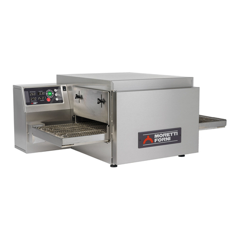
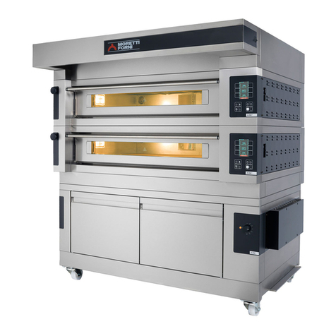
Moretti Forni NEAPOLIS Series User manual

NEAPOLIS
Forno elettrico
Electric oven
Four electrique
Elektrische Ofen
Horno Electrico
Manuale di istruzioni
Instructions manual
Manuel d’instructions
Bedienungsanleitung
Manual instrucciones
Numeri di matricola / Serial numbers :
Cod.733 317
Ver.: A 1

UK/1
INDEX
01 TECHNICAL DATA
2
02 INSTALLATION
2
03 OPERATION
4
04 ROUTINE MAINTENANCE
7
05 SPECIAL MAINTENANCE
9
06 SPARE PARTS CATALOGUE
10
Note:
This manual is printed in five different languages. Original instructions in Italian and translations of the original instructions in English, French, German
and Spanish.
For better clarity and reading this manual, it could be provided in several separate parts and can be sent by mail by contacting the Manufacturer.
WARRANTY
Standards and rules
Warranty only covers the replacement free to factory of pieces eventually broken or damaged because of faulty materials or manufacture. Warranty does
not cover any damage caused by third party transport or due to incorrect installation or maintenance, to carelessness or negligence in usage, or
to tampering by third parties. Glass components, covers, bulbs, refractory surfaces/biscuitware/granite and whatever depends on normal wear
and deterioration of both oven and accessories are not covered by warranty; nor does it cover labour costs involved in replacing pieces covered
by warranty.
Warranty ends in case of non-compliance with payments and for any elements that may be repaired, modified or disassembled, even in part, without prior
written consent. For technical service during the warranty period, please send a written request to the local authorised dealer or directly to the Sales
Department.
WARNING
This word indicates a danger, and will be employed every time the safety of the operator might be involved.
NOTE
- This word indicates the need for caution, and will be employed to call attention to operations of primary importance for correct and long-term operation
of the appliance.
DEAR CUSTOMER
Before using the oven, please read this user manual.
For the safety of the operator, the appliance safety devices should always be maintained in a proper state of efficiency.
This user manual intends to illustrate use and maintenance of the unit. For this reason, the operator is advised to follow the instructions given below.
WARNING!
1. The following instructions are provided for your safety.
2. Please read them carefully before installing and using the appliance.
3. Keep this user manual in a safe place for future consultation by the operators.
4. Installation must be carried out in accordance with the Manufacturer’s instructions by qualified and licensed staff.
5. This oven must only be employed for the purposes for which it was designed, that is to say to cook pizza and similar products. It is
prohibited to bake products containing alcohol. Any other use can be classed as unintended use.
6. The appliance is for institutional use only, and must only be operated by a qualified professional user who has been trained to use it. The
appliance is not intended for use by people (including children) with reduced physical, sensory or mental capabilities or who lack experience
or training. Children should be supervised to ensure they do not play with the appliance. Children should be supervised to ensure they do
not play with the appliance.
7. When carrying out repairs, always contact one of the Manufacturer’s authorised service centres and request that original spare parts be
used.
8. Failure to comply with the above may compromise the safety of the appliance.
9. In the event of breakdown or malfunction always disconnect the oven, and do not attempt to make adjustments or repairs yourself.
10. Should the appliance be sold or transferred to another owner, or should the current owner change his premises and wish to install the
appliance elsewhere, always ensure that this manual remains with the appliance, so that it can be consulted by the new owner and/or the
person carrying out installation.
11. In the interests of risk prevention, if the connection cable is damaged in any way, it must be replaced by a technical assistance service
approved by the manufacturer.
12. During installation, should there be any disturbance to equipment sharing the same power supply source, make sure that the impedence is
suitable at the interface point and that the service current capacity is correctly sized for appliance emissions to conform to EN 61000-3-11
and EN 61000-3-12 standards and subsequent modifications.

UK2
1 TECHNICAL SPECIFICATIONS
1.1 DESCRIPTION OF THE APPLIANCE
The appliance comprises several units positioned one on top of the
other:
- Baking chamber(s) complete with hood
- Leavening Compartment.
The baking chamber has an electronic temperature control and is
equipped with a safety thermostat; internally the chamber is made of
refractory material.
The leavening compartment is comprised of a steel structure which is
panelled, has tray holder guides and is fitted with a thermostat for
heating.
1.2 APPLIED DIRECTIVES
This equipment conforms to the following Directives:
- Low Voltage Directive2014/35/EU (pursuant to 2006/95/EC)
- Directive EMC 2014/30/EU (pursuant to 2004/108/C E)
1.3 WORKPLACES
The appliances are programmed by the operator using the control
switchboards on the front of the appliances themselves, and they must
be attended to while in operation.
The doors giving access to the leavening compartment are located at
the front of the appliance.
1.4 MODELS
The following models are available:
- NEAPOLIS
1.5 WORKING DIMENSIONS AND WEIGHTS (See tab.)
1.6 TECHNICAL DATA (See tab.)
1.7 IDENTIFICATION
When communicating with the manufacturer or service centre, always
give the appliance SERIAL NUMBER, which can be found on the
rating plate, fixed in the position indicated in figure 1.
1.8 LABELLING
The appliance is provided with safety warning labels at the points
indicated in figure 2.
WARNING! On the equipment surface there is a burn risk due
to high temperature elements. For any intervention or action wait for
the appliance to cool to room temperature and always use suitable
personal protective equipment (gloves, goggles…).
WARNING! Presence of dangerous voltage. Before
performing any maintenance operation, disconnect the power supply by
turning off the switches fitted on the outside of the oven and/or the
leavening compartment and wait for the appliance to cool to room
temperature. Always use suitable protective equipment (gloves,
goggles... ).
1.9 ACCESSORIES
The appliances are equipped with the following accessories:
Model Accessories
NEAPOLIS
static oven EXTRACTOR
HEATED LEAVENING COMPARTMENT
UNHEATED LEAVENING COMPARTMENT
If the stand is not supplied by the manufacturer, it must guarantee
proper stability for the appliance under any condition.
1.10 NOISE
This appliance is a technical work tool and normally, the noise level
threshold at the operator station does not exceed 70 dB (A).
2 INSTALLATION
2.1 TRANSPORT
The appliance is normally delivered dismantled on wooden pallets
using ground transport (fig. 3).
The single parts are protected by plastic film or in cardboard boxes.
2.2 UNLOADING
NOTE: On receiving the appliance it is advisable to check its
conditions and quality.
NOTE: If the control panel of the THERMO-REGULATED
leavening compartment is on the control panel of the oven, thus, if
the oven and the compartment must be split, proceed as follows:
**remove the right side panel of the oven (figure 5 item H)
- Disconnect the oven terminal board from the compartment terminal
board (figure 5A items I and L)
- Open the compartment doors, remove the tray holder guides, remove
the bulb thermostat protection cover (figure 5A item N) and remove the
safety bulb thermostat from its seat (figure 5A item M)
- At the end of the installation, perform the above operations in reverse
order to reassemble.
WARNING!Use suitable lifting equipment.
Lift the equipment using only and exclusively the points indicated
in figure 4B; if necessary, position the lifting hooks (figure 4A item
F), but first remove the two side panels of the baking chamber
(figure 5 item H) and then assemble the 4 hooks each with 6
fastening screws as shown in figure 4A. If necessary, hook the
lifting device in a different way from the 4 upper hook holes, use
the 2 long cross bars (code 72016150 in tubular steel pipe
60x30x2mm L = 3mt, provided in the lifting kit), inserted as shown
in figure 4C position D or E depending on the need.
At the end of the operation, remove the 4 lifting hooks and
assemble the 2 side panels (figure 5 item). H)
2.2.1 BAKING CHAMBER TILTING
If it were necessary, tilt the oven to pass through a passage of at least
68cm, proceed as follows:
NOTE: The Biscuit-ware baking surface is made of an
excellent material for baking, but it is fragile so it must always be
handled with great care; if the baking chamber must be tilted
during handling, first the Biscuit-ware baking surface must be
removed, marking the position of each biscuit-ware so that they
can be repositioned in the right position at the end of the
installation.
- Remove in the following order: (see for reference figure 4A) the front
Hood (G), side panels (figure 5 item H) if present, the upper
protection covers (H), the front wall (I) unscrewing also the screws
inside the oven mouth, the internal steam duct (L), the rear panel
(A), and the rear wall (M).
- Position the lifting hooks (Fig. 4A item. F) and bend the oven to its
side in order to move it, once the crossing has been carried out,
perform the reverse operations for reassembly,
2.3 ENVIRONMENTAL SPECIFICATIONS
To ensure that the oven operates properly, it is advisable to comply
with the following limits:
Working temperature:+5°C÷+40°C
Relative humidity: 15% - 95%
POSITIONING, ASSEMBLING AND MAINTENANCE AREAS
WARNING! When positioning, assembling and installing
the oven, the following specifications have to be complied with:
- Laws and standards in force regarding the installation of
electrical appliances.
- Directives and instructions issued by the electricity supply utility
company
- Local building and fire-prevention laws.
- Accident prevention regulations.
- Regulations in force issued by local state Electric Quality
Assurance Corporation.

UK3
WARNING!The appliance must be installed on a firm and
levelled surface, perfectly leveled. The equipment must never come
into contact with flammable or combustible materials.
NOTE: Position the oven in such a way that there are no
drafts in the vicinity of the cooking chamber doors, as this may
disturb cooking.
The individual modules chosen to set the oven must be placed on top of
one another as shown in fig. 5, slotting the relevant feet of each module
into the openings of the module below (item.A - fig.5).
The oven must also be positioned in a well-aired room, at a distance of
at least 10 cm from the left side wall and from the rear wall, and of 50
cm from the right side wall (Fig.6). This distance of 50 cm is essential
in order to guarantee access during maintenance operations and good
ventilation of components
Take into account that for certain cleaning/maintenance operations, the
distance needs to be greater than stated here and therefore, consider the
possibility to be able to move the oven for the purpose of carrying out
these operations.
The basic perimeter protection cover of the leavening compartment is
provided disassembled to allow easy handling of the wheeled
compartment; therefore, the 2 rear and front cover protections (figure 5
item B and C) must be assembled first, making sure that their colours
correspond to those of the area on which they are assembled.
- Position the rear protection cover (figure 5 item.B) into its seat and
fasten it with 2 screws per side to the special brackets (figure 5 item.E),
then screw the two rear screws provided (figure 5 item P ).
- Brake the 2 wheels of the compartment, open the doors (figure 5 item
L), loosen the 4 screws (figure 5 item R) and close again the doors;
position the front protection cover (figure 5 item C) on its seat on the
RIGHT SIDE and INSERT IT FRONTALLY INTO THE SLOT
(figure 5 item D) using a thin blade, until the protection cover is in
place, then fasten it to the appropriate brackets (figure 5 item N), with
the 3 screws placed on the right side and 2 screws on the left side, then
tighten the 4 screws (figure 5 item R).
- Subsequently, assemble the 2 side balancing protection covers (figure
5 item F) using for each of them the two screws (figure 5 item G), the
side protection covers are of balancing type to facilitate cleaning and
allow access to the 2 front wheels whose brake must be activated once
the oven has been positioned. - See section 2.5.2.2 for electrical
connection.
2.5 CONNECTIONS
2.5.1 VAPOUR EXHAUST CONNECTION
WARNING!Connection of the steam exhaust must only be
carried out by specialised personnel.
The connection provided with the oven (figure7 item.A) must be
positioned in its seat in the upper part of the oven, as shown in figure7.
NOTE:Connect this connection to a chimney or to the outside
by using a recommended pipe with a diameter of 200mm
(minimum 150mm, in this case connected it, through a suitable
adapter placed in its upper part, to the connection with diameter of
200mm).
The pipe (figure 7 item B) must be positioned inside the connection
(figure 7 item A). Any extensions must be fitted so that the top pipes
slot into the bottom ones.
The draught can be adjusted thanks to the manual valve located
under the hood (see paragraph 3.4), normally it must be all open,
but in the presence of a chimney with a lot of draught, it must be
adjusted by closing it until the ideal balance is found.
2.5.2 ELECTRICAL CONNECTION
WARNING!Electrical connection must only be carried out
by specialised personnel, in compliance with current local state
Electric Quality Assurance Corporation requirements.
Before starting the connection procedure, check that the earthing
system is provided in accordance with European EN standards.
Before starting the connection procedure, check that the main
power switch for the supply to which the oven is to be connected
has been turned to the “off” position.
The rating plate contains all the information necessary for proper
connection.
2.5.2.1 ELECTRICAL CONNECTION OF THE BAKING
CHAMBER
WARNING! For each baking element, it is necessary to fit
a main four-pole switch with fuses or an automatic switch suitable
for the values shown on the plate, to allow the appliance to be
disconnected from the mains and that provide full disconnection
under overvoltage category III conditions.
NOTE:The device selected should be in the immediate vicinity
of the appliance and within easy access.
The baking chamber is delivered with the required voltage indicated on
the rating plate (fig.1).
To carry out the electrical connection, remove the protective cover
located on the rear side of the baking chamber (fig. 8 item A). The
connection cable must be provided by the installer. A standard plug
must be installed for the electrical power connection.
Insert a cable with an adequate cross-section (see technical data) into
the cable raceway provided (fig.8 item B) and connect it to the terminal
board as shown in figures 9 and 10, respectively.
Moreover, these appliances must be connected to the unipotential
system: a terminal is provided for this purpose at the back of the
appliance (Fig. 8 item C). It is marked with the following symbol
TERMINAL FOR THE UNIPOTENTIAL SYSTEM.
When the connection has been completed, check that the supply
voltage, with the appliance running, does not differ from the rated
value by more than ±10%.
WARNING! The flexible wire for connection to the power
supply must have characteristics at least equal to the model, with
rubber insulation HO7RN-F and it must have a rated section
suited to the maximum absorption (see technical data).
NOTE: **CHECK THAT THE POWER SUPPLY PHASES
ARE CORRECT AND EFFECTIVE, CHECK THE
CORRECTNESS OF THE CURRENT DRAWN.
2.5.2.2. LEAVENING COMPARTMENT ELECTRICAL
CONNECTION
The control panel of the leavening compartment is placed on the
control panel of the oven, so the oven and compartment must be
connected, to do this proceed as follows:
- Remove the right side panel of the oven (figure 5 item H)
- Connect the terminal board of the oven to the terminal board of the
leavening compartment (figure 5A items I and L)
- Open the compartment doors, remove the tray holder guides placed
on the right, position the thermostat bulb in its seat (figure 5A item M)
and reassemble the thermostat bulb protection cover (figure 5A item N)
- Reassemble the right side panel of the oven (figure 5 item.H) and
replace the tray holder guides
WARNING! The compartment must be fitted with a main
two-pole switch with fuses or an automatic switch suitable for the
values shown on the plate.
NOTE:The device selected should be in the immediate vicinity
of the appliance and within easy access.
The leavening compartment is delivered with a voltage of 230V 1N
50/60 Hz, as indicated on the rating plate (fig.1).
To carry out electrical connection, remove the protective cover located
on the rear side of the compartment (fig.8 item D).
The connection cable must be supplied by the installer.
When connecting to the power mains, it is necessary to fit a plug that
complies with the standards and regulations in force.
Insert a cable with a suitable cross-section (see technical data) into the
relevant cable raceway (Fig. 8 item E) and connect it to the terminal
board, as illustrated in figure 11.
When the connection has been completed, check that the supply
voltage, with the appliance running, does not differ from the rated
value by more than ±10%.
WARNING! The flexible wire for connection to the power
supply must have characteristics at least equal to the model, with
rubber insulation HO7RN-F and it must have a rated section
suited to the maximum absorption (see technical data).

UK4
WARNING! It is essential that the appliance be properly
earthed.
A special earth terminal has been provided for this purpose on the
connection terminal board (fig. 9-10-11). It is marked with the
earth symbol and the earth wire must be connected to it.
Moreover, these appliances must be connected to the unipotential
system: a terminal is provided for this purpose at the back of the
appliance (Fig. 8 item F). It is marked with the following symbol
TERMINAL FOR THE UNIPOTENTIAL SYSTEM.
2.5.2.3 EXTRACTOR ASSEMBLY (optional)
Assemble the extractor (figure 7 item E), adjust the draft using the
guillotine valve (figure7 item. F) closing the openings until the ideal
balance is found, THIS IN ORDER NOT TO TAKE AWAY TOO
MUCH HEAT FROM THE BAKING CHAMBER. Finally,
assemble the extractor cover.
3 OPERATION
3.1 PRELIMINARY CONTROL OPERATIONS
WARNING! Before commencing start-up and
programming of the oven, always check that:
- all the electrical and earthing connections have been properly
made.
- all vapour exhaust connections have been properly made.
NOTE: At the end of the installation, before turning on the
oven, place the biscuit-wares in such a way that in the centre there
is the minimum space between them.
All control operations must be carried out by specialised
technicians holding a valid license.
WARNING!
- The oven must always be under surveillance when in operation.
- During operation, the oven surfaces, and in particular the glass,
become hot, so make sure not to touch them in order to prevent
scalding.
- When opening the door make sure you stand at a safe distance
from any hot steam that may come out of the baking chamber.
- Never allow unauthorised persons to approach the oven.
For more even results, we recommend avoiding the use of temperatures
above those recommended for the type of product being baked.
3.2 PUTTING THE BAKING CHAMBER INTO SERVICE
A QR Code is located on the control panel showing the Video
TUTORIAL with the explanation of the functions of the electronic
control unit, it is recommended to watch it before using the
equipment.
Two control panels are located on the front right hand side of the
baking chamber, as illustrated in figure 12.
1. Main switch (ON/OFF)
2. Safety thermostat (Reset)
3. Temperature regulator (+up/-down)
4. Set temperature display (Set Point °C)
5. Ceiling power regulator
6. Ceiling power regulator display
7. Floor power regulator
8. Floor power regulator display
9. Start/Stop heating elements button
10. Economy/Power.
11. Baking chamber on/off button (light)
12. Baking chamber internal temperature display
13. Manual/Cleaning
14. P button (programs).
15. Timer button
NOTE: The electronic controls allow more precise and rapid
regulation of the oven. However, they are by nature more delicate
than traditional ones.
To ensure that they remain in a proper state of operation it is
recommended that the buttons on the electronic control panel be
activated by pressing lightly with one finger, avoiding excessive
pressure or impact.
a) Turn the main switch (Fig. 12 item 1) on the central control panel
to ON. Both the switch itself and the electronic panel on the right
will light up.
The control unit allows you to use the oven in “MANUAL” mode
or to use the “PROGRAMS” by recalling one of the baking
programs stored to memory.
The "M" (manual figure 12 item 13) and "P" (programs figure 12
item 14) buttons are located on the pyrometer; by pressing them
the passage from one mode to the other is enabled. The relevant
LED on each button shows which of the two modes has been
selected at all times.
When the oven is switched on, the pyrometer returns to the
previous setting from the last time it was switched off (the LED
light indicates whether this is “Manual” or “Programs” mode).
3.2.1 SWITCHING ON FOR THE FIRST TIME
When starting up the equipment for the first time or after a long period
of disuse, it is essential to carry out the heating procedure as follows:
- Set the temperature to 100°C (212°F) and leave the chamber to
operate for about 1 hour. If there is a great deal of steam inside the
chamber, open the door for a few minutes to let out the steam and
then close it again.
- Increase the temperature to 200°C (392°F) and leave the chamber
operating for about 2 hours. If there is a great deal of steam inside the
chamber, open the door for a few minutes to let out the steam and
then close it again.
- Increase the temperature to 300°C (572°F) and leave the chamber
operating for about 1 hour. If there is a great deal of steam inside the
chamber, open the door for a few minutes to let out the steam and
then close it again.
- Increase the temperature to 400°C (752°F) and leave the chamber
operating for about 1 hour. If there is a great deal of steam inside the
chamber, open the door for a few minutes to let out the steam and
then close it again.
- Increase the temperature to 450°C (842°F) and leave the chamber
operating for about 1 hour. If there is a great deal of steam inside the
chamber, open the door for a few minutes to let out the steam and
then close it again.
- Increase the temperature to 510°C (950°F) and leave the chamber
operating for about 1 hour. If there is a great deal of steam inside the
chamber, open the door for a few minutes to let out the steam and
then close it again.
- Wait for the temperature to cool to ambient levels before switching
the oven on again. If there is a great deal of steam inside the
chamber, open the door to let it out
This procedure serves to remove any moisture built up inside the oven
during the production, storage and shipping stages.
NOTE: It is possible for the appliance to give off unpleasant
odours during the operations mentioned above. Ventilate the area.
A white patina in the baking chamber may form, both on the first
and subsequent start up, if necessary remove it with the brush;
when the oven is cold, with a damp cloth, remove this patina from
the 2 glass covers so not to loose brightness in the baking chamber.
The patina formed on the cast iron part of the oven mouth must be
removed exclusively using a damp cloth when the oven is cold so as
not to damage its door.
WARNING!Only use the oven for baking for the first time
after carrying out the above procedures, which are absolutely
essential for perfect operation.
WARNING! Never bake any items the first time that the
equipment is switched on or when it is switched on after a long
period of disuse.
NOTE: When switching on the oven again, to increase the
duration of the component parts (refractory surfaces), it is
necessary to prevent heating too suddenly. Each time before
reaching the baking set point, keep the oven at a temperature
between 120°C (250°F) and 160°C (320°F) for at least 40 minutes.
3.2.2 STARTING UP THE BAKING CHAMBER IN MANUAL
MODE
b) Set the desired baking temperature by pressing the buttons (figure
12 item 3). The value will be shown on the right hand luminous
display (fig.12 item 4).
c) Adjust the ceiling (figure 12 item 5) and floor (figure 12 item 7)
power values. These values vary from 0 (power disconnected) up
to 9 (maximum power) and appear on luminous displays (fig.12
item 6) and (fig.12 item 8), respectively.

UK5
The use of the ceiling and floor heating elements, is highlighted by
a dot in the lower right corner of the display (figure 12 item 6) and
(figure 12 item 8).
The turning on and off of the dot indicate respectively the power
consumption or non-consumption of the heating elements.
Separate adjustment of the ceiling and floor temperatures makes
use of the oven much more flexible, allowing for more customised
baking.
d) Turn on the chamber power supply by using the power button
(figure 12 item 9): a red LED lights up.in the upper right corner.
e) When the temperature inside the baking chamber (fig.17 item 12)
reaches the set temperature (4), the power supply will cut out and
the indicator led (fig.17 item 6 and fig.17 item 8) will turn off.
When the temperature inside the baking chamber drops below the
set value (fig.17 item 12), the power supply will automatically cut
in again and the LED will light up once more.
f) The oven control system is equipped with an economy function,
which can be switched on either automatically or manually.
f.1) Automatic enabling of the economy function
When the sum of the values set for the ceiling (fig.12 item 6) and the
floor (fig.12 item 8) is equal to or less than 9, the economy function is
enabled automatically and a red LED in the top right hand corner of the
button lights up (fig.12 item 10).
This means that the heating elements in the ceiling and floor are never
fed simultaneously, and therefore the oven uses approximately half the
amount of power.
f.2) Manual enabling of the economy function
When the sum of the values set for the ceiling (fig.12 item 6) and the
floor (fig.12 item 8) is higher than 9, the heating elements are fed
according to the set values.
In this case it is possible to enable the economy function manually by
pushing the Economy/Power button (fig.12 item 10).
The red LED in the top right hand corner of the button will start to
flash and the values set for the ceiling (fig. 12 item 6) and the floor (fig.
12 item 8) will be reduced proportionally to the values set until they
add up to a value equal to or less than 9. The oven will thus operate
with a power consumption reduced approximately to half. The
economy function is disabled merely by pressing the Economy/Power
button (fig. 12 item 10) again: the red LED will go out and the values
originally set for the ceiling (fig. 12 item 6) and the floor (fig. 12 item
8) will be restored.
If the economy function has already been enabled manually (the red
LED on button 10 is flashing) and adjustments are made to the ceiling
(fig. 12 item 5) and floor (fig. 12 item 7) regulator buttons, the
economy function will once again adjust the values automatically until
the sum is once again equal to or less than 9.
When the manual economy function is disabled, the values displayed
will be the ones set during the last adjustment.
Manual enabling of the economy function is extremely useful during
periods of little work or pause, when maximum power is not required
but the oven needs to be kept at a certain temperature so as to be ready
to return quickly to normal work.
NOTE:The “Economy” function is switched off when passing
from “Manual” to “Program” and vice versa; it is also switched off
when passing from one program to another and/or when “saving”
a program.
When baking, if passing to the program display or to editing the
program being used, the Economy function is momentarily
disabled and then re-enabled automatically when the program
returns to viewing the temperature of the oven.
g) The baking chamber temperature adjustment (Fig. 12 item 4) is set
for a maximum temperature of 510°C (950°F). If, due to an
anomaly, this threshold is exceeded, the safety thermostat (fig. 12
item 2) intervenes to block oven operation by switching it off.
All the indicator lights on the lower control panel will start to
flash, signalling an alarm. Wait until the oven cools down.
Unscrew the cap of the safety thermostat (figure 12 item 2), press
the button below which will reset the thermostat, the lower panel
will stop flashing and the oven will restart normally.
Replace the protective cap (Fig. 12 item 2) over the safety
thermostat to prevent this instrument from deteriorating and
preventing the oven from operating properly.
WARNING! If this operation is carried out without
waiting for the oven to cool down, the manual safety
thermostat will not allow the oven to be reset.
If the problem continues to arise, please call the technical
service department.
h) The “light” button (fig.12 item 11) is used to switch the lighting
inside the baking chamber on and off.
i) To turn the oven off, simply turn off the main switch (fig. 12 item
1).
When the oven is turned on again the control panel will be in the same
state as when it was last turned off.
l) POWER function
If necessary immediately set the power of the oven heating elements to
the maximum power value by holding down the ECONOMY/POWER
button for a few seconds; the ceiling and floor power values reach the 9
maximum value set, and the red LED of the button (figure 12 item 10)
will start to flash. Press again the ECONOMY/POWER button to
disable the POWER function and set the power values to the same
values of the previous setting
By manually increasing the power values to 9 and 9, the LED of the
button (figure 12 item 10) lights up steadily to indicate that the
POWER function is enabled. Decrease at least one of the two power
values to disable the POWER function, the LED of the button turns off.
NOTE: The “Power” function is switched off when passing
from “Manual” to “Program” and vice versa; it is also switched off
when passing from one program to another and/or when “saving”
a program.
m) CLEANING function
NOTE: The door must be securely closed during the cleaning
At the end, it is recommended to open the valve to allow steam to
be discharged.
This function can be used to eliminate cooking residue on the internal
walls of the oven by means of carbonisation. When this function is
selected, a program pre-set to very high temperatures is activated for a
factory-set period of time. When this program has completed and the
oven is again at room temperature, it is sufficient to remove the charred
residues with a brush or vacuum cleaner suitable for the task.
To enable the cleaning function, press and hold down the
MANUAL/CLEANING button for a few seconds (figure 12 item
13), the display will show "cln run" and the chamber lighting
system, if enabled, will turn off automatically.
At the end of the program, the oven will enter its STOP mode,
switching off the power supply to the heating elements and a buzzer
sound will warn the operator that the cleaning operation has ended.
Press “OK” to quit and proceed to switch off the appliance ass
described in 3.9.
Press the START/STOP button (figure 12 item 9) to end the
Cleaning program
NOTE:It is possible to enable the CLEANING function at the
end of the work day even after activating the clock for the daily
programmed turn on as described in 3.7.5. At the end of the
cleaning cycle, in automatic mode, the display of the turn on time
will be shown again.
3.2.3 STARTING THE BAKING CHAMBER IN PROGRAM
MODE
It is possible to store 20 different baking programs from the control
panel; for each program, it is possible to enter a Set Point temperature,
a ceiling power level, a floor power value and the baking Timer. Once
a general program has been stored, when this is recalled, you will
automatically find the previously set baking settings
STORING A PROGRAM
1) Press the “P” button (figure 12 item14). The display on the left
will show the number of the last program used; the displays on
the right will show the set point temperature and the ceiling and
floor power set for this program (pressing the “P” button again
will pass on to the next program, and so on, until you have
scrolled through all 20 programs in the memory).
2) Once positioned on the required program No. (no. 5, for
example), follow the procedure in points 3.2a and 3.2c to change
the temperature setting and the power levels for the “ceiling” and
“floor”
3) Hold down the “P” button (fig. 12 item 14) for at least 2 seconds
and until the buzzer makes a brief sound; this will store the new
program in the memory.
4) It is also possible to associate the “baking Timer” to a program; to
set the timer, press the Timer button (fig. 12 item 15) and the
display on the left will read “OFF” while the right-hand display
will show the baking time in: MINUTES “comma” SECONDS.
This time can be changed using the buttons under the display (up
and down arrows). By pressing the Timer button (figure 12
item15) for the second time it is possible to set the turn on time.

UK6
By pressing the Timer button for the third time it is possible to
return to the desired program.
5) Hold down the “P” button (fig. 12 item 14) for at least 2 seconds,
until a BEEP sound is heard; this will store the new program,
baking timer included, in the memory.
NOTE: When a general program is started, if a “Baking
time” is associated to this program, to start the timer, proceed as
for the “Manual” mode described in point 3.7.4.
USING A PROGRAM
1) Press the “P” button (fig. 12 item 14) several times until the
required baking program is displayed.
2) Turn on the chamber power supply by using the power button
(figure 12 item 9): a red LED lights up.in the upper right corner.
NOTA:The left display no longer shows the program number
but the actual temperature of the oven, which flashes until it
reaches the set point temperature set. ( 4 "Beeps" indicate that the
set point temperature was reached).
The green LED beside the “P” button will remain lit to show that one
of the programs is being used.
To see the number of the program in use while it is running, press the
“P” button. Press “Start” to return to the normal display.
3.2.4 PRE-SET PROGRAMS:
P01 RISE IN TEMPERATURE / LOW WORK LOAD
Program P01 is the program pre-configured by the Factory to
optimize the temperature rise of the oven at a pre-set operating
temperature for Pizza Napoletana. Enable program P01 as described
in 3.2.3. At the beginning of the program, the displays of the power
values show the letter "H" to indicate that the oven is in the heating
stage ("Heating") and the power values cannot be changed. Only
when a temperature set by the Factory is reached, the letters "H" are
replaced by the power values set by the program.
P02 MEDIUM WORK LOAD
P02 program is the factory-configured program for medium work
loads at a pre-set operating temperature suitable for Pizza
Napoletana. Enable program P02 as described in 3.2.3.
FROM P03 TO P20 - GENERIC PROGRAMS
Programs from P03 to P20 are factory pre-configured programs for
operating temperatures lower than the one for Pizza Napoletana.
Enable the desired program as described in 3.2.3.
NOTE: All programs can be modified as described in 3.2.3.
Program P01 is the only program optimized for temperature rise,
whose powers at the beginning of the program cannot be set (the
display Figure 12 items 6 and 8 show “H”)
3.3 STARTING UP THE EXTRACTOR HOOD
The hood has a powerful motor to extract the cooking vapours. The
main circuit breaker of the extractor is located on the front of the
control panel (figure 13B item 4).
a) Enable the switch to start the extraction.
b) To switch off the extractor, move the switch (fig. 13B item 4) in
the zero position.
3.4 DISCHARGING VAPOUR
The vapours that form inside the baking chamber exit from the door
and are collected by the front hood, which conveys them to the vapour
exhaust connection. The valve that allows to correctly adjust the
draught (figure 14) is located under the front hood. This valve is held in
position through the knob A, if held in O position, the valve will be all
OPEN and therefore the draught will have the maximum value, if held
in C position the valve will be all CLOSED and therefore the draught
will have the minimum value, the intermediate positions accordingly
will proportionally adjust the draught.
Normally, the valve must be all open, but in the presence of a chimney
with a lot of draught, it must be adjusted by closing it up to find the
ideal balance, this in order not to take away too much heat from the
baking chamber.
WARNING! The valve and the knob A are heated during
the work, so the adjustment must be carried out when the oven is
cold, if in exceptional cases, the oven valve should be adjusted, this
operation must be carried out by wearing special gloves for high
temperatures in order to avoid burns.
3.5 DESCRIPTION OF THE OVEN
- Turn off the lights and securely close the DOOR
- Set the oven approximately between 430°C and 485°C with the
Ceiling set to 8 and Floor about to 3 and turn on the oven.
- Once the set temperature is reached, remove the door by holding it
exclusively by the provided handle (figure 7 item C) and place it in the
appropriate holder (figure 7 item D)
WARNING! DOOR AND DOOR HOLDER REACH
HIGH TEMPERATURES, THEREFORE PAY GREAT
ATTENTION NOT TO TOUCH THEM IN ORDER NOT TO
GET BURNED; STORE THEM IN A SAFE PLACE THAT
CANNOT BE REACHED BY THIRD PARTIES (E. G.
CHILDREN, ETC.) AND NEVER NEAR COMBUSTIBLE
MATERIALS.
The oven is manufactured to be used with a baking system similar to
that of the wood-burning oven, so the warmest area of the baking
chamber is the rear one, in the central area the heat reaches medium
values, while the front area, where ambient air goes in, is the least hot
area; for example, initially use the central area and then the rear area
for pizza baking while the front area must be used for what are called
"mouth baking" such as "calzoni", etc..
- Begin baking and when the amount of work reaches a MEDIUM
level, set the Floor to 5/6
- When the load work increases, increase the settings of the Ceiling and
Floor, if it is necessary set them to 9 and to 9 respectively (if the
ECONOMY/POWER is pressed and held down for a few seconds the
oven reaches the maximum temperature as the Ceiling and Floor were
set to 9 and to 9 respectively
After the first baking, check if the temperature is suitable for the dough
to be baked, such a dough must have the right level of hydration and
leavening in order to be properly baked (if the hydration is poor or if
too much flour is put on the shovel, the lower part of pizza will burn
more easily); decrease or increase the temperature accordingly (if you
wish to quickly raise the temperature and minimize electrical
consumption, securely close the door of the oven until the new set
point is reached.
NOTE: The oven has electrical heating elements (resistors)
built-in the ceiling and floor refractory which reach very high
temperatures. IT IS STRICTLY FORBIDDEN TO WET THE
BAKING SURFACE EVEN WITH A DAMP CLOTH, BECAUSE
THE THERMAL SHOCK IRREPARABLY DAMAGES THE
BISCUIT-WARE; if it is necessary to clean the surface, USE
EXCLUSIVELY THE FILTER PRESS CAKES For cleaning
during the work stages, use a soft brush of adequate height. Be
careful not to hit the side/rear refractories, any impact could break
them; if this happens, the functionality of the oven is not
compromised; any cracks in Biscuit-wares may occur but they do
not compromise the functionality of the oven.
- In the event of long work breaks it is recommended to securely
CLOSE the door of the oven and to press the Economy button and turn
off the lights; the oven consumption will be reduced to the minimum
value and it will be immediately ready to bake again. At the end of the
work, turn off the oven, leave it without the door for about 15 minutes
to allow the residual internal humidity to drain off and then place back
the door WELL CLOSED.
WARNING! In the event that unintentionally the products
during the baking stage catch fire (for example because they
contain oils or fats), close the door and seal it to smother the
flames, do not use water inside the baking chamber.
NOTE: The door, when needed, MUST BE PERFECTLY
CLOSED, TO DO SO POSITION IT ON THE CAST IRON PART
OF THE OVEN MOUTH (figure 7 item C), THE DOOR MUST
NEVER BE LEFT PARTIALLY OPEN TO PREVENT
OVERHEATING AND CRAKCS ON THE GRANITE FRONT
SURFACE Be careful not to hit / scratch the granite surface with
trolleys, shovels, etc. in order not to damage it.
3.6 STARTING UP THE LEAVENING COMPARTMENT
The control panel of the leavening compartment is the one located on
the left, below the front sliding door of the baking chamber, as shown
in figure 13A (if the hood extractor is present, refer to figure 13B).
1. Indicator light (ON/OFF).
2. On/off circuit breaker for internal lighting (to be enabled the
thermostat must be activated).
3. On/off and regulation thermostat.
a) Turn the leavening compartment on by turning the thermostat
(item 3), the indicator light will come on (item 2).
b) Set the temperature required, up to a maximum 65°C (150°F).

UK7
c) To turn the leavening compartment off, turn the thermostat (item
3) back to zero.
WARNING! Avoid contact with the heating element
(resistors) located inside the leavening compartment to avoid
burns.
3.7 STARTING UP THE ELECTRONIC CONTROL UNIT
WITH TIMER
The electronic control panel is equipped with the "Timer" button
(figure 12 item 15).
The control unit enables 3 baking timers to be set (countdown), as well
as the current time and the daily start-up time (fig. 12).
3.7.1 SETTING THE 3 BAKING TIMERS
- When the ”Timer” button (fig. 12 item 15) is pressed once, the
message “OFF 000” will be shown on the display (fig. 12 items 4
and 12) and the ceiling display will read “1” (fig. 12 item 6). This
indicates that it is possible to set the first baking timer, in minutes,
using the “Up” and “Down” buttons (Fig. 12 item 3).
- When the ”Timer” button (fig. 12 item 15) is pressed again, the
second baking timer will be shown on the ceiling display (fig. 12
item 6), and it can be set in the same way.
- When the button is pressed a third time, the third baking timer can be
set.
3.7.2 PROGRAMMING THE CURRENT TIME
- When the ”Timer” button (fig. 12 item 15) is pressed a fourth time,
the message “h 00 00” (or a generic time) will be shown on the
display (fig. 12 items 4 and 12); the first two figures refer to the
hour, the second to the minutes.
- Press the “up” button to set the hours, and the “down” button to set
the minutes (fig. 12 item 3).
3.7.3 PROGRAMMING THE START-UP TIME
- When the ”Timer” button (fig. 17 item 15) is pressed a fifth time, the
message “o 00 00” (or a generic time) will be shown on the display
(fig. 12 items 4 and 12); the first two figures refer to the hour, the
second to the minutes.
- Press the “up” button to set the start-up hour, and the “down” button
to set the minutes (fig. 12 item 3).
- Press the ”Timer” button (fig. 12 item 15) for the sixth time to exit the
timer function.
NOTE: If the timer is not programmed within ten seconds of
entering this function, the control unit will automatically exit the
function and the temperature and set point will be shown once
again on the displays (fig. 12 items 4 and 12).
3.7.4 STARTING THE BAKING TIMER
MANUAL MODE
- In order to start one of the three baking timers, access the timer
function, select the timer required and press the “Start/stop” (fig.12
item 9) and the “Timer” buttons simultaneously.
The timer LED (fig. 12 item 15) will start to flash, indicating that
there is a baking timer in operation.
- When the "Timer" button is pressed (fig.12 item 15) the timer in
operation and the time remaining will be displayed.
- As soon as the timer countdown has finished, all the displays will go
out, the timer LED (fig. 12 item 15) will light up and the buzzer will
begin sounding. Press the "Timer" button (fig. 12 item 15) to return
to normal.
PROGRAMS MODE
- To start the baking timer, access the timer function and press the
"Start/Stop" (fig. 12 item 9) and the "Timer" buttons simultaneously.
The timer LED (fig. 12 item 15) will start to flash, indicating that
there is a baking timer in operation.
- When the "Timer" button is pressed (fig.12 item 15) the timer in
operation and the time remaining will be displayed.
- As soon as the timer countdown has finished, all the displays will go
out, the timer LED (fig. 12 item 15) will light up and the buzzer will
begin sounding. Press the "Timer" button (fig. 12 item 15) to return
to normal.
NOTE: The baking timers have no effect on the baking
conditions in the oven.
3.7.5 STARTING THE TIMER FOR DAILY PROGRAMMED
START-UP
- To enable programmed start-up it is necessary to set the temperature
required and the ceiling and floor values, then enter the start-up time
function (press the “Timer” button (fig. 12 item 15) five times in
manual mode or once in programs mode), check the set start-up
time, then press the “Start/Stop” button (fig. 12 item 9) and the
“Timer” button simultaneously.
The timer led (figure 12 item 15) will start flashing indicating that
the power on timer is in operation: the oven will turn off and the
power on time will remain shown on the display (figure 12 items 4
and 12) .
At the time indicated, the oven will start up.
- After the start-up timer has been enabled, press the “Timer” button
(fig. 12 item 15) to see the temperature and set point.
NOTE:To disable the timers and the start-up time before they
come into operation, merely press the “Start/Stop” (fig. 12 item 9)
and “Timer” buttons (fig. 12 item 8) simultaneously.
3.8 CENTIGRADE OR FAHRENHEIT SELECTION
- Pressing and holding down the “light” (fig.12 item.11) and “+ up”
(fig.12 item.3) buttons for about 6 seconds will show the current
setting for the temperature unit of measure (“°C” or “°F” ).
- Holding down the buttons for another 6 seconds will change the
previous setting.
3.9 SHUT DOWN
- Turn off the main circuit breakers of the oven (figure 12 item 1), of
the leavening compartment (figures 13A-13B item 3) and those of
the hood extractor (figure 13B item 4), by placing them on the
ZERO position.
- Disconnect the power supply by turning off the main power switches
outside the appliance.
3.10 INTERNAL BALANCING DEFLECTORS
The baking chamber has 2 balancing deflectors placed on the ceiling of
the baking chamber (figure15 item.A) to minimise the dispersions,
standardise the thermal flows and maintain the right degree of humidity
for the product being baked. If necessary, it is possible to place the
Deflectors in the open position (figure15 item B); to do this, turn the
deflector towards the front by using a pizza shovel, lift it and position it
towards the oven mouth so that it is supported by the two side stops.
4 ROUTINE MAINTENANCE
4.1 PRELIMINARY SAFETY OPERATIONS
WARNING! Before performing any maintenance
operation, disconnect the power supply by turning off the switches
fitted on the outside of the oven and/or the leavening compartment
and wait for the appliance to cool to room temperature. Always use
suitable protective equipment (gloves, goggles... ).
All precautions are of importance to ensure that the oven remains
in a good state, and failure to observe them may result in serious
damage which will not be covered by the warranty and may lead to
hazard exposure
4.2 ROUTINE CLEANING
After carrying out the operations described in point 4.1 above, clean the
appliance as follows:
NOTE: To clean the baking surface, use the CLEANING
FUNCTION by thermo-reduction (point 3.2.2 section M) or use
delicately a suitably long soft brush. IT IS STRICTLY
FORBIDDEN TO WET THE BAKING SURFACE EVEN WITH
A DAMP CLOTH, BECAUSE THIS MAY IRREPARABLY
DAMAGES THE BISCUIT-WARE
NOTE: Be careful not to hit the side/rear refractories, any
impact could break them; if this happens, the functionality of the
oven is not compromised; any cracks in Biscuit-wares may occur
but they do not compromise the functionality of the oven.
A white patina in the baking chamber can commonly be formed,
both at the first and subsequent start up, if necessary remove it
with the brush; when the oven is cold, with a damp cloth, remove
this patina from the 2 bulb glass covers not to loose brightness in
the baking chamber. The patina formed on the cast iron part of the
oven mouth must be removed exclusively using a damp cloth when
the oven is cold so as not to damage its door.

UK8
Every day, at the end of operations and after leaving the appliance to
cool down, carefully remove from all parts of the oven, except from the
biscuit-ware, any residues that might have collected during cooking,
using a damp sponge or cloth and a little soapy water, if necessary.
Rinse and dry the areas, being sure to wipe parts with satin finish in the
direction of the finish.
Carefully clean all accessible parts.
WARNING! Every day, carefully clean off any fat or
grease that may have dripped during cooking as this is a potential
fire hazard.
WARNING! Never clean the appliance with direct jets of
water or with pressurised water jets. Always take care to ensure
that the water or other products use does not come into contact
with electrical parts.
The use of toxic or harmful detergents is strictly prohibited.
NOTE: Do not use solvents, detergents containing aggressive
substances (chlorides, acids, corrosives, abrasives, etc. …) or
equipment that could damage surfaces. Before starting up the
appliance again, make sure that none of the cleaning equipment
has been left inside.
4.3 PERIODS OF INACTIVITY
If the appliance is not to be used for long periods:
- Disconnect it from the power supply.
- Cover it to protect it from dust.
- Ventilate the rooms periodically.
- Clean the appliance before using it again.

UK9
5 SPECIAL MAINTENANCE
5.1 PRELIMINARY SAFETY OPERATIONS
WARNING! All maintenance operations and repairs must
be carried out using suitable accident prevention equipment, by
specialised and properly licensed technicians, approved by the
manufacturer.
Before performing any maintenance operation, disconnect the
power supply by turning off the switches fitted on the outside of the
oven and/or the leavening compartment and wait for the appliance
to cool to room temperature.
All precautions are of importance to ensure that the oven remains
in a good state, and failure to observe them may result in serious
damage which will not be covered by the warranty and may lead to
hazard exposure
WARNING!Some operations, listed here below, need to be
carried out by at least two people.
5.2 GENERAL CLEANING
After carrying out the operations described in point 5.1 above, clean the
appliance as follows.
Regularly clean the appliance in general.
NOTE: To clean the baking surface, use the CLEANING
FUNCTION by thermo-reduction (point 3.2.2 section M) or use
delicately a suitably long soft brush. IT IS STRICTLY
FORBIDDEN TO WET THE BAKING SURFACE EVEN WITH
A DAMP CLOTH, BECAUSE THIS MAY IRREPARABLY
DAMAGES THE BISCUIT-WARE
NOTE: Be careful not to hit the side/rear refractories, any
impact could break them; if this happens, the functionality of the
oven is not compromised; any cracks in Biscuit-wares may occur
but they do not compromise the functionality of the oven.
After leaving the appliance to cool down, carefully remove, from
internal and external parts, except from the biscuit-ware, all the
residues that might have collected during cooking, using a damp
sponge with a little soapy water, if necessary. Rinse and dry the areas,
being sure to wipe parts with satin finish in the direction of the finish.
WARNING!Carefully clean off regularly any fat or grease
that may have dripped during cooking as this is a potential fire
hazard.
WARNING!
Based on the use of the appliance it will be appropriate to remove
periodically the biscuit-ware elements as described in point 5.3.5
and remove from underneath them all the baking residues.
WARNING! Never clean the appliance with direct jets of
water or with pressurised water jets. Always take care to ensure
that the water or other products use does not come into contact
with electrical parts.
The use of toxic or harmful detergents is strictly prohibited.
NOTE: Do not use solvents, detergents containing aggressive
substances (chlorides, acids, corrosives, abrasives, etc. …) or
equipment that could damage surfaces. Before starting up the
appliance again, make sure that none of the cleaning equipment
has been left inside.
5.3 REPLACING PARTS OF THE BAKING CHAMBER
5.3.1 REPLACING THE LIGHT BULB
Given the heavy workload to which the light bulbs are subjected, in
time it may be necessary to replace them.
NOTE: THE NEW BULB MUST BE A HIGH
TEMPERATURE LIGHT BULB AND SHOULD NOT BE
TOUCHED WITH BARE HANDS, BUT WITH GLOVES OR A
CLOTH IN ORDER TO AVOID COMPROMISING ITS
FUNCTIONALITY.
NOTE: ALWAYS ENSURE THE GLASS COVERS INSIDE
THE BAKING CHAMBER ARE PRESENT, OTHERWISE DUE
TO THE HEAT THAT REACHES IT, THE BULB WILL BURN
AGAIN IN A SHORT TIME.
Perform the procedure laid down in point 5.1
If the oven is cold it is possible to change it from inside the baking
chamber itself:
- Unscrew the cover (fig.16 item A) and replace the bulb (fig.16 item
B):
- With the aid of a mirror insert the new light bulb and screw on the
cover.
If the oven is hot:
- Disassmble the external lateral panel of the oven from the side
corresponding to the light bulb that requires replacement (fig. 5 item.
H)
- Near the front of the oven remove the screw (fig. 16 item F) and slide
out the insulating panel (fig.16 item C), remove mineral wool in the
recess (fig. 16 item. G), remove the second insulating panel below
- The lamp holder bracket will be seen (fig. 16 item.D), remove two
screws that lock it, remove the bracket and substitute the light bulb.
- Follow the reverse procedure for reassembly, placing the insulation in
the same position and if worn, replace it.
5.3.2 CHANGING THE PYROMETER
After carrying out the operations described in 5.1 above, to replace the
heating element proceed as follows:
- Open the sliding door and unscrew the two locking screws
- Disconnect the thermostat faston connectors;
- Replace the pyrometer (Tab. A item 20)
- Perform the above operations in reverse order to reassemble, taking
care that the connectors are inserted with the correct polarity.
5.3.3 CHANGING THE THERMOCOUPLE
After carrying out the operations described in 5.1 above, to replace the
heating element proceed as follows:
- Remove the side panel (fig. 5 item. H)
- Unfasten the nut fixing the thermocouple;
- Disconnect the two wires feeding the thermocouple;
- Replace the thermocouple (Figure 16 Item E).
- Perform the above operations in reverse order to reassemble,
TAKING CARE THAT THE CONNECTORS ARE INSERTED
WITH THE CORRECT POLARITY
5.3.4 CHANGING THE CONTACTORS
After carrying out the operations described in 5.1 above, to replace the
heating element proceed as follows:
- Remove the rear panel (fig. 8 item.A)
- Disconnect the cables on the contactor and substitute it
- Perform the above operations in reverse order to reassemble.
5.3.5 TRANSFORMER REPLACEMENT
After carrying out the operations described in 5.1 above, to replace the
heating element proceed as follows:
- Remove the front lower panel (fig.8 item.G)
- Electrically disconnect the transformer and substitute it (table.A
item.18)
- Perform the above operations in reverse order to reassemble.
5.3.6 REPLACEMENT OF THE BAKING SURFACE
NOTE: The Biscuit-ware surface is an excellent material for
baking and as such it must be always handled with extreme care;
every time it is removed, it is necessary to mark each biscuit-ware
element so to reposition them properly.
WARNING
THE FOLLOWING INSTRUCTIONS, WHICH CONCERN “SPECIAL
MAINTENANCE” ARE STRICTLY RESERVED TO SPECIALIST TECHNICIANS
WITH THE RELEVANT LICENSE AS WELL AS BEING APPROVED BY THE
MANUFACTURER.

UK/10
After carrying out the operations described in 5.1 for the
replacement/removal of the surface, proceed as follows:
- Using a blade as leverage, lift and remove the 2 mouth biscuit-ware
elements (fig.5 item I)
- Remove the Biscuit-ware elements, those that cannot be reached by
hand, use a pizza shovel
- Reposition the surface performing the same operations in reverse
order
NOTE: At the end of the positioning, place the Biscuit-ware
elements in such a way that at the encter there is always the
minimum space.
5.3.7. REPLACEMENT OF THE SAFETY THERMOSTAT
WARNING!Regularly check that the safety thermostat is
operating correctly.
After carrying out the operations described in 5.1 above, to replace the
safety thermostat proceed as follows:
- Open the sliding door and unscrew the two fastening screws of the
thermostat-holding panel (fig. 12 item 2)
Disconnect the thermostat faston connectors.
- Remove the right side panel (fig.5 item H)
- In the area close to the oven wall, remove the insulating panel (fig.16
item C) and move the mineral wool underneath it,
- Loosen up the two bracket screws and slide out the thermostat sensor
(fig.16 item H)
- Replace the thermostat (Table A Item 19) and carry out the operations
in reverse order to re-assemble, replacing, if necessary the insulation
removed previously.
5.3.8 HEATING ELEMENT REPLACEMENT
After carrying out the operations described in 5.1 above, to replace the
heating element proceed as follows:
- Remove the right and left side panels (fig.5 item H);
- Remove the lateral bands holding the wool
- Remove the right and left insulating panels
- Disconnect the supply wires of the heating element to be replaced;
- Remove with a blade the portion of mineral wool affected by the
operation;
- Unscrew the fastening screws and remove from the left and from the
right the brackets holding in position the heating elements;
- Slide out the heating element from within the refractory, making sure
to mark the position so that the heating elements can be reinserted in
the same seats;
- Perform the operations in reverse order to reassemble, replacing, if
necessary, the insulation removed previously.
5.4 REPLACING PARTS OF THE LEAVENING
COMPARTMENT
5.4.1 REPLACING THE LIGHT BULB
After carrying out the operations described in 5.1 above, to replace the
light bulb and/or cover from the inside of the leavening compartment,
proceed as follows:
- Unscrew the cover (fig. 17 item A) and replace the bulb (fig.17 item
B) and/or the cover itself.
- Screw back in the cover.
5.4.2 REPLACING THE DOOR HANDLE
After carrying out the operations described in 5.1 above, to replace the
heating element proceed as follows:
- Open the doors of the leavening compartment (Fig. 5 Item L);
- Remove the two plastic caps from inside;
- Unscrew the fastening bolts of the screws (Fig.5 item M) making
sure not to make them fall inside the door;
- Replace the door handle and perform the above operations in reverse
order to reassemble.
5.4.3 THERMOSTAT REPLACEMENT
After carrying out the operations described in 5.1 above, to replace the
heating element proceed as follows:
- Open the sliding door and unscrew the two fastening screws of the
thermostat-holding panel (fig. 13A - 13B item 3)
- Disconnect the thermostat faston connectors;
- Remove the snap-on thermostat dial;
- Unscrew the locking ringnut of the thermostat;
- Open the compartment doors, remove the right tray holder guides,
remove the bulb thermostat protection cover (figure 5A item N) and
remove the safety bulb thermostat from its seat (figure 5A item M)
- Remove the front lower panel (fig.8 item.G)
- Remove the right side panel (fig.5 item H) and slide out the
thermostat bulb
- Replace the thermostat (item 7 plate B) and the respective sensor;
- Perform the above operations in reverse order to reassemble.
REPLACING THE INDICATOR LIGHT AND THE LIGHT
SWITCH
After carrying out the operations described in 5.1 above, to replace the
heating element proceed as follows:
- open the sliding door and unscrew the two fastening screws of the
compartment control panel (fig.13A-13B)
- Disconnect the faston connectors for the indicator and/or the light
switch.
- Replace the light indicator (fig.13A-13B item 1);
- Replace the light switch (fig.13A-13B item 2);
- Perform the above operations in reverse order to reassemble.
5.4.5 HEATING ELEMENT REPLACEMENT
After carrying out the operations described in 5.1 above, to replace the
heating element proceed as follows:
- Open the doors of the comparment, remove the rack guides and
disassembles the heating element protection covers
- unscrew the heating element bracket holder screws (fig.5A item P);
- Disconnect the heating element supply wires;
- Remove the heating elements (fig.5A item R);
- Perform the above operations in reverse order to reassemble the new
elements.
5.6 DISPOSAL
When the appliance or its spare parts are dismantled, the various
components must be sorted by type of material and disposed of in
compliance with current local laws and regulations.
The presence of a wheeled dustbin with a line
through it indicates that within the European
Union electrical components are subject to
special collection at the end of their working life.
As well as to this device, this standard applies to
all accessories marked with this symbol. Do not
dispose of these products along with other
household waste
6 LIST OF SPARE PARTS
Index of plates
Tab. A NEAPOLIS baking chamber assembly
Tab. B Leavening compartment assembly
Tab. C NEAPOLIS electrical diagram
Tab. D Leavening compartment electrical diagram
INSTRUCTIONS FOR ORDERING SPARE PARTS
Orders for spare parts must contain the following information:
- Appliance type
- Appliance serial number
- Name of part
- Quantity required
This manual suits for next models
1
Table of contents
Other Moretti Forni Oven manuals
Popular Oven manuals by other brands

Whirlpool
Whirlpool AKZ 520 User and maintenance manual

montpellier
montpellier MON-SFOP59MFGG Installation and operating instructions

Miele
Miele DGC 7660 HC Pro Operating and installation instructions

Pelgrim
Pelgrim OVM624RVS Instructions for use

Dacor
Dacor EW installation instructions

GOSUN
GOSUN FUSION user manual