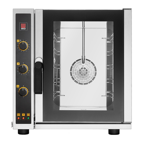
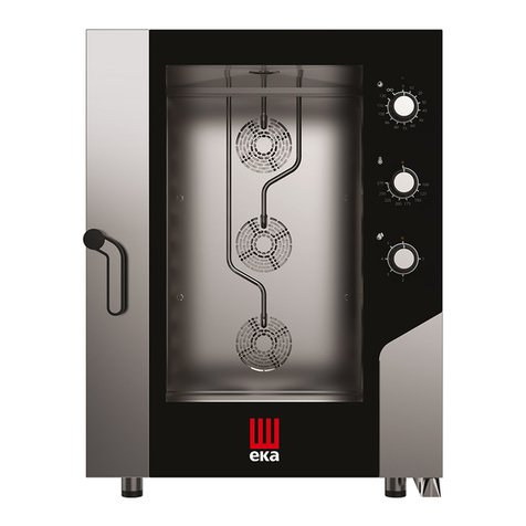
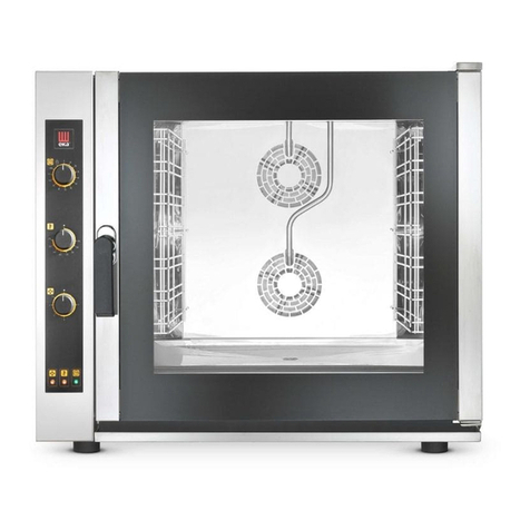
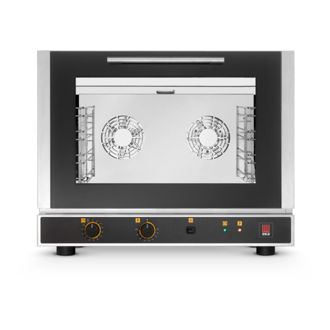
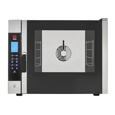
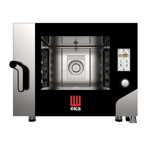
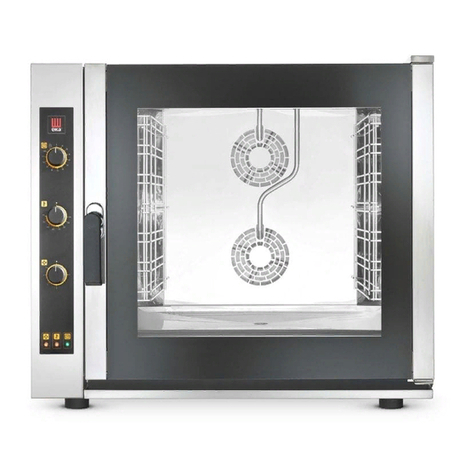
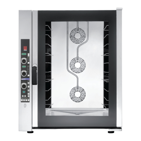
eka EKF 616 TC User manual

ORIGINAL OPERATING AND INSTRUCTION MANUAL
MODELS EKF 616 TC –EKF 664 TC –EKF 711 TC
EKF 1016 TC –EKF 1064 TC –EKF 1111 TC
EKF 1664 TC –EKF 2011 TC
EKF 1064 TC/0/029 –EKF 1111 TC/1/029
rev. 11
TECNOEKA S.r.l.
Via Marco Polo, n.11 - 35010 Borgoricco (Padova) Italy
Tel. +39.049.9300344 –+39.049.5791479 Fax +39.049.5794387
www.tecnoeka.com E-mail: info@tecnoeka.com

TECNOEKA Srl ___________________________________________________________ operating and instruction manual
page 2 _____________________________________________________________________________________________
EU DECLARATION OF CONFORMITY
Annex II A, of Directive 2006/42/EC
Manufacturer's name
TECNOEKA Srl
Manufacturer's address
Via Marco Polo, 11 - 35010 Borgoricco (PD)
Name of the person in
charge of the technical file
Lorenzo Minotto
Address of the person in
charge of the technical file
Via Marco Polo, 11 - 35010 Borgoricco (PD)
Product type
Electronic oven
Purpose of the product
Cooking food
Model
EKF 616 TC–EKF 664 TC–EKF 711 TC
EKF 1016 TC–EKF 1064 TC–EKF 1111 TC
EKF 1664 TC –EKF 2011 TC - EKF 1064 TC/0/029 –EKF
1111 TC/1/029
TECNOEKA Srl declares that the above mentioned products comply with all provisions
pertaining to the following directives:
Machine Directive 2006/42/EC;
Electromagnetic compatibility directive 2014/30/EU
TECNOEKA Srl declares that the above mentioned products comply with the following
harmonised directives:
EN 60335-1 ; EN 60335-2-42
EN 55014-1 ; EN 55014-2 ; EN 61000-3-2 ; EN 61000-3-3 ; EN 62233
TECNOEKA Srl declares that the above mentioned products also comply with the
following directives:
General product safety directive 2001/95/EC;
Directive restricting the use of hazardous substances in electrical and electronic equipment
2011/65/EU;
Directive on waste of electrical and electronic equipment 2012/19/EU.
TECNOEKA Srl declares that the above mentioned products comply with
(EC) Regulation 1907/2006
Borgoricco, 05/04/2017.
_________________________________
Board Representative Signature (Lora Cristina)

Electronic convection oven rev. 11 ________________MODD. EKF 616 TC –EKF 664 TC –EKF 711 TC –EKF 1016 TC
EKF 1064 TC –EKF 1111 TC –EKF 1664 TC –EKF 2011 TC
_________________________________________________________________________________________ page 3
Contents
1
Technical service
2
General information
3
Instructions for the installer
4
Instructions for the user
5
Settings menu
6
Accessories menu
7
Oven-user communication
8
Cleaning
9
Maintenance
10
Possible faults
11
Possible alarms
12
Electrical diagrams
13
Technical support
14
Information to users
15
Recipe book
16
The warranty
17
Availability and supply of spare parts
X:\Sgq\PRODOTTI\1 -FORNI\FORNO ELETTRICO\LEka\MANUALI D'USO - Forno Elettrico 40 60 90 - LEka\Lingua
Inglese\NUOVA GAMMA EF\Instruction manual TOUCH LINE - GB - rev. 10.doc

TECNOEKA Srl ___________________________________________________________ operating and instruction manual
page 4 _____________________________________________________________________________________________
1. Technical service
For periodic maintenance checks and repairs, contact your nearest Support Centre and only use
original spare parts. Failure to comply with this provision shall forfeit the warranty right.
2. General information
It is essential for this instruction manual to be stored together with the appliance for future
referencing; in the event of misplacing it, a copy must be obtained directly from the manufacturer.
This information has been prepared for your safety and that of others; therefore we kindly ask you
to read it carefully before installing and using the appliance.
If upon reception of the goods the packaging should not be intact or should it be damaged, affix
the following wording: “GOODS SUBJECT TO CHECK”, with the specification of the damage and
countersigned by the driver; file a written complaint with the seller within 4 calendar days (not
business days) from the date of delivery, after which no complaints shall be accepted.
The appliance is intended for professional use in institutional and professional kitchens and must
only be used by skilled personnel who have been trained on its proper use. For safety reasons the
appliance must be supervised during operation.
The appliance is not intended to be used by children and/or persons with impaired physical,
sensory or mental abilities, or who lack experience or knowledge, unless they are supervised by a
person responsible for their safety, or who has been instructed on using the appliance.
It is hazardous to modify or attempt to modify the features of this appliance.
The appliance must never be cleaned with direct water or steam jets, since any ingress of water
might affect its safety.
Before maintenance or cleaning disconnect the appliance from the power supply mains and let it
cool. In the event of failure or poor operation, switch off the appliance, close the water supply
cock, disconnect the power supply and contact an authorised Service Centre.
Any modification to the electrical system that might be required to be able to install the appliance
must be carried out by competent personnel only.
All installation and commissioning operations must be exclusively be performed by technically
skilled installers, according to the manufacturer's instructions and in compliance with national
standards in force.
For periodic maintenance checks and repairs, contact your nearest Support Centre and only use
original spare parts. Failure to comply with this provision shall forfeit the warranty right.
Note: The inappropriate or incorrect use and failure to comply with installation rules shall
invalidate any liability by the Manufacturers. In this connection, the instructions laid out under
“POSITIONING” (paragraph 3.6) must be strictly complied with.

Electronic convection oven rev. 11 ________________MODD. EKF 616 TC –EKF 664 TC –EKF 711 TC –EKF 1016 TC
EKF 1064 TC –EKF 1111 TC –EKF 1664 TC –EKF 2011 TC
_________________________________________________________________________________________ page 5
2.1 Technical data plate (example)
The “technical data” plate is located on the side of the appliance.
2.2 Technical features
Models
EKF 616 TC
EKF 664 TC
EKF 711 TC
EKF 1016 TC
EKF 1064 TC
EKF 1111 TC
EKF 1664 TC
EKF 2011 TC
EKF 1064 TC/0/029
EKF 1111 TC/1/029
Overall dimensions:
height
(with feet)
82.5cm
115cm
192cm
115cm
width
93.5cm
93.5cm
98.5cm
93.5cm
depth
93cm
93cm
103cm
93cm
Weight:
98kg
136.5kg
244.5kg
Maximum load per tray: GN1/1 –
600x400mm
4 –2kg
Total load trays: GN 1/1 –
600x400mm
28 –12kg
44 –20kg
80 –32kg
44 –20kg
Electrical power:
Convection
resistors
2
kW 10
3
kW 15
5
kW 30
3
kW 15
Maximum electrical power:
kW 10.5
kW 16
kW 30
kW 16
Electrical insulation class:
I
Casing protection degree:
IPX5
Water pressure:
kPa 100 –200
Power supply voltage:
400V 3N
50/60 Hz
230V 3
50/60 Hz
Power supply cable section:
5G 2.5 (5 x 2.5 mm2)
5G 10
(5 x 10 mm2)
4G 10
(4 x 10 mm2)
Power supply cable type:
H07RN-F
Power supply cable connection:
Type: Y
The noise level of the appliance in operation is less than 70 dB (A).
3. Instructions for the installer
The following instructions are aimed at the skilled installer for them to perform installation,
electrical and water connection operations in the most correct manner and according to the safety
regulations in force in the place of installation of the appliance.
The manufacturer shall not be liable for damage or harm to persons, pets or property arising from
installation errors. Nor are they responsible for any appliance breakage caused by faulty
installation.
CERTIFICATION
SERIAL NUMBER
EKF 1064 TC
5214010500
16 kW
IPX5
400V 3N50/60 Hz
400V 3N
50/60
Hz
kPa 100 - 200

TECNOEKA Srl ___________________________________________________________ operating and instruction manual
page 6 _____________________________________________________________________________________________
3.1 Storage
In the event the appliance has been warehoused at temperatures below 0°C (maximum allowed –
5°C), it must be brought back to a temperature of at least +10°C before operating it.
3.2 Transport of the appliance
During transport the appliance must be left in its packaging in order to protect it from any
external damage.
The weight of the appliance must also be taken into account in order to prevent overturning.
3.3 Unpacking the appliance
Remove packaging before installation. It consists of a wooden pallet supporting the appliance and
a cardboard casing protecting it. Ensure the appliance has not undergone any damage during
transport; otherwise immediately alert your dealer and/or carrier.
3.4 Removal of the protecting film
Before using the appliance accurately remove the special film protecting the stainless steel
components, avoiding to leave glue residues on the surfaces; if required, immediately remove
them using an appropriate solvent of non flammable type.
3.5 Disposal of packaging
The packaging must be disposed of in strict compliance with the regulations in force in the place
of installation of the appliance. The various materials (wood-paper-cardboard-nylon-metal staples)
the packaging consists of must be suitably separated and delivered to the suitable collection
centres. In any case adhere to environmental protection regulations.
3.6 Placement
Check the place of installation ensuring transit areas (any doors and corridors) are sufficiently wide
(the dimensions of the appliance without pallet are shown in Fig.1).
The appliance must be installed in a well-aerated room with permanent vents.
The maximum working height, referred to the highest surface level, must be 1.6 metres from the
floor. After installing the appliance apply the suitable adhesive symbol (supplied) at a height of 1.6
metres.
To assure accessibility and air circulation around the appliance, leave at least 50cm of space
between the left side and the wall (or other appliance), and at least 10 cm between the back and
the wall and between the right side and the wall (see Fig.1). It is strictly forbidden to obstruct,
even partially, the forced aeration vents on the left side, even for short periods of time.
Failure to comply with this explicit prohibition shall void any liability from the appliance's
manufacturer and immediately forfeit any warranty rights on the same, since its constructive
conformity has been deliberately impaired. For the same reason, do not place any appliances that
might produce heat sources and/or spray hot liquids (fryers) near the left side.
Should the appliance be installed near walls, shelves, tops and the like, these must be of the non
flammable or heat-insensitive type; otherwise, they must be protected by adequate fire retardant
coating. In this connection it is indispensable to act in compliance with the fire prevention
regulations in force. Cooking produces hot smoke and smells which are expelled from the suitable
vent device at the top of the appliance. It is recommended to place the appliance under an
extraction hood or to use the suitable TECNOEKA hoods, in order to convey the smoke to the
outside.

Electronic convection oven rev. 11 ________________MODD. EKF 616 TC –EKF 664 TC –EKF 711 TC –EKF 1016 TC
EKF 1064 TC –EKF 1111 TC –EKF 1664 TC –EKF 2011 TC
_________________________________________________________________________________________ page 7
3.6.1 Table top oven placement
The appliance must be placed in a perfectly horizontal position on a table or similar support; never
on the floor.
For safety reasons it is recommended to use the support produced by the manufacturer; otherwise
the weight of the appliance must be taken into account. The appliance is unsuitable for recessing.
Warning
In the event the appliance is positioned on a wheeled table/support, ensure the permissible
movement does not damage electrical wires, water pipes, drain pipes or anything else.
3.6.2 Placement of wheeled ovens
The appliance must be positioned on a flat and level floor. After placement, ensure the appliance
is horizontally aligned. This check may be carried out by placing a "bubble level" on the 4 top
sides of its casing. Ensure the tray trolley is able to go in and out of the cooking chamber easily,
without rubbing against the lower surface, even when it is "fully loaded". In the event this
operation should not be possible, the appliance feet must be adjusted to lower it so that the tray
trolley may be moved properly. In any case, upon completing adjustment, ensure the wheels of
the tray trolley, inserted in the cooking chamber, are raised from the floor (not more than 5 mm),
and that the trolley is supported by the suitable guides at the bottom of the appliance.
The tray trolley must be moved using the handgrip supplied. The handgrip must be inserted into
the suitable seats at the front of the trolley up to the "stopping point".
The tray trolley must be inserted inside the cooking chamber, freely sliding on the suitable guides
in the lower portion of the appliance.
Warning
Appliance malfunctioning may occur unless the tray trolley is correctly positioned.
3.7 Electrical connection
Connection to the power mains must be performed according to regulations in force. Before
performing the connection ensure that:
-the voltage and frequency of the power supply system match with
the specifications on the "technical data" plate affixed on the side of the appliance;
-the limiting valve and the system are able to withstand the appliance's load (see "technical data"
plate);
-the power supply system is fitted with effective earthing connection according to the regulations
in force;
-In the permanent connection to the mains, a protective pole switch must be provided between
the appliance and the mains with minimum opening between the contacts of overvoltage
category III (4000V), sized for the load and complying with applicable regulations (e.g. automatic
magnetic circuit breaker);
-the pole switch used for the connection is easily accessible with installed appliance;
-the yellow/green earthing cable is not interrupted by the switch;
-The appliance must be connected to an equipotential system the effectiveness of which must be
suitably assessed according to applicable regulations. This connection must be performed with
the suitable terminal located on the rear and marked with the symbol . The equipotential
conductor must have minimum section 2.5mm².
-when the appliance is operating, the power supply voltage does not deviate from the nominal
voltage value by ±10%;
-ensure the power supply cable does not enter in contact with the appliance's hot parts after
inserting it in the terminal board.
-if the power supply cable is damaged it must be replaced by the manufacturer or their technical
support service, or in any case by a person with similar qualifications, to prevent any risk.
TECNOEKA Srl ___________________________________________________________ operating and instruction manual
page 8 _____________________________________________________________________________________________
Installation and connection drawings
MODELS EKF 616 TC –EKF 664 TC –EKF 711 TC
Fig. 1 (Dimensions are expressed in mm )
Installation and connection drawings
1
USB PORT
3
SOCKET FOR CORE PROBE CONNECTION
4
WATER DRAIN PIPE (DN30)
5
WASHING WATER INLET
6
SOFTENED WATER INLET (THREADED SOLENOID VALVE¾”)
8
STEAM VENT
9
POWER SUPPLY CABLE RETAINER
10
WARNING HOT SURFACE
11
DO NOT OBSTRUCT AERATION VENTS
12
WATER INLET MAX.200kPa
13
SOFTENED WATER INLET MAX. 200kPa

Electronic convection oven rev. 11 ________________MODD. EKF 616 TC –EKF 664 TC –EKF 711 TC –EKF 1016 TC
EKF 1064 TC –EKF 1111 TC –EKF 1664 TC –EKF 2011 TC
_________________________________________________________________________________________ page 9
MODELS EKF 1016 TC –EKF 1064 TC –EKF 1111 TC
Fig. 1 (Dimensions are expressed in mm.)
1
USB PORT
3
SOCKET FOR CORE PROBE CONNECTION
4
WATER DRAIN PIPE (DN30)
5
WASHING WATER INLET
6
SOFTENED WATER INLET (THREADED SOLENOID VALVE¾”)
8
STEAM VENT
9
POWER SUPPLY CABLE RETAINER
10
WARNING HOT SURFACE
11
DO NOT OBSTRUCT AERATION VENTS
12
WATER INLET MAX.200kPa
13
SOFTENED WATER INLET MAX. 200kPa

TECNOEKA Srl ___________________________________________________________ operating and instruction manual
page 10 _____________________________________________________________________________________________
Installation and connection drawings
MODELS EKF 1664 TC –EKF 2011 TC
Fig. 1 (Dimensions are expressed in mm.)
1
USB PORT
3
SOCKET FOR CORE PROBE CONNECTION
4
WATER DRAIN PIPE (DN30)
5
WASHING WATER INLET
6
SOFTENED WATER INLET (THREADED SOLENOID VALVE¾”)
7
DRAIN PIPE COOLING WATER INLET
8
STEAM VENT
9
POWER SUPPLY CABLE RETAINER
10
WARNING HOT SURFACE
11
DO NOT OBSTRUCT AERATION VENTS
12
WATER INLET MAX.200kPa
13
SOFTENED WATER INLET MAX. 200kPa

Electronic convection oven rev. 11 ________________MODD. EKF 616 TC –EKF 664 TC –EKF 711 TC –EKF 1016 TC
EKF 1064 TC –EKF 1111 TC –EKF 1664 TC –EKF 2011 TC
_________________________________________________________________________________________ page 11
3.8 Power supply cable connection
(Modd. EKF 616 TC –EKF 664 TC –EKF 711 TC –EKF 1064 TC –EKF 1064 TC –EKF 1111 TC )
Remove the back and left side of the appliance to access the power supply terminal board.
Loosen the cable retainer at the rear (bottom) of the appliance (see Fig.1) and run the cable
through it until reaching the terminal board. Prepare conductors for connection with the terminal
board so that the earth conductor is the last to be extracted from its terminal in the event the
cable should be abnormally pulled.
Connect the 3 phase conductors (L1, L2, L3) of the cable to the terminals marked with
“1”(brown conductor) “2”(black conductor) and “3”(grey conductor) of the terminal board, the
neutral conductor (blue) to the terminal marked with “4” or “5” and the earth conductor
(yellow/green) to the terminal marked with the symbol (see diagram also available by the
terminal board):
(Mod. EKF 1064 TC/0/029 - EKF 1111 TC/1/029)
Remove the back and left side of the appliance to access the power supply terminal board.
Loosen the cable retainer at the rear (bottom) of the appliance (see Fig.1) and run the cable
through it until reaching the terminal board. Prepare conductors for connection with the terminal
board so that the earth conductor is the last to be extracted from its terminal in the event the
cable should be abnormally pulled.
Connect the 3 phase conductors (L1, L2, L3) of the cable to the terminals marked with “L1” “L2”
and “L3” of the terminal board, and the earth conductor (yellow/green) to the terminal marked
with the symbol (see diagram also available by the terminal board):
Tighten the cable retainer on the rear of the appliance; fit the left side and back on again. The
cable must be as per specifications in the "Technical features" table (paragraph 2.2). The
appliance must be connected to an equipotential system the effectiveness of which must be
suitably assessed according to applicable regulations.
This connection must be performed between different appliances through the suitable terminal
which is marked with the symbol . The equipotential conductor must have minimum section 2.5mm².The
equipotential terminal is at the rear of the appliance.

TECNOEKA Srl ___________________________________________________________ operating and instruction manual
page 12 _____________________________________________________________________________________________
3.8 Power supply cable connection (Models EKF 1664 TC –EKF 2011 TC)
Remove the lower back of the appliance to access the power supply terminal board. Loosen the
cable retainer located on the rear of the back (see Fig.1) and run the cable through it. The cable
must also go through the suitable hole on the electrical components panel, until reaching Prepare
conductors for connection with the terminal board so that the earth conductor is the last to be
extracted from its terminal in the event the cable should be abnormally pulled. The connection
must be done from the top of the terminal board.
Connect the 3 phase conductors to the input of the 3 terminals marked with “L1”(brown
conductor) “L2”(black conductor) e “L3”(grey conductor), the neutral conductor (blue) to the
input of the terminal marked with “N1”, (short circuit terminals “N1” , “N2” and “N3” among
them) and the earth conductor (yellow/green) to the terminal marked with the symbol (see
diagram also available by the terminal board):
Fit the lower back on again and tighten the cable retainer located on the rear. The cable must be
as per specifications in the "Technical features" table (paragraph 2.2). The appliance must be
connected to an equipotential system the effectiveness of which must be suitably assessed
according to applicable regulations. This connection must be performed between different
appliances through the suitable terminal which is marked with the symbol . The equipotential
conductor must have minimum section 2.5mm². The equipotential terminal is at the rear of the
appliance.
3.9 Connection to the water mains
The appliance must be supplied with softened drinking water, with hardness between 0.5°F and
5°F. and maximum temperature 30°C. It is obligatory to use a softener to reduce the formation
of limescale inside the cooking chamber. The water pressure must be between 100 and 200 kPa
(1.0 -2.0 bar). If the mains pressure exceeds 2.0 bar, install a pressure reducer upstream of the
appliance. If the value is lower than 1.0 bar use a pump to raise the pressure. The appliance is
equipped with flexible hose (1.5 metres) with threaded ¾” female fittings and relevant gaskets.
The old joints must not be used. Connection to the water mains must be performed through the
¾” threaded solenoid valve located at the rear (bottom) of the appliance (see Fig.1), interposing a
mechanical filter and a stopcock (before connecting the filter drain off a certain amount of water
to flush the pipe from any dirt).
Warning
Any damage caused by limescale or other chemicals contained in the water are not covered by
warranty.

Electronic convection oven rev. 11 ________________MODD. EKF 616 TC –EKF 664 TC –EKF 711 TC –EKF 1016 TC
EKF 1064 TC –EKF 1111 TC –EKF 1664 TC –EKF 2011 TC
_________________________________________________________________________________________ page 13
3.10 Water drain
A drain pipe comes out of the rear of the appliance (see Fig.1) to drain the cooking chamber.
This pipe must be connected to piping with 30 mm inner diameter (DN 30) resistant to steam
temperature (90°C-100°C).
To avoid choking the pipe should be stiff and there should be no "elbows" along the drain path.
The pipe must also maintain constant slope (min. 5%) along its entire length (the length
considered is that of the appliance's drain pipe at the drain point and must not exceed 2 metres).
The drain piping must be conveyed into an open floor drain (Fig.2); otherwise, there must be at
least 30 cm height difference between the drain pipe of the appliance and the drain point in order
to assure regular water drainage.
Furthermore, the minimum "air gap" must be 25 mm (distance between the drain pipe from the
appliance and the cup of the drain duct pipe).
In any case, for reasons of compliance with health regulations in force, the piping connected to
the drain pipe of the appliance must not be in direct contact with the drain point.
It is recommended to connect the appliance's drain to the grey water network through an
adequate syphon, in order to stop steam from coming out of the drain.
The connection to drain water must be done separately for each appliance; in case of several
appliances connected to the same drain pipe, ensure the pipe is suitably sized to assure regular
drainage with no hindrances.
FIG. 2 FIG. 3
3.11 Safety thermal devices
The appliance is equipped with a manually reset safety thermostat, to protect against excessive
and hazardous overheating which might accidentally occur inside it. In the event of tripping the
device interrupts power supply to the appliance.
3.12 Electronic circuit protection
The electronic circuit housed inside the electrical components compartment is protected by fuse.
3.13 Disposal of the appliance
The appliance is constructed with recyclable raw materials and does not contain toxic or
hazardous substances for persons and environment. Eventual disposal of the appliance and its
packaging must be carried out strictly following the regulations in force in the place of installation.
The different materials it is made up of must be separated by type of disposal and delivered to the
suitable collection centres. In any case adhere to environmental protection regulations.

TECNOEKA Srl ___________________________________________________________ operating and instruction manual
page 14 _____________________________________________________________________________________________
4. Instructions for the user
4.1 General information
-Use the appliance at room temperature between +5°C and +25°C. 35°C may be reached
occasionally.
-The temperature of the appliance's external surfaces may exceed 60°C, only touch control
elements. Burn hazard!
-When the appliance is first used it is recommended to operate it unladen for 40/50 minutes at
a temperature of 220/230°C. In this way all unpleasant and wholly normal smells due to
heating the thermal insulation enveloping the cooking chamber and the silicone used for its
external sealing are dissipated.
-Supervise the oven during operation.
-This appliance must only be used for the use it has been especially designed for, that is
cooking food in the oven; any other use is to be deemed improper.
-The appliance may be used for all types of baking of pastries, baked goods and food: fresh and
frozen; for reconditioning chilled and frozen food, for steam cooking of meats, fish and
vegetables.
-No foods containing easily flammable substances must be cooked, such as alcohol-based
foods; self-combustion phenomena might occur leading to fires and explosions in the cooking
chamber.
Pay attention to handling food containers during and after cooking: they might be very hot.
Wear appropriate protective thermal clothing to prevent burns
-In placing the food in the cooking chamber, maintain a space of at least 40 mm between trays
in order not to excessively obstruct air circulation.
-Do not use trays with sides higher than necessary: the sides form barriers that prevent hot air
circulation.
-Preheat the oven every time before cooking to achieve top performance.
-For cooking as consistently as possible, spread the food evenly in every tray taking into account
its size, layer or thickness.
-Avoid adding salt to food in the cooking chamber.
-To check correct progress of the cooking cycle use the chamber's internal lighting: avoid
uselessly opening the door, which causes wastes of energy and longer cooking times.
Warnings
To prevent boiling, do not use containers filled with liquids or food that liquefy with heat, in
excessive amounts that cannot be easily kept under control. For this reason, only use trays that let
you see inside the container.
When extracting a tray containing hot liquid pay attention not to spill any liquid: burn hazard!
4.1.1 Residual risks
After baking open the door with caution, to avoid the violent outflow of heat which might cause
burns. During oven operation pay attention to hot areas of its outer surfaces (marked on the
appliance). Do not use the door handle to move the appliance (possible glass breakage).
The supporting bench must be able to withstand the weight of the machine and house it
correctly. The appliance is fitted with electrical parts and must never be washed with a water or
steam jet. The appliance is electrically connected: disconnect the power supply before performing
any type of cleaning. To avoid incorrect connections of the appliance, the relevant electrical/water
connections are marked on the appliance by suitable identification plates.

Electronic convection oven rev. 11 ________________MODD. EKF 616 TC –EKF 664 TC –EKF 711 TC –EKF 1016 TC
EKF 1064 TC –EKF 1111 TC –EKF 1664 TC –EKF 2011 TC
_________________________________________________________________________________________ page 15
Only for mod. EKF 1664 TC e mod. EKF 2011 TC (wheeled models)
Appropriate heat protection clothing must be worn when acting on the release device to actuate
sliding (upwards) of the internal door glass (position to insert the tray trolley), burn hazard!
Appropriate heat protection clothing must be worn when acting on the internal door glass after a
cooking cycle to slide it downwards (washing position/cooking chamber pre-heating), burn
hazard!
Appropriate heat protection clothing must be worn when extracting the tray trolley from the oven
after a cooking cycle, burn hazard!
Ensure the tray trolley can be handled with ease, with no hindrance to insertion and extraction
operations: any collision may cause the spillage of hot liquids or food, burn hazard!
Close trays containing liquids so these cannot be spilled when they are hot, burn hazard!
When the tray trolley is inserted in the oven, before closing the door ensure the release device for
sliding the internal glass (door) has been activated and the glass is fully up: any impact of the
trolley against the glass might break it, injury hazard!
The trolley is fitted with a suitable rod for locking trays. The rod must always be inserted when the
trolley is handled during use: trays might fall, injury hazard!
If the tray trolley is not moved, the wheel parking brake must be engaged: the trolley might move
on uneven floors, injury hazard!
While loading and unloading the tray trolley, engage the wheel parking brake: the trolley might
move, injury hazard!
The tray trolley is mounted on wheels, therefore it might tip over if it is moved on uneven floors,
injury hazard!
When inserting or extracting the tray trolley into or from the oven, pay the utmost attention not
to accidentally damage the internal glass gasket of the door: it is recommended to open the oven
door completely while moving the trolley.

TECNOEKA Srl ___________________________________________________________ operating and instruction manual
page 16 _____________________________________________________________________________________________
4.2 Control panel
LCD DISPLAY
INCREASE PARAMETER VALUE
DECREASE PARAMETER VALUE
CONFIRM PARAMETER VALUE
STEP/PARAMETER SELECTION
AIR FLOW SPEED SETTING
"PRE-HEATING" SETTING
GENERAL SETTINGS MENU
PROGRAMMING
ACCESSORIES
RECIPE BOOK
START/STOP

Electronic convection oven rev. 11 ________________MODD. EKF 616 TC –EKF 664 TC –EKF 711 TC –EKF 1016 TC
EKF 1064 TC –EKF 1111 TC –EKF 1664 TC –EKF 2011 TC
_________________________________________________________________________________________ page 17
4.3 “Touch” control operation
The “TOUCH” control works by touching the screenprinted key (exclusively use your fingers and
no other utensils such as knives, forks, or other objects in general).
All oven functions are activated in this way. To make use of the control panel easier, only the keys
that may be activated are lit.
4.3.1 Switching on/off
Keep your finger on the “START/STOP” key for a few seconds and the display will show
the screen with the “EKA” logo, DATE/TIME. After 5’’ the screen dissolves and the oven
automatically readies for programming the cooking cycle: the “TIME” parameter screen is
displayed.
After 10 minutes if no key is activated, the “Touch” control goes into STAND-BY mode and only
the “START/STOP” key remains lit on the control panel.
To reactivate the “Touch” control, just touch the “START/STOP” key with your finger for
a few seconds. To activate the STAND-BY mode hold your finger on the “START/STOP”
key for a few seconds.
4.3.2 Manual operation
4.3.2.1 General information
The cooking cycle may be programmed by using the PARAMETER SCREEN (displays the value of
each individual parameter of the cooking cycle), or using the OVERVIEW SCREEN (simultaneously
displays all the cooking cycle parameter values). The PARAMETER SCREEN is displayed
automatically only when the cooking cycle is first set, after the oven is first switched on. In this
case the values of the parameters set must be confirmed by acting on the “SELECT” key.
In the OVERVIEW SCREEN the individually displayed parameter may also be selected. Choose the
parameter to be displayed with the “STEP” key, then touch the “SELECT” key and the
PARAMETER SCREEN is displayed.
The set value is automatically confirmed after 5’’ both in the OVERVIEW SCREEN and in the
PARAMETER SCREEN.
The RED SCREEN indicates WARNING when, while setting a step of the cooking cycle, the
parameter required to activate the step is missing (symbol in the direction of the number of
the step where the
operative parameter is missing) or the oven door is opened during the cooking cycle.
The RED SCREEN indicates ALARM (sound) when faults occur during oven operation that prevent
cooking cycle continuation or automatic washing cycle (the type of fault is described and
represented by a symbol).
For the various types of alarm see the relevant paragraph 11.

TECNOEKA Srl ___________________________________________________________ operating and instruction manual
page 18 _____________________________________________________________________________________________
Only for mod. EKF 1664 TC e mod. EKF 2011 TC (wheeled models)
These models are equipped with a special mobility system (patented) of the internal door glass.
The system allows you to “slide” the internal glass down or up, according to the application
needs.
Glass "down"
To obtain this position the oven door must be completely opened and by exerting adequate force,
“slide” the internal door glass down until the mechanical “lock” device is engaged: the closing
“click” can be heard (Fig. 4).
Fig. 4
Glass "up"
To obtain this position, the oven door must be opened (even partially) and by acting on the
suitable “lever” in the lower portion (right side) of the door, behind the external glass, activate the
“release” device to let the internal glass “slide” up automatically.
Important
If the internal glass “release” operation is performed before using the oven (cooking chamber still
cold), it is recommended to completely open the door and act on the suitable “lever” from the
inside of the door (fig. 5). If the internal glass “release” operation is performed after using the
oven (cooking chamber is hot), it is recommended to partially open the door, let the hot air vent
off, and act on the suitable “lever” from the outside of the door using adequate heat protection
clothing (fig. 6).
Fig. 5 Fig. 6
Glass “down” and door open with no tray trolley inserted
This position of the internal door glass lets the cooking chamber be hermetically closed without
the presence of the relevant tray trolley in or without needing to use a suitable closing partition.
The RED SCREEN (warning) is displayed with the words “DOOR GLASS LOWERED”.
When the door is closed, the OVERVIEW SCREEN is displayed (BLUE screen) and the oven may be
used for the “PRE-HEATING” function (paragraph 4.3.3.4) with no tray trolley in or for the SEMI-
AUTOMATIC CLEANING function (paragraph 8.2.2) and AUTOMATIC CLEANING of the cooking
chamber (with no tray trolley in) with the “KWT” system (paragraph 8.2.3).

Electronic convection oven rev. 11 ________________MODD. EKF 616 TC –EKF 664 TC –EKF 711 TC –EKF 1016 TC
EKF 1064 TC –EKF 1111 TC –EKF 1664 TC –EKF 2011 TC
_________________________________________________________________________________________ page 19
Glass “down” and door open with tray trolley in
With tray trolley in, the display shows the RED/BLUE SCREEN (flashing) with the words “LIFT
DOOR GLASS“. A sound alarm goes off, which is repeated intermittently. This internal glass
position with the tray trolley in, does not allow the door to be closed. If the trolley hits against the
glass it might break it:
injury hazard!
Glass “up” and door open with no tray trolley inserted
The RED SCREEN (warning) is displayed with the words “DOOR GLASS LIFTED”.
Glass “up” and door closed with no tray trolley inserted
The RED/BLUE SCREEN (flashing) is displayed with the words “LOWER DOOR GLASS”. A sound
alarm goes off, which is repeated intermittently. This internal glass position without the tray trolley
in, does not let the oven be used in any way
Glass “up” and door closed with tray trolley inserted
The PARAMETER SCREEN is displayed (cooking cycle parameters to be set) or the OVERVIEW
SCREEN (cooking cycle parameters already set); in both cases the oven may be regularly used for
baking.
Warnings
The ALARMS/WARNINGS screens are visible on the display as soon as a cooking cycle is set.
Adequate heat protection must be worn if the internal glass is moved after completing the “pre-
heating” stage or a cooking cycle, burn hazard!
4.3.2.2 Selection of cooking parameters
The following parameters may be set for each step of the cooking cycle (up to 9 steps):
1. Cooking time
2. Cooking chamber temperature
3. Core temperature
4. Delta T
5. Percentage (%) of humidity/steam activation
To confirm the set parameter and move to the next one, act on the “SELECT” key. The
airflow speed inside the cooking chamber may be modified (3 available speeds) by acting on
key .
Warning
A complete cooking cycle does not obligatorily require all 9 available steps, therefore it is possible
to set only the desired ones without affecting correct oven operation.
4.3.2.3 Cooking time or core temperature settings
Each cooking step is controlled by the cooking time parameter or core temperature parameter.
The time and core temperature parameters are mutually exclusive: if the core temperature
parameter is set, the time parameter is automatically deleted even if it has been previously set.
Warnings
Setting excessively short cooking times or excessively low core temperatures with respect to
correct values may lead to incomplete cooking.
Setting excessively long cooking times or excessively high core temperatures with respect to
correct values may result in excessively dry food, with the risk of burning the surface.

TECNOEKA Srl ___________________________________________________________ operating and instruction manual
page 20 _____________________________________________________________________________________________
4.3.3 Parameter setting
4.3.3.1 Cooking TIME setting (Parameter screen)
With the “STEP” key the following may be set:
1. TIME
2. PAUSE
3. MAINTENANCE
1. TIME
The parameter is settable from a minimum of 0h 01’ to 9h 59’ maximum. In the event of
MANUAL mode cooking cycle, in STEP 1 it is possible to also set an “INF” time (INFINITE):
The oven continues working until it is switched off by the operator.
2. PAUSE
This option may be set for a time between 0h 01’ and 23h 59’.
If the PAUSE is entered in STEP 1, it allows “DELAYED START” of the cooking cycle, which
is useful for foodstuff that needs to raise before cooking.
If the PAUSE is entered after STEP 1, it allows “thermal pressure” on the product to be
limited.
3. MAINTENANCE
This option makes it possible to maintain a constant temperature of 75°C within the
cooking chamber until the oven is switched off by the operator.
The PARAMETER SCREEN reads: “OFF”
use the key to enable this option (the display then reads ”ON”) which is
confirmed with the “SELECT” key;
use the key to disable this option (the display reads “OFF” again) which is confirmed
with the “SELECT” key.
When this option is active, at the end of the cooking cycle the display reads: “OVEN IN
MAINTENANCE”.
When the cooking cycle is active the display reads: “COOKING IN PROGRESS”
When the cooking cycle is in “PAUSE” the display reads: “BAKING STARTS IN” (count-down)
With “BAKING IN PROGRESS”
: the display shows the count-down of the set time in the direction
of the symbol and on the right the total time set of the cooking cycle (of 1 or more STEPS).
Important
The value of the set parameter may be confirmed immediately in the PARAMETER SCREEN
with the “SELECT” key; otherwise, the value is confirmed automatically after 5”.
4.3.3.2 TEMPERATURE setting (Parameter screen)
With the “STEP” key the following may be set:
1. TEMPERATURE IN COOKING CHAMBER
2. CORE TEMPERATURE (
The core probe is not standard supplied but is an optional accessory)
This manual suits for next models
9
Table of contents
Other eka Oven manuals

eka
eka EKF 464 TC User manual

eka
eka EKF 711 EV User manual

eka
eka EKF 416 AL P User manual

eka
eka EKF 1111 E UD User manual

eka
eka ekf 711 p User manual

eka
eka EKF 611 CTC User manual

eka
eka MKF 464 S User manual

eka
eka MILLENNIAL MKF 464 TS User manual

eka
eka KF 610 User manual

eka
eka KF 630 D UD User manual

eka
eka KF 1001G User manual

eka
eka KF 725 UD User manual

eka
eka EKF 523 UD User manual

eka
eka EKF 711G UD User manual

eka
eka EKF 711UD-EKF 664UD-EKF 664 UD-HTEKF 664... User manual

eka
eka KF 912 IX User manual

eka
eka MKF 464 BM Manual

eka
eka EKF 523 NT User manual

eka
eka KF 1010 EV UD User manual

eka
eka EKF 412 NALU User manual