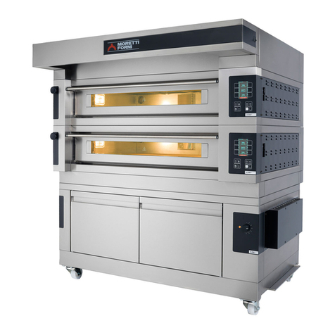
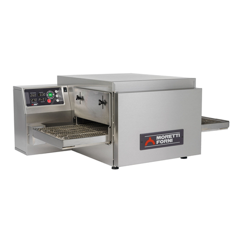
Moretti Forni T Series User manual

T64
E
T75E
T97E
TT98
E
Forno elettrico
Electric oven
Four electrique
Elektrische Ofen
Horno Electrico
ن
Manuale di
istruzioni
Instructions manual
Manuel d’instructions
Bedienungsanleitung
Manual instrucciones
ما د
Numeri di matricola / Serial numbers :
Cod.7334 70
Ver.: A

Via A.Meucci, 4 - 61037 - Mondolfo (PU) ITALIA
Tel. +39-0721-96161 - Fax +39-0721-9616299
H t t p : / / w w w . m o r e t t i f o r n i . c o m
e - m a i l : i n f o @m o r e t t i f o r n i . c o m
DICHIARAZIONE CE DI CONFORMITA’
DECLARATION OF CONFORMITY CE
Il costruttore /The manufacturer MORETTI FORNI S.P.A.
Indirizzo del costruttore/ Manufacturer address:
Via A. MEUCCI N. 4
61037 MONDOLFO ( PU)
DICHIARA CHE /
DECLARES THAT
I FORNI ELETTRICI / THE ELETRIC OVENS
PM 60.60-72.72-65.105-105.65-105.105 F45E M90L - M130L F-S KX
PD 60.60-72.72-65.105-105.65-105.105 F50E-F55E-F100E-F105E F30L UM
iD 60.60-72.72-65.105-105.65-105.105/M R14E F60-80L UM MODULO HI-TECH AC
iD 60.60-72.72-65.105-105.65105.105/D T64E - T75E – T97E – TT98E F45-50-100L UM RIALTO HI-TECH BCD
P60E-P80E F55-105L UM AMALFI HI-TECH ABC
P120E A-B-C L72.72-65.105-105.105-105.65 S100L UM – S120L UM – S125L UM BAKY 5TE
AMALFI A-B-C-D L60.60 - LU60.60 AHL-MHL-RHL
S100E – S120E – S125E AMALFI L-P60L-P80L-P120L KX60.60-72.72-65.105-105.65-105.105 AHL UM-MHL UM-RLH UM
M90E A-C P60L UM-P80L UM-P120L UM P60KX-P80KX-P120KX F60-80L
M130E A-B-C P110L – P150L AMALFI KX AHKX MHKX RHKX
F30E-F60E-F80E S100L – S120L – S125L M90KX - M130KX iB 5TE
sono conformi alle seguenti direttive /
are in accordance with the directives :
a) Direttiva Bassa Tensione 2014/35/UE e successive modifiche
Low-tension directive 2014/35/EU and next modifications
b) Direttiva Compatibilità Elettromagnetica 2014/30/UE e successive modifiche
Electromagnetic compatibility directive 2014/30/EU and next modifications
Mondolfo 20th April 2016

IT/
11
5 MANUTENZIONE STRAORDINARIA
5.1 OPERAZIONI PRELIMINARI DI SICUREZZA
ATTENZIONE! Prima di effettuare qualsiasi operazione di
manutenzione fermare l’apparecchiatura come da procedura al punto 3.3 ed
interrompere l'alimentazione elettrica scollegando il cavo d’alimentazione dalla
presa di corrente.
Le operazioni devono essere eseguite dopo che è avvenuto il raffreddamento
dell’apparecchiatura.
Illuminare la zona di lavoro durante le fasi di manutenzione e d’utilizzo
notturno o in caso di scarsa visibilità.
Tutte le operazioni di manutenzione e di riparazione devono essere eseguite con
idonee attrezzature antinfortunistiche da personale tecnico specializzato
munito di regolare licenza, riconosciuto ed abilitato dalla ditta costruttrice.
L’apertura dello sportello del forno protetto da lucchetto (fig.10 part.H) può
essere effettuata solo da tecnici specializzati informati sui potenziali rischi ed
equipaggiati delle opportune protezioni.
Tutti gli accorgimenti sono determinati per la buona conservazione
dell’apparecchiatura e la loro mancata osservanza potrebbe causare seri danni
che esulano dalla garanzia ed esposizione a rischi.
ATTENZIONE! Periodicamente (almeno una volta all’anno), ed
ogni qualvolta si presentino anomalie di funzionamento, l’apparecchiatura deve
essere controllata da un tecnico specializzato che deve verificare lo stato
dell’apparecchiatura; in questa occasione verificare la funzionalità del
termostato di sicurezza ed ispezionato l’interno del quadro elettrico ed il
ventilatore di raffreddamento (ove previsto) e pulirli dall’eventuale polvere
presente.
Accedere anche a tutti i vani laterali e posteriore ed aspirare accuratamente
eventuale polvere o farina depositata all’interno.
ATTENZIONE! Solo per T64E: se l’apparecchiatura viene
sganciata dagli ancoraggi che la fissano a terra, prestare la massima attenzione
alla stabilità della stessa in particolare durante la movimentazione, non lasciare
l’apparecchiatura incostudita e ripristinare gli ancoraggi appena possibile.
5.2 PULIZIA GENERALE
ATTENZIONE! Sfilando i componenti all’interno della camera di
cottura, si corre il rischio di incappare in bordi taglienti (alette degli elementi
riscaldanti, ecc…) per cui tutte le operazioni devono essere eseguite con
opportuni dispositivi di protezione
(guanti, occhiali, ecc…) da personale informato di tali rischi prestando la
massima attenzione.
Eseguite le operazioni al punto 5.1 per la pulizia procedere come segue.
Provvedere regolarmente alla pulizia generale dell’apparecchiatura. Dopo il
raffreddamento dell’apparecchio rimuovere accuratamente da tutti i componenti sia
interni che esterni tutti i residui che si sono creati utilizzando un panno o spugna
inumiditi, eventualmente con acqua saponata e poi sciacquare ed asciugare, pulendo
le parti satinate nel verso della satinatura.
NOTA: Le soffianti interne al termine della pulizia devono essere
rimontate nelle posizioni originali. Se i condotti dell’aria vengono montati in
modo errato le proprietà di cottura saranno alterate.
NOTA: solo TT98E: Nel rimontaggio delle soffianti rispettare la
pallinatura dei componenti come riportato in etichetta (fig 16 part. M).
ATTENZIONE! Regolarmente asportare accuratamente dalla
camera di cottura gli eventuali grassi fuoriusciti in fase di cottura in quanto
causa di possibili deflagrazioni.
NOTA: E’ opportuno pulire regolarmente l’estremità accessibile delle
termocoppie al fine di mantenerne l’efficacia nel tempo.
ATTENZIONE! Non lavare l’apparecchiatura con getti d’acqua
diretti o in pressione. Evitare che l'acqua o eventuali prodotti utilizzati,
vengano a contatto con le parti elettriche.
E’ vietato utilizzare per la pulizia detergenti nocivi alla salute.
NOTA: Non pulire i cristalli temperati degli sportelli quando sono
ancora caldi.
Non utilizzare solventi, prodotti detergenti contenenti sostanze aggressive
(clorate, acide, corrosive, abrasive, ecc…) o utensili che possano
danneggiare le superfici; prima di riavviare prestare attenzione a non
lasciare nell’ apparecchiatura quanto usato per la pulizia.
5.2.1 SMONTAGGIO COMPONENTI
ATTENZIONE! Alcune operazioni di seguito elencate, come la
rimozione del nastro, necessitano di almeno due persone.
Eseguite le operazioni al punto 5.1 per accedere a tutte le parti procedere come
segue:
- Togliere il lucchetto (fig.10 part.H), aprire l’agganciatore (fig.10 part.R) ed
aprire la porta anteriore (fig.10 part.S).
- Sfilare le soffianti superiori (solo TT98E: sfilare prima quelle centrali).
- Alzare le due paratie laterali regolabili (fig.10 part.I) tramite i pomelli (fig.10
part.L).
- Sfilare l’eventuale optional supporto stazionamento prodotto (fig.9).
- Sfilare i raccogli farina destro e sinistro (fig.9 part.T).
- Sfilare la copertura giunto nastro(fig.16 part.U) svitando la vite che la blocca
(fig.16 part.X).
- Sollevare il nastro trasportatore dal lato motore di alcuni centimetri e sfilare il
giunto nastro (fig.16 part.Z).
- Sfilare il nastro trasportatore dal lato motore (fig.16).
- Sfilare le soffianti inferiori (solo TT98E: sfilare prima quelle centrali).
- Eseguire le operazioni necessarie.
5.2.2 MONTAGGIO COMPONENTI
ATTENZIONE! Alcune operazioni di seguito elencate, come il
montaggio del nastro, necessitano di almeno due persone.
NOTA: solo per TT98E: Nel rimontaggio delle soffianti rispettare la
pallinatura dei componenti come riportato in etichetta (fig 16 part. M) e
rimontare prima le soffianti laterali e poi le centrali.
NOTA: solo per T64E e TT98E: rimontando le soffianti prestare la
massima attenzione che i tubicini portatermocoppie entrino bene all’interno
della soffiante; accertarsi sempre che le soffianti arrivino bene in fondo sulla
parete verticale del forno.
Nel caso si fossero create delle asperità che non fanno scorrere bene il
pannello bugnato sul corpo soffiante toglierle con carta abrasiva finissima
(grana 600)
Eseguite le operazioni al punto 5.1 per montare i componenti procedere come
segue:
- Infilare le soffianti inferiori.
- Infilare il nastro trasportatore dal lato motore (fig.16) e posizionarlo nel suo
alloggiamento controllando che l’albero del nastro trasportatore e la
motorizzazione siano allineati.
- Verificare che i due giunti metallici siano a squadro tra loro, eventualmente
ruotare l’albero del nastro fino a portarlo a squadro per permettere l’inserimento
del giunto centrale (fig.16 part.Z), sollevare il nastro trasportatore dal lato motore
di alcuni centimetri ed infilare il giunto centrale nastro.
- Controllare che la trasmissione sia allineata, infilare la copertura giunto nastro
(fig.16 part.U) ed invitare la vite di bloccaggio (fig.16 part.X).
- Infilare i raccogli farina destro e sinistro (fig.9 part.T).
- Infilare l’eventuale optional supporto stazionamento prodotto (fig.9).
- Riposizionare all’altezza desiderata le paratie laterali regolabili.
- Infilare le soffianti superiori.
- Chiudere la porta anteriore (fig.10 part.S), se la porta non si chiude vuol dire
che le soffianti non sono arrivate in posizione, non forzare la porta, fare scorrere
le soffianti fino in fondo e richiudere la porta; chiudere l’agganciatore (fig.10
part.R) inserire e chiudere il lucchetto (fig.10 part.H).
ATTENZIONE!Ricordarsi di togliere la chiave dal lucchetto.
ATTENZIONE
LE ISTRUZIONI SEGUENTI RELATIVE ALLA “MANUTENZIONE
STRAORDINARIA” SONO STRETTAMENTE RISERVATE A PERSONALE
TECNICO SPECIALIZZATO MUNITO DI REGOLARE LICENZA, RICONOSCIUTO
ED ABILITATO DALLA DITTA COSTRUTTRICE.

IT/
12
5.3 ACCESSO AI COMPONENTI ELETTRICI
5.3.1 APERTURA PANNELLO PORTA COMPONENTI ELETTRICI
Eseguite le operazioni al punto 5.1 per l’apertura del pannello porta componenti
elettrici procedere come segue:
- Togliere le viti (fig.17 part.V).
T75E-T97E: Allentare il bocchettone pressacavo (fig.11 part.M).
- Fare scorrere verso l’esterno il pannello porta componenti elettrici (fig.17 part.Z),
facendo scorrere all’interno del bocchettone il cavo di alimentazione (fig.11 part.N).
- Infilare le due viti (fig.17 part.Y) negli appositi fori e fermare usando i due dadi
(fig.17 part.K) posizionati sulla vite (fig.17 part.J).
TT98E: Per i componenti posizionati sul lato opposto motoriduttore aprire
ruotandolo il pannello porta interuttori (fig.17 part.Z); mentre per accedere ai
componenti lato motoriduttore svitare le 2 viti di fissaggio (fig.16 part L) e ruotare il
pannello laterale.
T64E: Per accedere ai componenti elettrici svitare le 2 viti laterali di fissaggio e
ruotare il pannello laterale per accedere al vano componenti elettrici.
5.3.2 SOSTITUZIONE COMPONENTI QUADRO ELETTRICO
Eseguite le operazioni al punto 5.1, per la sostituzione di componenti del quadro
elettrico procedere come segue:
- Aprire il pannello porta componenti elettrici seguendo la procedura al punto 5.3.1
- Scollegare elettricamente il componente.
- Sostituire il componente.
- Eseguire le operazioni inverse per il rimontaggio, prestando attenzione di collegare
correttamente il componente.
- Chiudere il pannello porta componenti elettrici seguendo la procedura al punto
5.3.3.
NOTA:Se viene sostituita la scheda elettronica eseguire un Reset generale
dell’apparecchiatura come da punto 5.17.
5.3.3 CHIUSURA PANNELLO PORTA COMPONENTI ELETTRICI
Eseguite le operazioni al punto 5.1 per la chiusura del pannello porta componenti
elettrici procedere come segue:
T75E-T97E: Togliere i due dadi (fig.17 part.K)e riposizionarli sulla vite (fig.17
part.J).
- Fare scorrere verso l’interno il pannello porta componenti elettrici (fig.17 part.Z)
facendo scorrere all’esterno del bocchettone il cavo di alimentazione (fig.11 part.N).
- Montare le viti (fig.17 part.V).
- Serrare il bocchettone pressacavo (fig.11 part.M).
TT98E: Per il quadro componenti posizionato sul lato opposto motoriduttore
chiudere ruotandolo il pannello porta interuttori (fig.17 part.Z) e montare le viti
(fig.17 part.V). Per il quadro porta componenti lato motoriduttore ruotare il pannello
laterale ed avvitare le 2 viti di fissaggio (fig.16 part L).
T64E: Chiudere il pannello laterale ruotandolo ed avvitare le 2 viti di fissaggio
laterali.
ATTENZIONE! Facendo scorrere e riposizionando in posizione di
chiusura il pannello portacomponenti elettrici prestare la
massima attenzione a non sbucciare, incastrare o schiacciare i fili o il capillare
del termostato di sicurezza.
5.3.4 SOSTITUZIONE FUSIBILE
Sul circuito elettrico è presente un fusibile che nel caso si bruci non permette l’avvio
dell’apparecchiatura e del pannello comandi, in tal caso verificare lo stato del
fusibile ed eventualmente sostituirlo.
Eseguite le operazioni al punto 5.1, per intervenire procedere come segue:
- Aprire il pannello porta componenti elettrici seguendo la procedura al punto 5.3.1
- Sfilare il fusibile (fig. 17 part. N), controllarlo ed eventualmente sostituirlo con uno
di pari caratteristiche.
- Eseguire le operazioni inverse per il rimontaggio.
- Chiudere il pannello porta componenti elettrici seguendo la procedura al punto
5.3.3.
5.3.5 SOSTITUZIONE SPAZZOLE MOTORE NASTRO
(solo per T75E-T97E-TT98E)
NOTA: Il motore del nastro (Tav.A e B part.42) ha all’interno delle
spazzole (Tav.A e B part.35) che lavorando si consumano. Controllare
regolarmente che le spazzole non siano usurate altrimenti sostituirle
(all’interno del quadro portamotoriduttore viene data in dotazione una coppia
di spazzole di ricambio); è buona norma avere a disposizione delle spazzole di
ricambio.
Eseguite le operazioni al punto 5.1, procedere come segue:
- Aprire il pannello porta componenti lato motoriduttore seguendo la procedura al
punto 5.3.1
- Svitare i cappucci di copertura delle spazzole ed estrarre le spazzole
- Inserire le spazzole nuove e riinvitare i cappucci di copertura.
- Chiudere il pannello porta componenti elettrici seguendo la procedura al punto
5.3.3.
5.3.6 SOSTITUZIONE MOTORE/MOTORIDUTTORE NASTRO
Solo per T75E-T97E-TT98E: dopo la sostituzione di alcuni treni di spazzole
può essere necessario sostituire il motore del nastro (Tav.A e B part.42).
Eseguite le operazioni al punto 5.1, procedere come segue:
Aprire il pannello porta componenti lato motoriduttore seguendo la procedura al
punto 5.3.1
- Smontare il motoriduttore, portarlo su un piano di lavoro e sostituire il motore
(ove previsto).
- Rimontare il motoriduttore al forno prestando attenzione di riallinearlo
correttamente all’albero del nastro.
Chiudere il pannello porta componenti elettrici seguendo la procedura al punto
5.3.3.
5.4 SOSTITUZIONE DEL TERMOSTATO DI SICUREZZA
ATTENZIONE! Verificare periodicamente la funzionalità del
termostato di sicurezza.
Eseguite le operazioni al punto 5.1, per la sostituzione del termostato di sicurezza
procedere come segue:
T75E T97E: Togliere la paratia laterale regolabile sinistra (fig.10 part.I)
svitando i pomelli (fig.10 part.L).
- Togliere il portello sinistro superiore (fig.18 part.A) svitando le viti di
fissaggio.
- Scostare la coibentazione ed allentare le due viti (fig.19 part.C) che bloccano il
sensore termostato.
- Togliere il pannello posteriore (fig.19 part.D) svitando le viti di fissaggio e
sfilare il sensore del termostato posto all'interno della coibentazione.
- Aprire il pannello porta componenti elettrici seguendo la procedura al punto
5.3.1.
- Togliere il tappo copri pulsante di riarmo e svitare il dado di fissaggio del
termostato (fig.14 part.P).
- Scollegare i faston del termostato.
- Sostituire il termostato con il relativo sensore e ripristinare la parte di
coibentazione eventualmente danneggiata.
- Eseguire le operazioni inverse per il rimontaggio.
- Chiudere il pannello porta componenti elettrici seguendo la procedura al punto
5.3.3.
TT98E: il forno è dotato di due termostati di sicurezza indipendenti a riarmo
manuale, uno per il lato sinistro (fig.14 part.P) ed uno per il lato destro del forno
(fig.36 part.G).
Aprire la porta anteriore (fig.10 part.S) e sfilare il nastro trasportatore dalla
camera di cottura eseguendo le operazioni indicate nel punto 5.2.1.
- Sfilare la soffiante inferiore sinistra al fine di verificare il posizionamento
dell’attuale sensore del termostato attraverso la camera di cottura.
- Togliere il portello inferiore (fig.36 part.A o H) svitando le viti di fissaggio.
- Sfilare il sensore del termostato di sicurezza.
- Aprire il pannello porta componenti dal lato interessato seguendo la procedura
al punto 5.3.1.
- Rimuovere il portello di chiusura collocato all’interno del carter protezione
componenti (fig. 36 part.C o L) svitando le 2 viti di fissaggio
- Svitare il dado di fissaggio del termostato.
- Scollegare i faston del termostato.
- Sostituire il termostato e posizionare correttamente il sensore come verificato in
precedenza attraverso la camera di cottura.
- Eseguire le operazioni inverse per il rimontaggio.
- Chiudere il pannello porta componenti seguendo la procedura al punto 5.3.3.
T64E: Aprire la porta anteriore (fig.10 part.S) e sfilare il nastro trasportatore
dalla camera di cottura eseguendo le operazioni indicate nel punto 5.2.1.
- Sfilare la soffiante inferiore dal lato interessato al fine di verificare il
posizionamento dell’attuale sensore del termostato attraverso la camera di
cottura.
- Aprire il pannello porta componenti seguendo la procedura al punto 5.3.1.
- Scollegare i faston del termostato.
- Togliere il tappo copri pulsante di riarmo e svitare il dado di fissaggio del
termostato (fig.14 part.P).
- Sfilare il sensore del termostato di sicurezza.
- Sostituire il termostato e posizionare correttamente il sensore come verificato in
precedenza attraverso la camera di cottura.
- Eseguire le operazioni inverse per il rimontaggio.
- Chiudere il pannello porta componenti seguendo la procedura al punto 5.3.3.
5.5 SOSTITUZIONE DELLE TERMOCOPPIE
Eseguite le operazioni al punto 5.1, per la sostituzione delle termocoppia
procedere come segue:
- Per la termocoppia superiore togliere la paratia laterale regolabile sinistra (o
destra nel TT98E) (fig.10 part.I) svitando i pomelli (fig.10 part.L).
- Per la termocoppia inferiore togliere il nastro trasportatore seguendo la
procedura al punto 5.2.1.

IT/
13
T75E T97E: il forno è dotato di due termocoppie, una Superiore ed una Inferiore.
Togliere il portello sinistro superiore o inferiore (fig.18 part.A-W) svitando le viti di
fissaggio, per accedere alla termocoppia superiore o inferiore.
- Svitare il dado di fissaggio della termocoppia (fig.19 part.E).
- Scollegare i due cavi di alimentazione della termocoppia.
- Sostituire la termocoppia.
- Eseguire le operazioni inverse per il rimontaggio, prestando attenzione di collegare
i connettori secondo le giuste polarità.
- Per rimontare il nastro trasportatore seguire la procedura al punto 5.2.2.
T64E-TT98E: il T64E è dotato di due termocoppie (Superiore, Inferiore), il TT98E
di quattro termocoppie (Superiore, Inferiore Sinistra, Destra).
NOTA: Per qualsiasi motivo si debba rimuovere o spostare una
termocoppia, al fine della sua integrità, È TASSATIVO MOVIMENTARLA
PRENDENDOLA ESCLUSIVAMENTE SUL TUBETTO METALLICO E
MAI SUL CAVO.
-Aprire pannello porta componenti seguendo la procedura al punto 5.3.1
- Togliere il portello corrispondente (solo TT98E) (fig.36 part.A-B-H-I)
- Togliere la soffiante corrispondente seguendo la procedura al punto 5.2.1.
- Svitare la vite di fissaggio della termocoppia con chiave a brugola (fig.37 part.V).
- Per sfilare i cavi delle termocoppie sul lato destro (solo TT98E) è necessario
smontare i pannelli posteriore (fig.38 part. T-S)
- Scollegare il cavo dalla scheda elettronica e sfilare la termocoppia.
- Sostituire la termocoppia prestando attenzione di collegare i connettori secondo
le giuste polarità.
NOTA: Assicurarsi che l’estremità di ogni termocoppia sia sempre
posizionata sul taglio inclinato del tubo come riportato in fig 37 part W
- Rimontare la soffiante corrispondente seguendo la procedura al punto 5.2.2.
- Eseguire le operazioni inverse per il rimontaggio.
- Chiudere pannello porta componenti seguendo la procedura al punto 5.3.3.
- Per rimontare il nastro trasportatore seguire la procedura al punto 5.2.2.
5.6 SOSTITUZIONE DELLE RESISTENZE
Eseguite le operazioni al punto 5.1, per la sostituzione delle resistenze procedere
come segue:
T75E-T97E-TT98E
- Per le resistenze superiori togliere le paratie laterali regolabili destra e sinistra
(fig.10 part.I) svitando i pomelli (fig.10 part.L).
- Per le resistenze inferiori togliere il nastro trasportatore seguendo la procedura al
punto 5.2.1.
T75E T97E: Togliere i portelli superiori o inferiori (fig.18 part.A-B-W-Z) svitando
le viti di fissaggio, per accedere alle relative resistenze.
- Scollegare da entrambi i lati i fili d’alimentazione delle resistenze;
- Togliere da entrambi i lati la coibentazione cercando di non rovinarla.
- Dal lato sinistro con una chiave a tubo togliere il dado (fig.19 part.F) sulla
resistenza che si desidera cambiare.
- Dal lato destro con un cacciavite togliere le viti (fig.20 part.G),sfilare la piastra
porta resistenza e da questo lato sfilare la resistenza.
- Eseguire le operazioni inverse per il rimontaggio delle nuove, ripristinare la parte
di coibentazione eventualmente danneggiata prestando attenzione che non arrivi ai
contatti elettrici.
TT98E:
Resistenze inferiori o superiori sinistre TT98E
-Aprire il pannello porta interruttori seguendo la procedura al punto 5.3.1
- Togliere il carter protezione componenti elettrici (fig.36 part N)
- Togliere i portelli superiori o inferiori (fig.36 part.H-I-L-M)
- Scollegare i cavi elettrici
- Rimuovere i carter protezione coibentazione resistenze (fig.37 part.Q-R)
- Spostare la coibentazione cercando di non rovinarla.
- Svitare le viti di fissaggio piastrino resistenze.
- Sostituire la resistenza danneggiata
- Eseguire le operazioni inverse per il rimontaggio.
- Chiudere il pannello porta componenti elettrici seguendo la procedura al punto
5.3.3.
Resistenze inferiori o superiori destre TT98E
- Aprire il pannello laterale svitando le 2 viti di fissaggio (fig.16 part L)
- Sfilare la copertura giunto nastro(fig.16 part.U) svitando la vite che la blocca
(fig.16 part.X).
- Sollevare il nastro trasportatore dal lato motore di alcuni centimetri e sfilare il
giunto nastro (fig.16 part.Z).
- Rimuovere il carter inferiore sul giunto nastro (fig.36 part F)
- Togliere il carter protezione motore nastro (fig.36 part E)
- Togliere i portelli superiori o inferiori (fig.36 part.A-B-C-D)
- Scollegare i cavi elettrici
- Rimuovere i carter protezione coibentazione resistenze (fig.37 part.O-P)
- Spostare la coibentazione cercando di non rovinarla.
- Svitare le viti di fissaggio piastrino resistenze.
- Sostituire la resistenza danneggiata.
- Eseguire le operazioni inverse per il rimontaggio.
– Richiudere il pannello laterale ed avvitare le 2 viti di fissaggio (fig.16 part L)
NOTA: Assicurarsi che all’interno del forno TT98E la parte finale
delle resistenze sostituite entrino nella loro sede, vedere la corrispondente
posizione dall’interno della camera di cottura smontando i componenti
come da procedura al punto 5.2.1, per il rimontaggio seguire la procedura al
punto 5.2.2.
T64E
-Togliere il pannello posteriore svitando le viti di fissaggio.
-Scollegare il motore ed i faston del sensore termico
-Individuare il gruppo di resistenze da sostituire tenendo presente che i
terminali lato quadro elettrico sono relativi alle resistenze del cielo, quelli
opposti sono relativi alle resistenze della platea.
-Scollegare i terminali delle resistenze utilizzando una seconda chiave sul
controdado come antirotazione per evitare la forzatura del terminale.
NOTA: Eventuali forzature dei terminali delle resistenze in fase di
collegamento/scollegamento dei cavi elettrici compromettono
irrimediabilmente tutto il gruppo di resistenze!
-Togliere i pannelli di contenimento lana
- Rimuovere il pannello posteriore camera di cottura svitando le viti di fissaggio.
- Portarsi su di un piano di lavoro.
- Sostituire la resistenza danneggiata.
- Eseguire le operazioni inverse per il rimontaggio.
5.7 SOSTITUZIONE DEL DISPLAY TFT
Eseguite le operazioni al punto 5.1, per la sostituzione del Display TFT o quadro
comandi procedere come segue:
- Smontare la staffa (fig.35 part. A)
- Montare lo schermo calore (fig.35 part. B)
- Svitare le viti di fissaggio quadro comandi (fig.21 part.H).
- Scollegare i connettori del Display.
- Sostituire il quadro comandi
- Togliere i 3 dadi (fig.21 part.I) e sostituire il Display.
- Eseguire le operazioni inverse per il rimontaggio, prestando attenzione di
collegare i connettori correttamente.
NOTA:Eseguire la procedura di “Default di fabbrica” della centralina
come da punto 5.19.
5.8 SOSTITUZIONE DELLA TASTIERA QUADRO COMANDI
I tasti del quadro comandi sono incorporati nella scheda Display. Per la
sostituzione della scheda Display eseguire le operazioni al punto 5.6.
5.9 SMONTAGGIO E MONTAGGIO NASTRO
Eseguite le operazioni al punto 5.1, per lo smontaggio ed il montaggio del nastro
procedere come segue:
- Sfilare il nastro trasportatore dalla camera di cottura eseguendo le operazioni
indicate nel punto 5.2.1, porlo su di un piano di lavoro dotati di una pinza a
becchi lunghi.
5.9.1 SMONTAGGIO NASTRO
- Eseguite le operazioni al punto 5.1, per lo smontaggio del nastro procedere
come segue:
- Fare scorrere il nastro fino a che la giunzione arrivi nella parte superiore
centrale.
- Comprimere il nastro dal lato destro (fig.22).
- Solo per T75E T97E: con la pinza fare scorrere lateralmente sulle maglie i
quattro tubetti di giunzione (fig.23).
- Sganciare le maglie di giunzione con l’ausilio di pinza.
- Togliere la compressione all’estremità del nastro.
- Sfilare il nastro
5.9.2 MONTAGGIO NASTRO
-Eseguite le operazioni al punto 5.1, per il montaggio del nastro procedere come
segue:
- Infilare il nastro dal verso voluto, prestando attenzione che la parte superiore
rimanga liscia e che le estremità laterali a forma di gancio non vadano mai dal
verso in cui tendono ad agganciarsi (fig.27).
- Avvicinare le estremità del nastro nella parte superiore centrale verificando
attentamente che le ruote dentate all’estremità sinistra e le boccole di rinvio
all’estremità destra aggancino il nastro in maniera corretta.
NOTA: solo per T75E e T97E: Le boccole di rinvio non devono mai
essere in corrispondenza dei tubetti di giunzione,le due ruote all’estremità
devono essere rivolte come nell’esploso Tav.A.
- Comprimere il nastro dal lato destro (fig.22).
T75E T97E: Prendere una delle maglie di giunta laterali e dopo avere osservato
come sono montate le estremità del nastro (fig.24a) agganciare prima la parte
laterale esterna e poi quella interna eventualmente aiutandosi con la pinza a
becchi lunghi.
- Ripetere l’operazione per la maglia del lato opposto.
- Agganciare i pezzi intermedi (fig.25), e con l’ausilio della pinza raddrizzare le
maglie che si fossero deformate.
- Inserire i tubetti nelle maglie, posizionarli al centro della giunzione e
schiacciarli alle due estremità (fig.26), verificando che non scorrano.

IT/
14
T64E-TT98E: Prendere una delle maglie di giunta laterali e dopo avere osservato
come sono montate le estremità del nastro (fig.24b) agganciare prima la parte
laterale esterna e poi quella interna eventualmente aiutandosi con la pinza a becchi
lunghi.
- Ripetere l’operazione per la maglia del lato opposto.
- Agganciare i pezzi intermedi e con l’ausilio della pinza raddrizzare le maglie che si
fossero deformate.
- Controllare che il nastro sia piano, eventuali segmenti di nastro deformati sono da
raddrizzare.
- Togliere la compressione all’estremità del nastro.
- Verificare manualmente che il nastro scorra bene.
- Rimontare il nastro trasportatore nella sua sede all’interno della camera di cottura e
tutti gli altri componenti eseguendo le operazioni del punto 5.2.2
ATTENZIONE! Verificare che il senso di marcia del nastro sia
come quello indicato il fig.27, le estremità laterali a forma di gancio non devono
mai andare dal verso in cui tendono ad agganciare, perché oltre a rovinare il
nastro diventano estremamente pericolose in quanto potrebbe facilmente
agganciare eventuali lembi di abiti, arti ,anelli, bracciali ecc.
ATTENZIONE!Per evitare cigolii lubrificare il nastro con un velo
di olio spray, esclusivamente di tipo Omologato per alimenti, che deve essere
spruzzato in minima quantità ad apparecchiatura spenta e fredda
esclusivamente sulle due parti di nastro all’esterno della camera di cottura,
spruzzandolo particolarmente sulle rotelle alle due estremità del nastro.
L’operazione deve essere eseguita prestando la massima attenzione alle
specifiche di pericolosità quali rischio di infiammabilità esplosione od altro che
devono essere riportati sulla bomboletta.
5.9.3 INVERSIONE SENSO DI ROTAZIONE NASTRO
TRASPORTATORE
-Eseguite le operazioni al punto 5.1, per l’ inversione del senso di rotazione del
nastro procedere come segue:
- Sfilare il nastro trasportatore dalla camera di cottura eseguendo le operazioni
indicate nel punto 5.2.1, smontare il nastro eseguendo le operazioni al punto 5.9.1,
girare il nastro dal verso voluto e montarlo seguendo le operazioni al punto 5.9.2.
T75E T97E: Aprire il pannello porta componenti elettrici seguendo la procedura al
punto 5.3.1
- Invertire sul motoriduttore i due fili di alimentazione, questo invertirà il senso di
rotazione del motoriduttore.
- Chiudere il pannello porta componenti elettrici seguendo la procedura al punto
5.3.3.
- Staccare l’etichetta FRECCIA senso di marcia (fig.4) e riattaccarla dal verso
opposto.
TT98E: Aprire il pannello laterale svitando le 2 viti di fissaggio (fig.16 part L)
- Invertire sul motoriduttore i due fili di alimentazione, questo invertirà il senso di
rotazione del motoriduttore.
- Staccare l’etichetta con FRECCIA senso di marcia (fig.16 part.M) ed
attaccare al suo posto la nuova etichetta in dotazione che si trova con il libretto
istruzioni.
- Posizionare le soffianti rispettando la pallinatura dei componenti come
riportato nella nuova etichetta (fig 16 part. M) seguendo le procedure al punto
5.2.1 e 5.2.2.
- Richiudere il pannello laterale avvitando le 2 viti di fissaggio (fig.16 part L).
T64E: Nel pannello comandi premere per alcuni secondi:
-tasto “Freccia su” per impostare senso di marcia ORARIO
-tasto “Freccia giù” per impostare senso di marcia ANTI-ORARIO
Staccare l’etichetta FRECCIA senso di marcia (fig.4) e riattaccarla dal verso
opposto.
ATTENZIONE! Verificare che il senso di marcia del nastro sia
come quello indicato in fig.27, le estremità laterali a forma di gancio non
devono mai andare dal verso in cui tendono ad agganciare, perché oltre a
rovinare il nastro diventano estremamente pericolose in quanto potrebbe
facilmente agganciare eventuali lembi di abiti, arti ,anelli, bracciali ecc.
5.10 SOSTITUZIONE DEL VETRO TEMPERATO (ove previsto)
Eseguite le operazioni al punto 5.1, per la sostituzione del vetro temperato procedere
nel seguente modo:
-Aprire il portello anteriore (fig.15 part.Q) e rimuovere le quattro viti di fissaggio
pannello interno.
- Togliere il pannello interno e sostituire il vetro temperato.
- Eseguire le operazioni inverse per il rimontaggio.
5.11 SOSTITUZIONE MOTORE O VENTOLA DI COTTURA
Eseguite le operazioni al punto 5.1 per la sostituzione del motore o della ventola
procedere come segue:
T64E T75E T97E: Togliere il pannello posteriore (fig.19 part.D) svitando le viti di
fissaggio.
- Scollegare la connessione elettrica del motore.
-Solo su T64E scollegare i terminali delle resistenze utilizzando una seconda
chiave sul controdado come antirotazione per evitare la forzatura del
terminale.
NOTA: Eventuali forzature dei terminali delle reistenze in fase di
collegamento/scollegamento dei cavi elettrici compromettono
irrimediabilmente tutto il gruppo di resistenze!
- Togliere le due fasce ferma lana svitando le viti di fissaggio.
- Scostare la coibentazione e smontare il pannello posteriore camera di cottura
svitando le viti di fissaggio.
- Portarsi su di un piano di lavoro, raddrizzare il lamierino antisvitamento (solo
su T75E 97E) e togliere la vite sinistra al centro della ventola di cottura.
- Sfilare la ventola con l’ausilio di un estrattore
NOTA: La vite sinistra per essere allentata deve essere ruotata in
senso orario; la ventola senza estrattore non esce dalla sua sede.
- Se deve essere sostituita solo la ventola eseguire le operazioni inverse per il
rimontaggio.
- Per smontare il motore togliere i quattro dadi sui piedi del motore e sfilarlo.
- Eseguire le operazioni inverse per il rimontaggio prestando la massima
attenzione che la guarnizione che striscia sull’albero del motore sia rimontata
correttamente e che non faccia forzare la rotazione del motore, accertarsi inoltre
che le parti coniche di albero motore e ventola siano perfettamente pulite e lisce.
NOTA: Prima dell’avviamento verificare che il motore giri
liberamente altrimenti potrebbe danneggiarsi.
- Ripristinare la parte di coibentazione eventualmente danneggiata ed isolarla con
nastro adesivo in alluminio per alte temperature.
TT98E: Rimuovere il pannello posteriore (fig. 38 part. T) e il carter interno (fig.
38 part. S).
- Scollegare i collegamenti elettrici.
- Scollegare elettricamente il ventilatore e rimuovere la staffa con il ventilatore
svitando le 3 viti fissaggio (fig. 38 part. K-Z)
- Rimuovere il pannello posteriore camera di cottura svitando le viti di fissaggio.
- Portarsi su di un piano di lavoro.
NOTA: PRIMA DI EFFETTUARE LA RIMOZIONE DELLE
VENTOLE, ASSICURARSI DI AVER ANNOTATO L’ESATTA
POSIZIONE DELLE STESSE, AL FINE DI POTER RIPRISTINARE LO
STATO INIZIALE.
- Svitare la vite di fissaggio sul mozzo (Fig. 39 part A)
- Sostituire la ventola prestando la massima attenzione che venga rimontata
con POSIZIONE E VERSO DELLA PRECEDENTE e che la distanza fra il
mozzo della ventola ed il fondello portamotore sia quella riportata in Fig 39
- Per la sostituzione del motore, dopo aver eseguito le operazioni di smontaggio
ventola, procedere come segue:
- Rimuovere le due viti di fissaggio motore (Fig. 39 part. B)
- Allentare la fascia di bloccaggio motore posteriore (fig.39 part.C).
- Sostituire il motore.
- Riavvitare fino in fondo le due viti di fissaggio motore (Fig. 39 part. B) e
poi serrare i dadi (Fig. 39 part. G) comprimendo al minimo le rondelle
spaccate sottostanti (Fig. 39 part. H) in modo da evitare un’eccessiva
deformazione del fondello portamotore.
- Eseguire le operazioni inverse per il rimontaggio.
NOTA: Controllare che il senso di rotazione delle ventole sia quello
riportato sul pannello posteriore della camera di cottura (fig. 39 part. D e
E).
NOTA: Nel caso di sostituzione del motore provvisto di sensore
termico (T64E: Tav.C part.30 – TT98E: Tav.B part.51), ricordarsi di
rimontarlo e di ripristinare i collegamenti elettrici.
5.12 SOSTITUZIONE VENTILATORE (ove previsto)
Eseguite le operazioni al punto 5.1, per la sostituzione del ventilatore di
raffreddamento procedere come segue:
TT98E
Nel TT98E il ventilatore è disposto nella parte posteriore.
- Rimuovere il pannello posteriore (fig. 38 part. T) e il carter interno (fig. 38 part.
S).
- Scollegare i collegamenti elettrici.
- Rimuovere la staffa porta ventola svitando le 3 viti fissaggio (fig. 38 part. K-Z).
- Sostituire il ventilatore.
- Eseguire le operazioni inverse per il rimontaggio.
NOTA: controllare che il senso di rotazione sia quello riportato sul
pannello (fig. 38 part U).
T64E:
Nel T64E il ventilatore è disposto all’interno del quadro porta componenti e
posizionato in modo da spingere aria verso il vano motore.
-Togliere il pannello posteriore svitando le viti di fissaggio.
- Accedere al vano porta componenti elettrici svitando le 2 viti laterali di
fissaggio e ruotando il pannello laterale.

IT/
15
- Scollegare i faston che collegano il ventilatore.
- Svitare e togliere le 2 viti di fissaggio posteriori del ventilatore
- Allentare le 2 viti di fissaggio anteriori e spostare il ventilatore verso la parte
posteriore del forno.
- Sostituire il ventilatore
- Eseguire le operazioni inverse per il rimontaggio.
NOTA: Accertarsi che il ventilatore sia posizionato in modo da spingere
aria verso il vano motore.
5.13 SETTAGGIO TEMPERATURE GRADI CENTIGRADI
/FAHRENHEIT
Vedere paragrafo 3.2.16.
5.14 REGOLAZIONE CONTRASTO SCHERMO
Funizonalità non prevista.
5.15 SOSTITUZIONE DELLA SPINA DI TRASCINAMENTO NASTRO
Il trascinamento dell’albero del nastro avviene tramite una spina di sicurezza,
calibrata per spezzarsi nell’eventualità di sforzi di trascinamento anomali.
Eseguite le operazioni al punto 5.1, per sostituire la spina procedere come segue:
- Sfilare la copertura giunto nastro(fig.16 part.U) svitando la vite che la blocca
(fig.16 part.X).
- Allineare i fori del giunto e dell’albero del nastro e sfilare la spina spezzata.
- Inserire la nuova spina (fig.16 part.S).
- Eseguire le operazioni inverse per il rimontaggio.
ATTENZIONE! Utilizzare esclusivamente spine di ricambio
originali, sono realizzate in materiale speciale apposito per garantire la rottura
in caso di sollecitazioni anomale.
Nel caso di utilizzo di materiale diverso si corre il grave rischio di essere
trascinati dalla rete.
5.16 SOSTITUZIONE PRESSOSTATI (Solo TT98E)
Il forno è dotato di due pressostati indipendenti, uno per il lato destro (fig.36 part.Q)
ed uno per il lato sinistro del forno (fig.36 part.P). In caso di mancanza di
ventilazione dal lato corrispondente disattiverà le resistenze (se viene riscontrata
anomalia nella temperatura del CIELO concentrare le ricerche nella parte sinistra del
forno, se viene riscontrata anomalia nella temperatura della PLATEA concentrare le
ricerche nella parte destra).
Eseguite le operazioni al punto 5.1, per la sostituzione procedere come segue:
- Aprire il pannello porta componenti dal lato interessato seguendo la procedura al
punto 5.3.1.
- Scollegare i i collegamenti elettrici ed il tubo dell’aria
- Sostituire il pressostato.
- Eseguire le operazioni inverse per il rimontaggio, prestando attenzione di collegare
correttamente il componente.
5.17 PROCEDURA DI “RESET”
Nel caso si rilevino anomalie nel funzionamento dell’elettronica o quando si
sostituisce una delle schede elettroniche è opportuno procedere con l’operazione
“reset”.
T75E-T97E-TT98E:
L’operazione di RESET è utile per ripristinare alcuni parametri ai valori di default
inziali. Si differenzia dall’operazione di “DEFAULT DI FABBRICA”, descritta di
seguito, dal fatto che mantiene inalterati un set di parametri relativi alla
configurazione attuale, cioè non altera i parametri relativi alla lingua, all’ora, alla
data, al modello impostato e alla versione del nastro, ne tantomeno vengono
eliminati eventuali programmi di cottura memorizzati.
Per esegurie la procedura di RESET premere il tasto MENU, selezionare
ASSISTENZA e premere “OK”, poi selezionare RESET e confermare per avviare la
procedura. Nel display viene visualizzata la richiesta di conferma a cui bisogna
rispondere premendo “OK” se si accetta o “RETURN” per annullare l’operazione.
NOTA: Per visualizzare la configurazione corrente dell’attrezzatura
visualizzare la scheda INFO presente sotto il menu ASSISTENZA.
T64E:
Ad attrezzatura spenta con interruttore generale (fig.29b part.E) in posizone “0”
premere contemporaneamente i tasti “Freccia destra” + “Freccia sinistra”
(fig.29b part.14 e 15) e mantenendoli premuti accendere l’interruttore generale
(fig.29b part.E) portandolo in posizione “1”. Si genera un reset generale che riporta i
parametri ai valori di default. Tutte le impostazioni vengono riportate a quelle di
fabbrica.
5.18 PROCEDURA “DEFAULT DI FABBRICA”
(solo per T75E-T97E-TT98E)
Nel caso si rilevino anomalie nel funzionamento dell’elettronica, procedere con la
procedura di RESET descritta in 5.18. Solo nel caso in cui le anomalie non
venissero risolte o nei casi di sostituzione del DISPLAY LCD effettuare la
procedura “DEFAULT DI FABBRICA”.
La procedura in oggetto riporta la centralina ad una condizione iniziale, tutti i dati
contenuti al suo interno vengono eliminati, compresi i dati di configurazione del
forno (modello, ecc..). L’operazione di default lancerà una routine di configurazione
guidata che permette la riconfigurazione corretta dell’apparecchiatura.
La procedura guidata chiede l’inserimento dei seguenti dati:
-lingua
-data/ora
-modello (vedere targa matricola fig. 2)
-versione velocità del nastro (standard o veloce)
ATTENZIONE! Se non si ha conoscenza esatta di solo uno dei
dati precedenti NON eseguire la procedura!! Contattare l’assistenza tecnica
della Casa Costruttrice.
ATTENZIONE! Eventuali Programmi presenti in memoria
verranno eliminati. Eseguire la procedura “ESPORTA USB” descritta in
3.6.7 qualora sia necessario salvare i programmi. Una volta eseguita la
procedura di DEFAULT sarà possibile reinserire i programmi salvati con
la procedura “IMPORTA USB” descritta in 3.6.7
Per avviare la procedura premere il tasto MENU, selezionare ASSISTENZA e
premere “OK” per entrare, selezionare DEFAULT DI FABBRICA e confermare.
Nel display viene visualizzata la richiesta di conferma a cui bisogna rispondere
premendo “OK” se si accetta o RETURN per annullare l’operazione.
Confermando, seguiranno le schermate di configurazione. Usare i tasti freccia
su/giù per selezionare l’impostazione desiderata, premere “OK” per confermare.
Al termine dei dati richiesti si verrà renindirizzati alla schermata inziale.
Eseguire a questo punto un RESET come descritto in 5.18.
NOTA: Per visualizzare la configurazione corrente dell’attrezzatura
visualizzare la scheda INFO
5.19 SMANTELLAMENTO
Al momento dello smantellamento dell’apparecchiatura o dei ricambi, occorre
separare i vari componenti per tipologia di materiale e provvederne poi allo
smaltimento in conformità a leggi e norme vigenti.
La presenza di un contenitore mobile barrato segnala che
all’interno dell’Unione Europea i componenti elettrici sono
soggetti a raccolta speciale alla fine del ciclo di vita. Oltre che al
presente dispositivo,tale norma si applica a tutti gli accessori
contrassegnati da questo simbolo.Non smaltire questi prodotti
nei rifiuti urbani indifferenziati
6 CATALOGO RICAMBI
Indice delle tavole:
Tav.A Assieme T75/E – T97/E.
Tav.B Assieme TT98/E.
Tav.C Assieme T64/E.
Tav.D-E-F-G Schema elettrico T75/E – T97/E.
Tav.H Schema elettrico TT98/E.
Tav.I-L Schema elettrico T64/E.
INDICAZIONE PER L'ORDINAZIONE DELLE PARTI DI RICAMBIO
Per le ordinazioni delle parti di ricambio devono essere comunicate le seguenti
indicazioni:
- Tipo apparecchiatura
- Numero di matricola
- Denominazione del pezzo
- Quantità occorrente

IT/
16

UK/1
INDEX
01 TECHNICAL SPECIFICATIONS 2
02 INSTALLATION 2
03 OPERATION 3
04 ORDINARY MAINTENANCE 9
05 EXTRAORDINARY MAINTENANCE 10
06 SPARE PARTS CATALOG 14
Note:
This manual is printed in six different languages. Original instructions in Italian and translations of the original instructions in English, French,
German , Spanish and Arabic.
For better clarity and reading this manual, it could be provided in several separate parts and can be sent by mail by contacting the Manufacturer.
WARRANTY
Rules and regulations
Warranty only covers the replacement free to factory of pieces eventually broken or damaged because of faulty materials or manufacture. Warranty
does not cover any damages caused by third party transport or due to incorrect installation or maintenance, or due to carelessness.
Furthermore, warranty does not cover glass components, electrical components, accessories and whatever depends on normal wear and
deterioration of both the system and its accessories; nor does it cover labour costs involved in replacing pieces covered by warranty
Warranty ends in case of non-compliance with payments and for any elements that may be repaired, modified or disassembled, even in part, without
prior written consent. For technical service during the warranty period, please send a written request to the local concessionary agent or directly to the
Sales Department.
WARNING
This word indicates a danger, and will be employed every time the safety of the operator might be involved.
NOTE
This word indicates the need for caution, and will be employed to call attention to operations of primary importance for correct and long-term
operation of the appliance.
DEAR CUSTOMER
Before using the appliance, please read this user manual.
Oven safety devices should always be maintained in a proper state of efficiency, to ensure the operator’s safety .
This user manual intends to illustrate use and maintenance of the appliance. For this reason, the operator is advised to follow the instructions given
below.
The manufacturer reserves the right to make improvements to the product and manual, without necessarily updating existing products and manuals.
WARNING!
1 - The following instructions are provided for your safety
2 - Please read them carefully before installing and using the oven.
3 - Keep this user manual in a safe place for future consultation by the operators.
4 - Installation must be carried out in accordance with the Manufacturer’s instructions by qualified and licensed staff.
5 - This appliance must only be employed for the purposes for which it was designed, that is to say, , according to the model, to cook pizza
and similar food products. It is prohibited to bake products containing alcohol. Any other use can be classed as improper.
6 - The appliance is for institutional use only, and must only be operated by a qualified professional user who has been trained to use it. The
appliance is not intended for use by people (including children) with reduced physical, sensory or mental capabilities or who lack
experience or training. Children should be supervised to ensure they do not play with the appliance.
7 - When carrying out repairs, always contact one of the Manufacturer’s authorised service centers and request that original spare parts be
used.
8 - Failure to comply with the above may compromise the safety of the oven.
9 - In the event of breakdown or malfunction always disconnect the appliance, and do not attempt to make adjustments or repairs yourself.
10 - Should the appliance be sold or transferred to another owner, or should the current owner change his premises and wish to install the
appliance elsewhere, always ensure that this manual remains with the appliance, so that it can be consulted by the new owner and/or the
person carrying out installation.
11 - In the interests of risk prevention, if the connection cable is damaged in any way, it must be replaced by a technical assistance service
approved by the manufacturer.
12 - During installation, should there be any disturbance to equipment sharing the same power supply source, make sure that the impedence
ZMAX= 0,02 Ωat the interface point and that the service current capacity is correctly sized for appliance emissions to conform to EN
61000-3-11 and EN 61000-3-12 standards and subsequent modifications.

UK/2
1 TECHNICAL SPECIFICATIONS
1.1 DESCRIPTION OF THE APPLIANCE
The oven comprises a baking chamber through which runs a conveyor belt carrying
the product, which is cooked by a jet of air heated by electrical heating elements; it
is fitted with electronic temperature regulation at the top and bottom, a safety
thermostat, and a bottom-hinged door.
The internal and external structure is in stainless steel plate, while the mesh
conveyor belt carrying the product to be cooked is made of stainless steel.
Up to three baking chambers can be positioned one on top of the other, and each one
is fully independent.
The baking chamber/s is/are for the T75E-T97E-TT98E models and sustained by
four steel supports mounted on wheels. The T64E model is sustained by locked
steel support doors mounted on wheels.
1.2 APPLIED DIRECTIVES
This appliance complies with the following regulations:
- Low Voltage Directive2014/35/EU (pursuant to 2006/95/EC)
- Directive EMC 2014/30/EU (pursuant to 2004/108/C E)
1.3 WORKPLACES
The appliance is programmed by the operator using the control panel on the front of
the oven, and must be attended to while operated.
The glazed door (T75E-T97E-TT98E) is located at the front of the oven.
1.4 ACCESSORIES
The following accessories are available:
- Swinging infeed-outfeed doors
- Loading roller (for T64E)
- Thick mesh for direct baking of low-moisture doughs or for grilling vegetables (for
TT98E).
Only for T75E-T97E-TT98E:
- Fast belt.
- Card for on-line connection
1.5 TECHNICAL DATA (See TAB.1)
1.6 DIMENSIONS AND WEIGHTS (see Fig.1)
1.7 IDENTIFICATION
When communicating with the manufacturer or service center, always give the oven
SERIAL NUMBER, which can be found on the plate fixed as shown in fig.2.
1.8 LABELLING
The oven is provided with warning labels at the points indicated (fig.4a T75E-T97E
and fig. 4b TT98E, fig. 4c T64E).
1.9 NOISE
This appliance is a piece of technical working equipment which normally, with the
operator in position (fig. 6 item A), does not exceed a noise emissions threshold of
74 dB (A) (single baking chamber configuration).
2 INSTALLATION
NOTE:the manufacturer declines all responsibility in the event of failure
to comply with safety regulations.
2.1 TRANSPORT AND SHIPPING
The oven is generally delivered by transport vehicle, packed in cardboard boxes and
fastened with belts to wooden pallets (fig. 3).It must be lifted at the points indicated
by the arrows.
2.2 LIFTING AND MOVEMENT
NOTE: On receiving the oven it is advisable to check its conditions and
quality.
T75E-T97E-TT98E:
Raise the equipment using only and exclusively the points indicated at fig. 5a, after
removing the caps (fig. 5a, item D) as shown.
T64E:
Raise the equipment using only and exclusively the 4 brackets provided: 2 for the
front part (fig. 5b item E) and 2 for the back part (fig. 5b item F).
The brackets are mounted to each oven with 2 screws already present on the device;
to access the screws for the front brackets, open the oven's front door.
WARNING!The oven must not be transported manually.
Position the appliance in a suitably hygienic, clean, dry and dust-free area, making
sure that it is stable.
T75E-T97E-TT98E: Replace the plugs (fig. 5a item D) in the holes.
T64E: remove the 4 brackets (fig. 5b item E ed F) and reassemble the 8 screws.
Packaging materials must be disposed of in compliance with current regulations;
always make sure that plastic materials are sent to safe places, to avoid any
danger of asphyxia, particularly for children. At the end of the appliance’s
working life it must be disposed of at legally authorised recycling plants.
2.3 ENVIRONMENTAL SPECIFICATIONS
To ensure that the oven operates properly, it is advisable to comply with the
following limits:
Working temperature: +5°C ÷ +40°C
Relative humidity: 15% 95%
2.4 POSITIONING, ASSEMBLING AND MAINTENANCE AREAS
WARNING!When positioning, assembling and installing the oven,
the following specifications have to be complied with:
- Laws and standards in force regarding the installation of electrical
appliances.
- Directives and indications issued by the electricity supply network.
- Local building and fire-prevention laws.
- Accident prevention regulations.
- Regulations in force of electrical engineering standards.
After unloading, the appliance must be positioned in a well-aired and illuminated
room, with adequate ducting, at a minimum distance of 50cm from the rear wall
and 80cm from the right and left side walls (fig.6).
These minimum distances are essential to guarantee access to the emergency
button (where present) and to guarantee ducting of cooling air at the back;
consider that for certain cleaning/maintenance operations, the distance
needs to be greater than stated here and therefore, consider the possibility
to be able to move the oven for the purpose of carrying out these operations.
NOTE: Place the oven so that draughts do not reach the openings to
the baking chamber, where they could disturb the baking process.
WARNING!Air is sucked through the rear casing (T75E-T97E
fig.11: central perforated area) (T64E-TT98E: back area electric panel)
and this must never be obstructed; take care not to insert thin tools, hair,
clothing etc. through the holes so that they come into contact with the fan.-
Remove the protective film from the outer panels of the oven, pulling it gently to
remove all the adhesive. Should any adhesive remain on the oven, remove using
kerosene or benzene.
T75E-T97E-TT98E:
- After removing the four round headed screws (fig.7 item A) on the bottom of
the appliance, fit the four supports, each one fastened with four screws and
washers (fig.7 item B), in the threaded holes provided on the base; once the
appliance has been moved into position lock it by pressing the brake lever (fig.7
item C) on each of the wheels down.
Any support that is not supplied by the manufacturer must be suitable to
guarantee proper stability of the oven.
- The single elements that have been selected to make up the oven must be
placed one on top of the other as shown in figure 8, after removing the 4 caps
(fig.8 item D) from the top part of the element to be positioned underneath and
inserting the round headed reference screws (item 8 fig. E) into the element to be
positioned on top.
- Fit the heat shield provided on each chamber, as shown in fig. 35.
T64E
- After placing the equipment in position, lock by pressing down on the brake
lever (fig. 7 item C) on the wheels.
- Before placing on top of another T64E oven, remove the 4 feet and 4 screws
(Fig. 8 item F and G); if the oven is placed on top of its locked support, the feet
and screws are not removed.
- The individual elements for the chosen configuration must be placed on top of
each other as specified in Figure 5c; fix all of them in the back using the 2
supplied brackets of each one (Fig. 5c item F) to be mounted using the
corresponding holes.
- Fix the composition to the ground using the 2 supplied brackets (Fig. 5c item E)
to be mounted at the bottom rear of the support and engage the hole of each
bracket with appropriate anchors (not supplied) to secure the unit to the floor or
the wall; these anchors must be dismantled for cleaning/extraordinary
maintenance.
Any support not provided by the manufacturer must be such as to guarantee in
any case the proper stability of the unit and must be connected using the 2
brackets supplied (fig. 5c item F) and ground support.
WARNING!If the device is dropped from the ground anchors, pay
close attention to its stability especially when handling. Device should not be
left unattended and anchors should be restored as soon as possible.
T64E placed on top of T75E or T97E or TT98E:
Assemble the crossbar on top at the bottom rear of the oven T64E (Fig. 40 item
A) with 4 screws provided on the device (fig. 40 item B). Place on top as shown
in fig.40; at the holes on the bracket (Fig. 40 part.C), drill holes of 3.5 mm in
diameter and lock the bracket with self-tapping screws (fig. 40 item D)

UK/3
- Connect up the rest on the right hand side or on the left hand side (fig. 9 item D),
after removing the flour collector and replacing them on the support bar itself (fig.9
item F) and relative knobs (fig.9 item G).
- Fit any optional swing doors on the infeed-outfeed as shown in fig. 34 if the belt
direction of movement is from left to right, while if the belt direction of movement
is in the opposite direction the swing doors must be fitted using a mirror image of
the figure in question.
T64E
- Secure the belt T64E to the oven, hooking on the two belt brackets (fig41 item F)
to the left and right.
- Hook on any optional roller table from the loading side after first unscrewing the
two knobs that fasten the stop at the top of the belt.
Insert the roller table (fig.42 item G). Tighten the two knobs (fig.42 item H) and if
necessary, tighten the 4 bolts (fig.42 item I) and adjust the incline of the loading
roller.
WARNING!The lock (fig.10 item H) on the front door must always be
fitted and the keys must be removed and kept by staff authorised to work the
appliance, in order to avoid accidental opening of the front door with a
resulting severe risk of burning and injury by internal parts.
Of the various people authorised and trained to use the appliance, at least one
must always be present when the appliance is turned on, and must be aware of
the location (near the appliance) of a set of keys, in order to allow opening of
the door in an emergency. If there are a number of baking chambers, mark the
keys and respective locks clearly so that they can be recognised with ease
2.4.1 ELECTRICAL CONNECTION
WARNING! Electrical connection must only be carried out by
specialised personnel, in compliance with current local state Electric Quality
Assurance Corporation requirements.
Before starting the connection procedure, check that the earthing system is
provided in accordance with European EN standards.
Before starting the connection procedure, check that the main power switch for
the supply to which the oven is to be connected has been turned to the “off”
position.
The rating plate contains all the information necessary for proper connection.
2.4.2 ELECTRICAL CONNECTION OF THE BAKING CHAMBER
WARNING!Each of the cooking elements must be fitted with a main
four-pole switch with fuses or an automatic switch suitable for the values shown
on the plate and to allow the single appliances to be disconnected from the
mains and that provide full disconnection under overvoltage category III
conditions.
NOTE:The device selected should be in the immediate vicinity of the oven
and within easy access.
The baking chamber is delivered with the required voltage indicated on the rating
plate (fig. 2).
When connecting to the power mains, it is necessary to fit a plug that complies with
the standards and regulations in force.
According to the voltage for which the oven has been made, which is stated on the
rating plate (fig.2), fit a plug as listed here below:
Voltage Plug T64/E T75/E T97/E TT98/E
V400 3N 3P+N+ 16A 32 A 63 A 63A
V230 3 3P+ 32A 63 A 63 A 125A
V230 1N 2P+ 64A 125 A - -
- Fitting the power plug (fig.12).
WARNING!Make sure that the wires connected to the power plug do
not touch each other at any point.
NOTE: only T75E T97E: Check that the direction of rotation is the one
indicated by the arrow on the back of the appliance (fig.11).
WARNING! Make sure that the belt turns in the direction indicated
in fig.27 (A=standard – B=on request), the hook-shaped ends must never move
in a direction that will tend to hook up, because this would not only damage the
belt, but would also render them extremely dangerous and liable to hook onto
any loose clothing, limbs, rings, bracelets etc..Follow the procedure indicated in
point 5.9.3 to change the direction of movement.These appliances must also be
included in the equipotential system. The terminal to be used for this purpose is
located at the back of the appliance (fig.11 item W). It is marked with the symbol
TERMINAL FOR THE EQUIPOTENTIAL SYSTEM.
When connection has been completed, check that the supply voltage, with the
appliance running, does not differ from the rated value by more than ± 10%.
WARNING!When disconnecting from the power mains, after
switching off the appliance, wait at least 15 MINUTES before unplugging it
in order to allow the electronic circuits inlet condensers to discharge. Never
touch the plug contacts under any circumstances.
3 OPERATION
3.1 PRELIMINARY CONTROL OPERATIONS
WARNING! Before commencing start-up and programming of
the oven, always check that all electrical and earthing connections have been
properly made.
Before using the oven, clean it as described in point 4.2.
WARNING! To avoid scalding, do not use loaded containers with
liquids or cooking goods which becomes fluid by heating in higher levels
than those which can be easily observed.
WARNING! Before starting up the appliance each time, please
ensure the following:
- Particular attention must be paid to the warning signs on the oven
(fig.4a/b/c), which must be undamaged and easily legible. If this is not the
case, replace them. The guards, covers, fastening devices and flour collector
must all be fitted and working properly.
- Any damaged or missing components must be replaced and properly fitted
before the appliance is used.
- No foreign bodies must be present on the belt.
- The working area must be properly illuminated if used during the night or
if visibility is poor.
With the oven cold, adjust the following as required:
- Height of the stop at the end of the belt (fig.9 item F) using the knobs (fig.9
item G).
- Height of the two adjustable side walls (fig.10 item I) using the knobs (fig.10
item L). (Any adjustments made to these settings when the oven is hot must be
made using suitable accident prevention equipment, such as suitable insulated
gloves etc., and only after turning the oven off).
NOTE:The height of the two side walls must be as low as possible, so
as to reduce dispersion of hot air into the room and save energy.
T75E T97E
- Air flow section of top and bottom blowers (see point 5.2.1 on how to
dismantle them), by loosening the screws (fig.13 item M) and changing the
position of the setting as required, lock the screws again (the manufacturer
setting is fully open, and before changing it you are advised to try various
temperature and time parameters on the control panel).
T97E:
-Air flow section of top blowers (see point 5.2.1 on how to dismantle them), by
loosening the screws (fig.13 item S) and changing the position of the setting as
required, lock the screws again
For more even results, we recommend avoiding the use of temperatures above
those recommended for the type of product being baked.
3.1.1 INITIAL START-UP
NOTE: The first time and the subsequent times the oven is switched
on after prolonged downtime, respecting the following heating procedure is
mandatory:
Place the two side panels (Fig. 10 item I) wide open, set the temperature to
250° C (480° F) and turn on the oven for 2 hours, then continue to use it
with the desired settings.
NOTE: Unpleasant smells may be generated during the previous
transactions . Ventilate the room adequately.
WARNING!Never cook when the oven is switched on the first
time and subsequently after prolonged inactivity.
3.2 STARTING UP
WARNING!
- Never allow unauthorised persons to approach the oven.
- Take particular care never to touch moving parts with your arms, hair,
bracelets, rings, tools, clothing, etc. or with any parts that might become
hooked up, because in spite of the low speed at which the conveyor belt
turns there is a risk of being dragged and crushed by movement of the belt
itself.
- In particular, bear in mind that the glass in the front door, the adjustable
side walls and the conveyor belt heat up when the oven is in use, and must
never be touched to avoid burning; when a number of chambers are fitted
on top of each other, the upper chambers may heat up, so you should never
touch the outer walls to avoid burning.

UK/4
The three parameters to be set for cooking are: the ceiling temperature, the floor
temperature, the cooking time (time it takes the pizza to travel through the baking
chamber, which is directly dependent on the belt speed).
It is possible to store up to 100 different cooking programs (20 in T64E) which can
be called up and/or modified at any time.
The different functions include “Eco Stand-by”
or energy saving function with the possibility to stop the belt that can be used
during pauses in cooking, while the “Lock” function allows to block a series of
operations so that the appliance can be used also by untrained personnel. The
“Timer” (only-T75E T97E - TT98E), allows the oven to be turned on at different
times for each day of the week.
SETTING LANGUAGE AND °C/°F:
To set language (Italian, English, French, German and Spanish etc.) see section
3.2.15.
The control unit can be set to display temperature in Centigrade or in Fahrenheit. To
change setting see section 3.2.16.
3.2.1 DISLAY
T75E-T97E-TT98E (fig.28):
The T75E-T97E is switched on by turning the switch (fig.14 item N) to position “1”;
the TT98E is switched on by pressing a button (fig.14 item R).
The control panel lights up and, after a few seconds, during which the
Manufacturer’s device is displayed, a screen like the one illustrated in fig. 28
appears.
NOTE:If the emergency mushroom head button has been pressed (fig.14
item O ) it will remain pressed in the safety position, and will not allow the
appliance to be turned back on again. To unlock the safety button, turn it
anticlockwise
1A) set point temperature/ceiling temperature detected
1B) set point temperature/floor temperature detected
2) cooking time (production processing in the oven)
3) explanatory status messages
4) indication of the oven status (idle/heating/cooking)
5) working mode status (Manual, Program, Stand-by)
6) "Start Timer" status (not available for gas ovens)
7) "Conveyor belt Lock" status
8) "Step" status
9) "Lock" status
The oven's image appears at the center of the screen. The set-point temperature is
displayed in red above this image
NOTE: if the display shows 1 temperature (or 4 temperatures on the
TT98E) at the switch on, see point 3.2.13 to set dual temperature display.
To the right of the central image of the oven is an indication, in red, of the cooking
time below which generic messages are indicated such as date, time, oven
model,oven status, etc ...inside a red label.
To the left of the screen starting from the top is the oven's status icon represented by
a gray lightning bolt indicating that the oven is off; it turns red when the oven is
heating and green when the oven is ready for cooking. Below, the working mode
icon, is represented by 'M' If the manual mode is enabled, by 'P ' If a cooking
program is enabled or the symbol of a money box if "Eco standby" is enabled. The
"Start Timer", "Conveyor belt Lock" and "Step" status icon turn gray if the key is
disabled and orange if the key is enabled. The unlocked padlock icon indicates that
the "Lock" key is disabled; it switches to a closed padlock icon in orange if the key
is enabled.
T64E (fig.29b):
The oven is turned on by setting the main switch (fig.29b item E) to position “1” .
When turned on, the control panel will identify the following parameters:
A- ceiling temperature
B- floor temperature
C- set cooking time
D- status display, for displaying the status of the equipment or of any abnormalities
detected
3.2.2 KEYBOARD
T75E-T97E - TT98E (fig.29):
The buttons on the control panel are the following (its use will be explained below:
10) -: decrease parameter
11) +: increase parameter
12) ↑and ↓: "Up/Down" arrow keys
13) Access to menu settings (“Menu”)
14) Program management P ("Program")
15) Ok confirm
16) Delete, go back without confirming ("Return")
17) Ignition ("Start")
18) Off ("Stop")
19) Enable/disable Eco Standby function ("Stand-by")
20) Custom key ("Hotkey")
NOTE:LCD not TOUCH SCREEN. If the display is pressed, this can
cause permanent damage which may stop the oven from functioning
properly.
T64E (fig.29b):
The keys on the right of the display, the functions of which will be explained
below, are as follows:
12) up arrow / +
13) down arrow / -
14) right arrow
15 ) left arrow
16) OK key
17) Start/Stop key
18) P/Hotkey programming key
19) Economy key
20) Lock key
3.2.3 STARTING THE OVEN
When switched on, the control panel will first show the initial screen complete
with the settings for the last baking operation carried out ( T75E-T97E-TT98E
fig.28, T64E Fig. 29b ).
T75E-T97E-TT98E:
The operating mode icon indicates the previous cooking mode manual ("M") or
program set or ("P").
Press START (fig. 29 item17 to operate the oven after a few seconds the fan
inside the oven and burner is activated. he temperature icon starts to alternate
the red set-point temperature displayed with the gauged white temperature; the
icon representing the flame status is coloured, the status icon turns red and the
message bar concurrently indicates that the heating process has begun. The
configuration will hold until the oven reaches the set point temperature.
The conveyor, by default is activated only when it reaches the working
temperature, as described in 3.2.11.
NOTE:EVERY TIME THE EQUIPMENT MUST REACH THE SET
TEMPERATURE, BOTH AT SWITCH ON AND WHEN THE
TEMPERATURE CHANGES, THE ELECTRONIC ADJUSTMENT
NEEDS A FEW MINUTES TO CALIBRATE PERFECTLY TO THIS.
WAIT FOR THE TEMPERATURE TO STABILISE BEFORE
COMMENCING TO LOAD THE OVEN, OTHERWISE THE RESULTS
WILL NOT BE EVEN AND THE BAKING QUALITY WILL NOT BE
OPTIMUM
NOTE: If the START key is not pressed when the oven is switched on,
then after a limited period that can be set, the display will enter energy-
saving mode, turning black.
It is sufficient to press any key on the control unit to wake up the display
and make it operational.
NOTE: The ceiling and floor temperatures are bound to one another
within a range of 20°C (T75E-T97E) or 15°C (TT98E) to guarantee that the
baking temperatures are reached. It is possible to release these two
temperatures, at the operator’s
discretion, but outside of a range of 20°C (T75E-T97E) or
15°C (TT98E), it is no longer guaranteed that the set temperature can be
reached (see point 3.2.13).
T64E:
The display (figure 29b item D) will show previous cooking mode: manual or
preset program.
If you wish to start cooking, press the “Start” button (fig.29b item 17) after
which the heating elements, the belt and the fan inside the oven will start (fig.29b
item D). A message will appear on screen with "HEAT" which flashes until the
set point temperature is reached. If the set point temperature is reached, a
message will appear on screen with "GO" after which you can start cooking. The
dot in the temperature display indicates if power is supplied.
NOTE: The temperatures of the ceiling and floor (not constrained to
one another) can have a maximum gap range of 15°. Reaching set
temperature, and full device operation are no more guaranteed beyond this
range.
3.2.4 SETTING AND MODIFYING COOKING PARAMETERS:
This function can only be accessed provided the Lock has not been enabled!!
To reset parameters before starting the oven (temperature, cooking time) press +
and – to change the set-point temperature and the arrow keys up/down to edit
cooking time.
On T64E, the corresponding display flashes; you can select four parameters:
ceiling temperature, floor temperature, baking time and baking program. The
selected parameter will start flashing. If you select the ceiling and floor
temperature, the display shows the set point value. If you select the baking
program parameter the temperature display will show the set points for that
program.
Once the value required has been selected, use the up and down arrow keys to
change the value.

UK/5
NOTE:The above operation can also be carried out during cooking, and
in both cases if modifications are made to one of the values from a generic
program, the oven will automatically “quit” that program and revert to
“manual” mode.
T75E-T97E-T98E only: It is possible to select the number of temperatures that can
be displayed and set:1 or 2, and 4 in TT98E.
To set the number of temperatures, see point 3.2.13.
Setting the oven to 4 temperatures, the maximum gap between ceiling and floor
will be 15°C and between the different temperatures, it will be 30°C (see
example in fig. 33) (in the 4
temperature mode, the AUTOMATIC DISP LAY mode described in
3.2.13 will not be active).
- Maximum set point temperature allowed 400°C (T75E-T97E) or 320°C (T64E-
TT98E).
- Minimum Standard cooking time:
2 munutes (optional: T75E TT98E 45” T97E 1’) 30 seconds on T64E
- Maximum Standard cooking time
20 minutes (optional T75E-T97E-TT98E 10’).
The conveyor belt gear motor is fitted with a reverse rev control (T75E-T97E-
TT98E only) which, regardless of the weight on the belt, guarantees an even transit
time.
To check the transit time on the T75E and T97E, it is necessary to measure the time
from the moment of entry at the outer side of the baking chamber to the moment of
exit at the outer side of the baking chamber.
To check the transit time on the T64E - TT98, it is necessary to measure the time
from the moment of entry at the outer side of the baking chamber to the moment of
exit at the outer side of the baking chamber. On the T64E - TT98E it is also possible
to set cooking time to zero and therefore, the belt will remain idle
3.2.5 RUNNING ONE OF THE 20 PROGRAMS
T75E-T97E-TT98E:
If the oven is on the "manual" mode or on a different program, press the P button
which opens the list of programs in numeric order to select the desired program.
Scroll with the arrow keys up/down (fig.29 pos.14) until the desired program and
press OK to start the program chosen. The program data appears on the display. Press
the START button to enable cooking (fig.29 pos.12).
To SEARCH BY NAME, or to retrieve a program used recently, see item 3.2.6.1.
NOTE:The above operation can also be performed during cooking and if
you are on a generic program, press "esc" and from this, the manual mode will
be entered automatically.
NOTE:If there are no pre-loaded programs, the message <EMPTY LIST>
is displayed, thus it is necessary to enter at least one cooking program as
described in 3.2.6.1.
T64E
If, when the oven is turned on, it is set to MAN (manual) or to a different program
from the one required, simply use the display (item D will flash) with the "Left
Arrow" (or "Right Arrow"), then select the desired program indicated by "Pr □□"
with the "Arrow up" or "Arrow down". If you browse through the programs display,
ceiling temperature, floor temperature and baking time show the set values of the
selected program.
If the program required is reached, press OK to confirm. If ok is not selected after a
few seconds the display will show the previously set program.
3.2.6 PROGRAMS SETTING”
3.2.6.1 T75E-T97E-TT98E
Operating the programs enables the operator to use the "automatic" mode, i.e. the
ability to save and/or retrieve a configuration of parameters previously set.
NOTE: Each program is identified by a unique name to which multiple
programs with the same name cannot be set.
A running program is shown in the status icon with the "P" symbol and in the
message bar by the name of the program.
Enter the dedicated menu to manage the programs. Press the MENU button, click the
"programs" item with the up/down arrow keys and press OK to enter the submenu.
Scroll the up/down arrow keys on the display to select the following items:
- "Recent": displays the list of recently used programs
- "Search by name": sorts programs starting with the letter desired
- "Insert new": start the procedure to create a new program
- "Edit": start the procedure to edit a new program
- "Delete": start the procedure to delete a new program
- "Import USB": start the procedure to import programs stored on a device into
the internal memory External USB
- "Export" USB: starts the procedure to copy existing programs in the internal
memory on external USB device
•RECENT
It is the function that lists the latest programs used. Select the desired program
with the up/down arrow keys and then press OK to operate. Press START to start
heating/cooking time with the parameters of the selected program.
•SEARCH BY NAME
This is the function that lists all programs stored in the memory in alphabetical
order beginning with the chosen letter via the up/down arrow keys. Confirm your
choice with OK. Select the desired program with the up/down arrow keys and
then press OK to operate. Press START to start heating/cooking time with the
parameters of the selected program
•ENTER NEW
This function is only available if the Lock function has not been enabled !
A new program can be entered in two ways:
- Direct storage
- Enter from "Programs" menu
If the oven is on "manual" mode, the direct storage operation allows you to
match a name to the set of parameters used. Hold the "P" button for a few
seconds when the cooking parameters to be stored are displayed on the main
screen.
Alternatively you can enter a new program from the "Programs" menu: press
MENU, select PROGRAM, press OK, select ENTER NEW and press OK to
enter.
In both cases the screen to edit the name is entered (fig. 30a). A blinking cursor
above the display indicates that you must enter the first letter of the name . Select
the desired program with the up/down arrow keys and then press OK to confirm.
Enter the second letter and so on. If the last letter entered needs to be deleted,
scroll up to "DEL" and press OK or press MENU as many times as each letter to
be deleted. To complete entering the name, and then enter cooking parameters,
scroll down to "END" then Press OK or, alternatively, press P to enter the set-
point temperature and cooking time (Fig. 30b).
This accesses the function to enter the setpoint temperatures and baking time
(fig. 30b). Change the temperatures with the “+” and “-” keys; use the top pair of
keys “+” and “-“ for the ceiling temperature and the bottom pair of keys “+” and
“-“ to change the temperature of the floor.
Edit cooking time by pressing TIME with up / down arrow and confirm the
parameters entered with OK.
If single temperature display is enabled, then only one temperature can be set. It
is possible to use both pairs of “+” and “-“ keys to change this temperature. See
Par. 3.2.13.
NOTE:if the programs entry screen is accessed from the main screen
when P is held (direct storage method) the cooking parameters cannot be
edited!
At this point the summary program is displayed (fig. 30 c). Press OK to save
the program and operate.
Press RETURN several times to return to the previous screens without saving.
•EDIT
This function is only available if the Lock function has not been enabled !
A program can be edited in two ways:
- Edit directly
- Edit from "Programs" menu
If the oven is on "Programs" mode, run the direct editing operation by pressing
and holding "P" for a few seconds until the edit screen with the current program
parameters is displayed.
Alternatively you can edit an existing program from the programs menu: press
MENU, select "programs", press OK, select "Edit", confirm with OK.
Select the required letter and confirm with OK. At this point the list of programs
will appear, starting from the chosen letter.
Select the desired program with the up/down arrow buttons and press OK to
edit.
In both cases you enter the edit name, temperature and cooking time screen.
To edit the parameters follow the previous instructions "Enter new":
•DELETE
This function is only available if the Lock function has not been enabled !
To delete a program in the memory of the control unit, proceed as follows: press
the MENU button, select "Programs", press OK, select "Delete", confirm with
OK. Select the required letter and confirm with OK. At this point the list of
programs will appear, starting from the chosen letter.
Select the desired programme with the up/down arrow buttons and press OK.
PTO a summary screen of the selected program, press OK to confirm the
deletion, RETURN to exit without deleting.
•USB IMPORT
Insert the USB device into the slot on the left control panel. View the list of
directories present in the USB device. The <ROOT> indicates the first level of
the file system. Select the directory of the programs to be imported with the
up/down arrow keys. The “+” and “-“ down buttons respectively exit and enter
the selected directory. Press OK for import operations. A message displays the
number of programs successfully copied from the USB device to the oven's
memory. Remove the USB device and replace the cap previously removed.

UK/6
NOTE: <NO DIRECTORY> indicates that the USB device is missing or
not inserted correctly into its slot
•USB EXPORT
Insert the USB device into the slot on the left side of the control panel after removing
the cap. The display shows the list of directories present in the USB device .
<ROOT>indicates the first level of the file system. Select the directory of the
programs to be imported with the up / down arrow keys. The “+” and “-“ down
buttons respectively exit and enter the selected directory. Press OK for export
operations. A message displays the number of programs directly copied from the
oven's memory to the USB device. Remove the USB device and replace the cap
previously removed.
NOTE: the message <NO directory="">indicates that the USB device is
missing or not inserted correctly into its slot.
3.2.6.2 MODEL T64E (rif fig. 29b)
This function can only be accessed provided the Lock has not been enabled!!
If you wish to store the 3 characteristic values for a cooking operation (ceiling
temperature, floor temperature, cooking temperature), after setting them as required
using the arrow keys (see point 3.2.4), press the “Program” button.
The message "Pr01" is flashed on the display (figure 29b item D). Select the
program to be stored with the "Up Arrow" and "Down Arrow". Press OK to confirm.
•MODIFYING A PROGRAM
This function can only be accessed provided the Lock has not been enabled!!
If you wish to modify a program that has already been stored, you must first call it
up by pressing the relative key as of section 3.2.5., then modify the values using the
arrow keys. As soon as one of the three parameters is modified, the control unit
switches to manual mode. To store the new values, proceed as already described in
section 3.2.6.
NOTE: On T64E when using the special STEP and RETURN programs,
parameters are modified automatically every time a baking parameter is
changed!
3.2.7 “ECO STAND-BY”
The “Eco Stand-by” function serves to keep the oven warm while cutting electricity
consumption.
The oven is provided with two types of stand-by:
- Eco Stand -by 1: it is enabled with the STAND-BY button (fig. 29-29b pos
19). In T75E-T97E-TT98E the display turns green and a money box is
displayed in the operating mode icon. In T64E The message "ECO1" will be
shown on the display.
- Eco Stand -by 2 : It is enabled if you hold the key STAND-BY fig. 29-29b pos
19).In this case besides reducing electricity consumption, the conveyor belt is
stopped to preserve its parts from wear.The "conveyor belt lock" icon will be
displayed.
In both cases, hold the button to disable the key STAND-BY.
NOTE:The "Eco Standby" mode is similar to an "idle alert of "the oven
and cannot be used during cooking, otherwise food quality would be
compromised.
NOTE:The function can be enabled only if the oven is in start mode.
3.2.8 “HOTKEY”
(only in T75E-T97E-TT98E)
The "Hotkey" button ("star key") is a direct access custom button with a specific
function selected by the user.
Enter the "Hotkey" menu to view the current setting represented by the selected item.
To assign the "Hotkey" button a different function, move the selected item with the
up/down arrow keys to the desired entry and press OK to confirm.
If required press the RETURN key to return to the main screen.
Press the HOTKEY to directly enable the selected function.
3.2.9 SWITCH ON TIMER
(only for T75E-T97E-TT98E)
This function can be used to order timed start-up of the oven, setting up to two
different on and off times for every day of the week (fig. 21).
Scroll through the list using the “SELECTION” keys to select the following items:
- “Enable/Disable”: enables/disables the on timer
- “Settings”: To manage the on/off programmed times
Scroll through the list with the “SELECTION” keys as far as the “Enable” and
press “OK” to confirm and enable the function. If no switch on/off times are
present, the “Settings” screen will open to enter at least one switch on/off time.
Use the “SELECTION” keys to position the cursor on the time field for the day of
the week to be programmed. The days of the week are set out on many pages. The
switch on times are graphically represented by “ON” and the switch off times with
“OFF”. Times are graphically represented as HH:MM. The symbols //:// show that
switch on/off are disabled.
Use the “+” and “-” keys to increase/reduce the selected field. In the HH field,
select the “//” symbol to disable a specific timer. At the end of the setting process,
press “OK” to confirm. Press “RETURN” to go back to the previous screen
without confirming the changes.
When the switch-on timer is enabled, the “Switch-on Timer” (fig.28 part. 6) is
enabled, while the message bar with the oven in STOP mode shows among the
different messages, the next time the oven will switch on, using the format “ON
dd hh:mm”. During the switch-off stage, the message bar will read “OFF dd
hh:mm”.
The settings table needs to be completed with even just one “On” to activate the
function: the oven will switch on at the first “on” chronologically enabled and
which it encounters in from the moment it is enabled.
NOTE:Setting an “On” without setting a subsequent “Off” will still be
considered an active setting: the oven will turn on automatically at the time
set, and will have to be turned off manually. In the same way, setting “Off”
that does not involve a prior “On” will also be considered an active setting
and the oven will switch off automatically at the set time, if it was manually
switched on beforehand.
At the switch on (or off) time, an intermittent buzzer will sound and the status
icon for the timer will flash to warn of imminent switch on (or off). This
switching on or off may be interrupted by pressing the STOP (or START) keys.
WARNING!The sound alarm serves to signal that the equipment is
about to start up and therefore, anyone within its radius of activity for any
reason must move to a safe distance or disconnect the equipment from the
power supply; the above function and relevant risk must be made known to
all those who might be in the vicinity of the equipment for the purpose of
safeguarding them against accidents or injury.
Once the oven has started up (or has switched off) at the set time, the “Timer”
function remains operational. Therefore, if no changes are made, one week later
at the same time, the oven will start up (or shut down) again.
NOTE: If the operator forces an oven start-up when the timer is
switched on before the set time, then the oven will start up normally and at
the start-up time set for the timer, everything will proceed as usual (the oven
is already on and therefore no buzzer will sound). The same thing happens if
the oven is already off at the time set for shut down.
NOTE:In T75E and T97E If there is a power outage while the timer is
engaged, (Blackout), no important parameter will be changed and This is as
long as the power returns before the set switch on time. In TT98E if there is
a power outage with the timer engaged
(Black-out), the appliance must be manually switched on, as described in
3.2.
NOTE: The control unit, powered by furnace in STOP, is equipped
with an internal timer after which automatically turns off the display.
Pressing any button wakes up the controller. With genenerale switch in
position "1" and the display is off make sure that the unit does not enter into
this state before turning off the circuit breaker. Turn on the unit by pressing
any key, then proceed as in paragraph 3.2.
3.2.10 "STEP" (all models) and RETURN (only T64E)
"Step" is used for discontinuous mode operations which enables the conveyor belt
manually for a single cooking step .
T75E-T97E-TT98E
To enable this feature, access MENU, select the item"Step Function" and press
OK. The conveyor belt is stopped, the display turns orange and the step function
icons are stopped.
Place the product to be cooked on the tape then press HOTKEY to start
cooking: the conveyor belt will begin to move to allow cooking within the set
time plus the time necessary to let out the product. After this the belt will stop
until you press HOTKEY.
If the end of a cooking process and the next step takes over 2 minutes, the oven
automatically enters "Eco Standby mode 2". Press HOTKEY to resume
cooking.
To disable "Step", access menu, select "Step Function" and press OK.
T64E
The T64E provides 20 programs and two special programs: STEP
and RETURN.
The STEP program (indicated in the D display by "StEP") can be used when
there is a work pause. The conveyor belt can then be enabled for a single baking
module. To use this program, select the STEP item from the program list. The
conveyor belt then stops. Place the product at the edge of the belt, then press the
"P / Hotkey" to start baking: the belt will start moving to allow the transit of the
product in the set time. After this the belt will stop until you press "P / Hotkey".
The RETURN program (shown in the D display by "retu") can be used for
baking times higher than the maximum allowed (or taken out of the oven on the
same side in which it is placed in the oven). The conveyor belt can then be
enabled for a double baking module. To use this program, select the RETU item
from the program list. The conveyor belt then stops. Place the product at the edge
of the belt, then press the P / hotkey to start baking. The belt will start moving,
then the first products will be received within the time set then the second ones
in the opposite direction also within the baking set time. Example:12 minute- set

UK/7
cooking time, for a total cooking time of 24 minutes. This setting is not provided for
standard operations.
NOTE: When using the special STEP and RETURN programs, after 2
minutes from the last bake, if no key is selected, the oven automatically enters
in ECO STAND BY. Once a new bake or a different cooking program is
selected, the oven returns to the standard setting mode.
3.2.11 CONVEYOR BELTSETTING
(only in T75E-T97E-TT98E)
Press MENU and select "Conveyor Belt" to access the conveyor belt settings.
There are two functions:
-"Conveyor Belt Lock" it stops the conveyor belt while the power and cooking
parameters supplied is intact. Press OK to enable . The conveyor belt stops and
the icon status of the conveyor belt is displayed in orange (enabled ).
NOTE: The conveyor belt lock can be enabled also by setting the
"Cooking time" parameter to 00:00.
-"Start / Stop" is enabled by default; this function allows the conveyor belt to
start only when the set temperature is reached after a sequence of beeps. This
ensures the conveyor belt components wear less, and a lower heat exchange
between the cooking and the outside chamber during the heating and cooling
process.
In both cases a check mark (√) to the right of the menu item, indicates if the function
is enabled.
3.2.12 "LOCK/UNLOCK"
This function can be used to block certain operations, for safety purposes.
The following functions are disabled:
-Storage/modifying and deleting programs
-Changing cooking parameters
-Switch-on timer settings (where envisaged)
The following functions are still enabled:
-Use of programs
-Select "Eco standby", "Step", " "Conveyor Belt Lock
-Switch-on timer enable (where envisaged)
NOTE: when LOCK is enabled, all unauthorised operations are
displayed on the main screen by the intermittent LOCK icon.
•ACTIVATION/DEACTIVATION
T75E-T97E-TT98E
To enable the "Lock" access MENU , select "Lock/Unlock" and press OK. Select
"Lock" and press OK. The display requires a four digit secret password. To enter
pass word use the up/down arrow keys to select the desired number and press OK.
When the control unit is delivered, 1 1 1 1 is set as password. If the password
entered is correct, a message to confirm unblocked status is displayed and
redirected automatically to the main screen where the LOCK status icon displays a
closed padlock. If a wrong password is entered, a message will inform the user to
re-enter the password.
To disable the "Lock" access menu, select "Lock/Unlock" and press OK. Select
"Unlock" and press OK. Enter the password with the same procedure described for
the lock operation.
T64E
In order to enable or disable the “Lock” function, press the relative button
simultaneously with the "Arrow Up" button (fig.29b item 20+12). The message
"LOC" will be shown on the display each time the safe and protected operation is
enabled. To disable, simultaneously press the "Lock" and "Arrow Down" key
(fig.29b item 20+13). The display (fig.29b item D). shows the message "LOC-"
•EDIT PASSWORD
(only for T75E-T97E-TT98E)
To enter a new secret code access MENU, select "Edit password" and press OK.
The display now requires the current password to be entered, followed by the new
password and confirms the new password. To enter pass word use the up/down
arrow keys to select the desired number and press OK.
3.2.13 DISPLAY
(only for T75E-T97E-TT98E
•NUMBER OF TEMPERATURE
The default setting for all models includes the display and possibility to set two
setpoint temperatures as shown in fig. 28. There is also the possibility to display one
temperature, as shown in fig. 33a. On the TT98E model, which is constructed with
four thermocouples, it is possible also to enable the four-temperature display mode
shown in fig. 33b. To enable these use methods for the oven, open the MENU select
DISPLAY and press OK. Scroll with the arrow keys up/down to select the function
“1 temperature”, “2 temperatures”, “ 4 temperatures” (when provided), then press
OK.
The main screen changes according to the type of display mode chosen
- “1 temperature”: (fig. 33a) proceed to set the temperature using the ”+” and “-“
keys to change the working temperatures.
- “2 temperatures”: (fig. 28) proceed to set the temperatures using the
top ”+” and “-“ keys to change the ceiling working temperatures, using the
bottom ”+” and “-“ keys to change the working temperature of the floor.
- “4 temperatures”: (fig. 33b) proceed to select the parameter to be changed,
using the SELECTION keys, then increase or reduce the temperature with the”+”
and “-“ keys. To change the baking time, select the BAKING TIME with the
SELECTION up/down arrow keys, then increase or reduce temperatures with
the”+” and “-“ keys.
NOTE: The display can also be changed while the oven is baking.
When passing from one mode to another, make sure that the setpoint
temperatures are as required and reset as necessary.
NOTE:To control baking programs, refer to 3.2.6, with the difference
that if a program is stored in “1 temperature” mode, it is not possible to
differentiate the temperatures of the floor and ceiling. For the 4
temperature display, the program control is identical for the 2 temperature
display.
To return to standard display viewing, open the “Display” menu, select “2
temperatures” and press OK.
•“AUTOMATIC” DISPLAY
The “Display” menu includes the possibility to free the working temperatures
from the range used, which is set under the item
“Automatic”. Automatic display is enabled by default (the check symbol (√) to
the right of the menu item shows that the function is enabled). To disable this
setting, select AUTOMATIC and press OK to confirm.
3.2.14 SETTING DATE/TIME
(only for T75E-T97E-TT98E)
To set the time and date, press MENU, use the up/down arrow keys to select the
"Date/Time" and press OK. Use the up/down arrow keys to move in the edit field.
Use the “+” e “-” keys to increase/decrease the selected field. Press OK to
confirm editing. Press RETURN to return to the previous screen without
confirming the changes.
The time representation format is HH: MM. The date representation format is
DD/MM/YY.
3.2.15 LANGUAGE SETTING
(only for T75E-T97E-TT98E)
To set language, press MENU, with the up/down arrow keys, select "Language"
and press OK. Use the up/down arrow keys to scroll through the list until the
desired language and press OK. Press RETURN to return to the previous screen
without confirming the changes.
3.2.16 ° C/° F SETTING
The oven sets/displays the temperatures in degrees Centigrade (° C) or degrees
Fahrenheit (° F) by default.
T75E-T97E-TT98E
The current setting is displayed on the main screen to the right of the temperature
with the appropriate symbol.
To edit current setting, press MENU, with the up/down arrow keys, select
"Language" and press OK. Scroll through the list with the up/down arrows until
the desired item and press OK. Press RETURN to return to the previous screen
without confirming the changes
T64E:
Access the general settings by simultaneously pressing "Lock" + "P/hotkey"
(fig. 29b item 20+18).
Use the "Right arrow" or "Left Arrow" (fig.29b item 14 and 15) to select the
parameter " SCLt " in the display (fig.29b item D).
Use the "Up Arrow" / "Down Arrow" (fig.29b item 14 and 15) to select the
"cooking time display" (fig.29b item C):
-dEGC for degrees Centigrade
-dEGF for degrees Fahrenheit
Press OK to exit and save the settings.
3.2.17 CUSTOMER SERVICE
(only for T75E-T97E-TT98E)
This menu lists the operations required during Customer service.
To access, press MENU, with the up/down arrow keys, select "Customer Service"
and press OK.
Scroll the up/down arrow keys on the display to select the items:
- "Info": displays information about Service, software version installed and
current oven configuration. This screen is useful to request customer service.
WARNING!Only qualified staff authorised by the manufacturer
are allowed to perform the following procedures, otherwise the oven may not
function properly.
- "Update software": starts software update procedure;
- “Reset”: start parameters reset procedure (any current programs will be saved)
-"Factory Default": start default general procedure

UK/8
WARNING! Any Programs stored in the memory will be deleted;
run the "EXPORT USB" procedure described in 3.2.6.1 if programs must be
saved before the Default procedure. After completing the Default procedure,
programs saved can be reinstalled with the "IMPORT USB" procedure
described in 3.2.6.1
- "Align": start graphic interface alignment procedure. Press
up/down arrow keys to move the corresponding graphic interface. Press
RETURN to return to the previous screen.
-"Alarms": displays any errors. Up/down arrow keys scroll the list of alarms
present.
- "Log file": starts the process of saving any data log stored in the memory on
external USB device. Insert the USB device and press OK to perform data
transfer.
- "Format": For Manufacturer only
Press "OK" on the selected item and follow the instructions. Press RETURN to
return to the previous screen without confirming the changes.
3.2.18 ALARMS/SIGNALS DISPLAY
T75E-T97E-TT98E:
The following types of ALARM may be displayed on the control unit screen if
problems are detected.
1) Belt stopped alarm
2) Fan stopped alarm (T75E-T97E only)
3) Max. safety temperature exceeded alarm
4) Motor compartment alarm (TT98E only: due to the lack of operation by the rear
cooling fan or to the intervention of the motor’s thermal breakers which switch off
the motors as a protective measure)
5) Thermocouple alarm (the failed thermocouple will be indicated)
If any one of these alarms is triggered the control unit will indicate the type of alarm
on screen, and will shut down the oven.
A screen will be shown of the type illustrated in fig.33, featuring an icon that
represents the error at the centre of the display (fig. 31 item A), under which there is
an explanatory text message (fig. 31. item B).
The alarm, which is indicated both visually and by the buzzer, will continue until the
OK button is pressed. The alarm will continue to be indicated even if the alarm
conditions no longer exist: let us say for example that the temperature exceeds the
max threshold foreseen for a moment, and then returns to normal values. The alarm
condition has ceased, but the alarm will still be displayed on the control unit monitor
and the oven will remain off until it is restarted. This is to allow the operator to
become aware of the problem, even if there was nobody in the vicinity of the oven
when it actually occurred.
If the “OK” button is pressed the display will return to the initial page and the alarm
message will no longer be visible, but this does not mean that it no longer exists: if
the problem is still present the alarm will be displayed again as soon as the oven is
started once more, the equipment is then set to cool.
WARNING!In the event of a malfunction or fault in the appliance,
stop the appliance following the steps in point 3.3.
For the TT98E, if there is an anomaly, the control unit screen will show one of the
following types of SIGNAL:
1) Contactor/pressure switch failure (during the start phase, it checks the integrity of
the power and pressure switch contacts)
2) Electrical part compartment temperature: Indicates a preset threshold has been
exceeded (check the operation of the rear cooling fan, etc.)
When there is a signal, the control unit shows the type of signal on the screen.
Pressing “OK” notifies that the signal has been seen and heard and the message
disappears.
T64E
The following types of ALARM may be displayed on the screen (fig. 29 item D) if
problems are detected.
1) ALL1 - General Alarm (baking fan, over-temperature in the motor compartment,
max over-temperature inside the baking chamber)
2) ALL2 - Thermocouple Alarm
3) ALL3- Electric panel overtemperature alarm
Leave the equipment to cool down and send for technical assistance to remedy
the cause of the failure and to make sure that no part of the equipment is
damaged.
In certain working conditions the oven may block and/or switch off, due to one of
the following causes:
- The conveyor belt gear motor is fitted with an electrical guard system that stops the
gear motor in the event of excessive power absorption.
- The fan motor is fitted with a thermal cut-out that stops the motor in the event of
excessive power absorption. To re-start, after removing the cause of the problem, the
motor must first be allowed to cool down.
- If the internal temperature exceeds the maximum threshold due to a malfunction,
the safety thermostat triggers automatically to block operation of the oven; to restore
normal operation unscrew the cap protecting the safety thermostat (fig.14 item P)
and press the button underneath to rearm the thermostat; replace the protective cap
to prevent the thermostat from deteriorating and compromising proper running of the
appliance. TT98E only: The oven has two independent safety thermostats with
manual reset: one for the left side (fig.14 item P) and one on the right side of the
oven (fig.36 item G).
WARNING! If the appliance is still malfunctioning when it is
turned on again, stop it following the procedure in point 3.3.; disconnect the
power plug from the socket and contact a specialised service technician.
3.2.19 ICONOGRAPHY
(only for T75E T97E-TT98E)
Each alarm / warning is displayed on a screen
A Fan alarm (only for T75E-T97E)
- The fan motor is provided with a thermal protection that stops the motor in case
of excessive absorption; allow the motor to cool down before rebooting, after
eliminating the cause of failure. Two cooking fans are included by default for the
TT98E oven.
B Moto compartment alarm (TT98Eonly)
- If the motor compartment temperature unusually exceeds the maximum
threshold, a thermal switch automatically turns on and cools the oven; allow the
oven to cool down and check the rear cooling fan functions properly (Fig.38 item
Y) before restarting oven.
C Temperature limit alarm.
- If the internal temperature unusually exceeds the limit, the safety thermostat
automatically turns on and blocks the oven ; unscrew the the safety thermostat's
(fig.14 item P) hood to restore the oven's operation , after having cooled and
ensured that no component is damaged, and press the button below to reset the
thermostat; repo sition the protective hood to prevent the thermostat from
damage and breaking down the oven. Only TT98E: The oven has two
independent safety thermostats with manual reset: one for the left side fig.14
item P). and one on the right side of the oven (fig.36 item G).
D Communication error
-Indicates that communication between the electronic boards is compromised.
Ensure that the cards are powered appropriately and connections are intact.
E Thermocouple alarm
-This indicates that the thermocouple is damaged or disconnected. In TT98G: the
display also indicates which thermocouple is damaged, left or right.
F Conveyor belt alarm .
- The geared motor of the conveyor belt is provided with a secondary speed
control system; if it does not turn, the alarm will buzz.
The following SIGNALS may be displayed if there are any failures:
G Switchboard over-temperature (TT98E only)
-This indicates that the temperature of the electric components compartment has
exceeded the threshold limit. Check the status of the rear cooling fan motors
(fig.38 item Y).
H Pressure switch Failure (TT98E only)
-It inspects the integrity of the pressure switch during the start process .Contact
specialized technical assistance to resolve the cause of the failure; ensure that no
oven component was damaged and eventually replace it.
I Abnormal shut down
-displayed at start-up and indicates that the oven was previously turned off
incorrectly, and the provisions of paragraph 3.3. were not followed.
WARNING! the abnormal shut down signal must not be taken
into consideration ONLY in the following cases:
1. there is a real condition of danger so the oven is switched off using the
emergency mushroom button (fig.14 item O)
2. there is a temporary and sudden interruption of electricity supply for
external causes not caused by the user.
In all other cases follow the procedure to switch off the oven appropriately,
otherwise it will break down permanently!
When there is a signal, the control unit shows the type of signal on the screen.
Press OK (fig. 29 Pos. 15 T75E-97E-TT98E and 29 pos. 16 T64E) to
acknowledge the visual and acoustic signal (if any) and the message disappears.
If necessary, finish cooking and contact customer service.
3.2.20 CEILING-FLOOR SET POINT TEMPERATURE
RESTRICTIONS (T75E-T97E-TT98E only)
For better control and safety, the control unit has a default setting to include the
set point temperature restriction for ceiling and floor.
When the difference between the two temperatures exceeds 20°C (T75ET97E) or
15°C (TT98E), a parameter that cannot be changed by the user, the temperatures
are automatically changed to comply with the range described. For example, in
case of ceiling temperature increase above the limits mentioned, the temperature
of the floor will also change, and vice versa.
To free the temperature from this restraint, press MENU, select the DISPLAY
menu and press OK.
The items on the menu include “AUTOMATIC” which will be checked (√) to
show that the automatic display is enabled and that the temperatures being set are
bound to each other.
To de-activate this restraint, select “AUTOMATIC” and press OK to confirm.
If the automatic display is disabled and this function is required again, follow the
same instructions to reactivate it.

UK/9
3.3 STOPPING
T64E:
To stop the appliance, press the STOP button (fig.29 item 17); the fan and
movement of the belt will continue for about 30 minutes to bring down the
temperature gradually and safeguard the duration of the components; only
after this time should the power be disconnected turning the switch to position
“0” (fig.29b item E).
WARNING!In an emergency, cut the power by turning the main
switch to “0” (fig. 29 item E).
T75E T97E TT98E:
To stop the appliance, press the STOP button (fig.29 item 18);
the fan will continue for about 30 minutes to bring down the temperature
gradually and safeguard the duration of the components; after this time and
the time required to cool down oven parts, the oven will switch off by itself.
WAIT for the display to darken.
After these steps:
- TT98E will automatically switch off;
- T75E-T97E are switched off manually, turning the switch
(fig.14 item N), to “0”.
NOTE: Avoid abrupt shutdowns. If it necessary turning the oven off
before it switches off automatically, wait until it reaches a temperature below
100° C(210°F). Hold down the STOP button for a few seconds (fig 29 pos. 18),
the display will read “SHUTDOWN?”; press OK to confirm the automatic
switch off procedure for the control unit, or press RETURN to cancel the
operation and return to the main screen.
T75E T97E TT98E:
WARNING! In an emergency, disconnect the power supply by
pressing the emergency mushroom head button (fig.14 item O).
NOTE: After the emergency mushroom head button has been pressed
(fig.14 item O) it will remain pressed in the safety position until, once the
emergency is over, it is unlocked by turning it anticlockwise.
3.4 USE
After setting the desired cooking parameters, prepare the product to be cooked on a
suitable support (pizza mesh, etc.), making sure that it does not come out through the
perforated part of the mesh; use a baker’s shovel to transfer it onto the conveyor belt
at the baking chamber infeed end, and it will come out at the other end cooked.
If you have no experience regarding the values to be set, start cooking at
temperatures of 310 °C (T64E-TT98E 270°C), both for ceiling and floor, and a
cooking time of 4 minutes, then vary the parameters according to results until the
settings are right for your needs. It takes approximately 25-35 minutes for the oven
to get up to temperature, only start cooking after the temperature has stabilised.
WARNING! Insertion and collection of the product being cooked
must be carried out with the aid of specific accident prevention equipment,
such as pizza shovels etc. (fig.15 item O) and with the greatest possible care and
attention; when the oven is working do not approach moving parts for any
reason. Any operations to be carried out on the appliance must only be carried
out after it has been turned off.
The cooking phases can be observed through the glass on the front door where
present.
Should it be necessary to make adjustments to the product, for instance to remove air
bubbles that may form on the pizza using a tool, this can be done with great care
after opening the door with the front handle (fig.15 item Q) where present.
WARNING!The interior of the chamber must only be accessed using
tools, taking great care not to become hooked up on the belt, and making sure
that the tools do not pull the operator’s limbs into the chamber.
Under no circumstances must any part of the body be inserted into the
chamber, as there is a severe risk of burning or getting caught on the belt and
crushed by the belt itself.
WARNING !As it leaves the oven, the cooked product can burn and
special care is required, especially if the belt is high up compared to the
operator.
4 ORDINARY MAINTENANCE
4.1 PRELIMINARY SAFETY OPERATIONS
WARNING! Before performing any maintenance operation stop the
appliance as described in the procedure in point 3.3 and cut the power supply,
then disconnect the power supply by disconnecting the power cable outside the
oven.
Operations must only be carried out after the oven has been allowed to cool
down.
All maintenance operations must be carried out by qualified technicians using
suitable accident prevention equipment.
All precautions are of importance to ensure that the oven remains in a good
state, and failure to observe them may result in serious damage which will not
be covered by the warranty, as well as causing risks.
4.2 ROUTINE CLEANING
After carrying out the operations described in point 4.1 above, clean the
appliance as follows:
Every day, at the end of operations and after leaving the appliance to cool down,
carefully remove from all parts of the oven, any residues that might have
collected during cooking, using a damp sponge or cloth and a little soapy water,
if necessary. Rinse and dry the areas, being sure to wipe parts with satin finish in
the direction of the finish.
Carefully clean all accessible parts.
NOTE:Clean the belt with a stiff nylon brush.
Slide out the flour trays on the left and right (fig.9 item T); clean and refit them.
WARNING! Every day, carefully clean off any fat or grease that
may have dripped during cooking as this is a potential fire hazard.
WARNING!Never clean the appliance with direct jets of water or
with pressurised water jets.
Do not allow water or any cleansers used to come into contact with electrical
parts.
The use of toxic or harmful detergents is prohibited.
NOTE:Do not clean the tempered glass in doors while it is still hot.
Do not use solvents, detergents containing aggressive substances (chlorides,
acids, corrosives, abrasives, etc. …) or equipment that could damage
surfaces. Before starting up the appliance again, make sure that none of the
cleaning equipment has been left inside.
4.3 PERIODS OF INACTIVITY
If the appliance is to be unused for a long period:
- Disconnect it from the power supply.
- Cover it to protect it from dust.
- Air the room from time to time.
- Clean it before reusing.

UK/10
5 SPECIAL MAINTENANCE
5.1 PRELIMINARY SAFETY OPERATIONS
WARNING!Before performing any maintenance operation stop the
appliance and cut the power supply as described in the procedure in point 3.3,
then disconnect the power supply by disconnecting the power cable from the
power socket.
Operations must only be carried out after the oven has been allowed to cool
down.
Illuminate the working area during maintenance operations and during night
hours or in the event of poor visibility.
All maintenance and repair operations must be carried out by qualified,
licensed and specialised technicians using suitable accident prevention
equipment, aknowledged and approved by the manufacturer.
The oven door protected by a padlock (fig.10, item H) can only be opened by
specialist technicians who are familiar with the potential risks and using the
relevant protective equipment.
All precautions are of importance to ensure that the oven remains in a good
state, and failure to observe them may result in serious damage which will not
be covered by the warranty, as well as causing risks.
WARNING! Periodically (at least once a year), and every time
problems occur during operation, the state of the oven must be checked by a
specialist technician; on this occasion, check that the safety thermostat is
operating correctly and inspect inside the electric panel and the cooling fan (if
any) and clean from any dust.
Access all of the side and rear compartments and carefully vacuum all dust or
flour deposits inside.
WARNING!On T64E only: if the device is dropped from the ground
anchors, pay close attention to its stability especially when handling. Device
should not be left unattended and anchors should be restored soon as possible.
5.2 GENERAL CLEANING
WARNING!When sliding the parts out from the inside of the baking
chamber, there is a risk of encountering cutting edges (fins on heating
elements, etc.), which is why all such operations need to be performed with the
proper protective equipment (gloves, goggles, etc …) and by staff informed of
the risks and able to take the utmost care.
After carrying out the operations described in point 5.1 above, clean the appliance
as follows:
Regularly clean the appliance in general.
After leaving it to cool down, carefully remove, from internal and external parts, all
residues that might have collected during cooking, using a damp sponge or cloth
and a little soapy water, if necessary. Rinse and dry the areas, being sure to wipe
parts with satin finish in the direction of the finish.
NOTE: At the end of cleaning, the internal blowers need to be fitted in
their original positions.
If the air pipes are incorrectly fitted, the cooking characteristics will be
altered.
NOTE:T98E only: When refitting the bellows, always respect the order
of parts as shown on the labels (fig 16 item M).
WARNING! Carefully clean off any fat or grease that may have
dripped during cooking on a regular basis, as this is a potential fire hazard.
NOTE:It is advisable to clean the accessible end of the thermocouples on
a regular basis to keep them in good working order over time.
WARNING! Never clean the appliance with direct jets of water or
with pressurised water jets.
Do not allow water or any cleansers used to come into contact with electrical
parts.
The use of toxic or harmful detergents is prohibited.
NOTE:Do not clean the tempered glass in doors while it is still hot.
Do not use solvents, detergents containing aggressive substances (chlorides,
acids, corrosives, abrasives, etc. …) or equipment that could damage surfaces.
Before starting up the appliance again, make sure that none of the cleaning
equipment has been left inside.
5.2.1 REMOVING COMPONENTS
WARNING! Some of the operations listed here below, such as belt
removal, need to be carried out by at least two people.
After carrying out the operations described in 5.1 above, to access all parts proceed
as follows:
- Remove the lock (fig.10 item H), open the connector (fig.10 item R) and open the
front door (fig.10 item S).
- Slide out the top blowers (TT98E only: slide out the central blowers first).
- Lift the two adjustable side walls (fig.10 item I) using the knobs (fig.10 item L).
- Remove any optional product rest (fig.9).
- Remove the right and left flour collectors (fig.9 item T).
- Remove the belt coupling cover (fig.16 item U) by unfastening the screws that
lock it in place (fig.16 item X).
- Lift the conveyor belt from the motor side by a few centimetres and remove the
belt connector (fig.16 item Z).
- Pull out the conveyor belt from the motor side (fig.16).
- Slide out the bottom blowers (TT98E only: slide out the central blowers first).
- Carry out any operations required.
5.2.2 FITTING COMPONENTS
WARNING! Some of the operations listed here below, such as belt
fitting, need to be carried out by at least two people.
NOTE: for TT98E only: When refitting the blowers, always respect the
order of parts as shown on the labels (fig 16 item M) and first refit the side
blowers and then the central blowers.
NOTE: T64E and TT98E only: take great care to insert the
thermocouple support tubes into the blower; always make sure that the
blowers arrive all the way on the upright wall of the oven.
If anything prevents the panel from sliding over the blower, remove it with
very fine sand paper (grain 600)
After carrying out the operations described in 5.1 above, proceed as follows to fit
the components:
- Insert the bottom blowers.
- Thread in the conveyor belt from the motor side (fig.16) and position it in its
housing, checking that the conveyor belt shaft and drive are aligned.
- Check that the two metal connectors are set square to each other, if necessary turn
the belt shaft until they are set square, to allow insertion of the central connector
(fig.16 item Z), lift the conveyor belt from the motor side by a few centimetres and
insert the belt connector .
- Check that the transmission is aligned, insert the belt connector cover (fig.16 item
U) and tighten the locking screw (fig.16 item X).
- Insert the right and left flour collectors (fig.9 item T).
- Insert any optional product rest (fig.9).
- Replace the adjustable side walls at the height required.
- Insert the top blowers.
- Close the front door (fig.10 item S), if the door does not close this means that the
two blowers are not fully in position. Do not force the door, but slide the blowers
right in and then close the door; close the connector (fig.10 item R), insert the key
and close the lock (fig.10 item H).
WARNING!Remember to take the key out of the lock.
5.3 ACCESS TO ELECTRICAL COMPONENTS
5.3.1 OPENING THE ELECTRICAL PANEL
Carry out the operations described in 5.1 above, to open the electrical panel
proceed as follows:
- Remove the screws (fig.17 item V).
T75E-T97E: Loosen the cable clamp (fig.11 item M).
- Slide the electrical panel outwards (fig.17 item Z), allowing the power cable to
slide through the cable clamp (fig.11 item N).
- Insert the two screws (fig.17 item Y) in the holes provided and block them using
the two nuts (fig.17 item K) located on the screw (fig.17 item J).
WARNING
THE FOLLOWING INSTRUCTIONS, WHICH CONCERN “SPECIAL
MAINTENANCE” ARE STRICTLY RESERVED TO SPECIALIST TECHNICIANS
WITH THE RELEVANT LICENSE AS WELL AS BEING APPROVED BY THE
MANUFACTURER.

UK/11
TT98E: For the parts on the opposite side of the gear motor, open the switch panel
by turning it (fig.17 item Z); while to access the parts on the gear motor, loosen the
2 fastening screws (fig.16 part L) and rotate the side panel.
T64E: To access the electrical components unscrew the 2 side fastening screws
and turn the side panel to access the electrical components.
5.3.2 REPLACING COMPONENTS ON THE ELECTRICAL PANEL
After carrying out the operations described in 5.1 above, to replace components on
the electrical panel proceed as follows:
- Open the electrical panel components as described in point 5.3.1
- Disconnect the component electrically.
- Replace the component.
- To refit, carry out the above steps in reverse order, taking care to connect the
component correctly.
- Close the electrical panel following the procedure described in point 5.3.3.
NOTE:If the electronic card has to be replaced, perform a general Reset
of the appliance as described in point 5.17.
5.3.3 CLOSING THE ELECTRICAL PANEL
After carrying out the operations described in 5.1 above, to close the electrical
panel proceed as follows:
T75E-T97E: Remove the two nuts (fig.17 item K) and replace them on the screw
(fig.17 item J).
- Slide the electrical panel inwards (fig.17 item Z), allowing the power cable to
slide through the cable clamp (fig.11 item N).
- Fit the screws (fig.17 item V).
- Tighten the cable clamp (fig.11 item M).
TT98E: For the electrical panel on the opposite side of the gear motor, close by
turning the switch panel (fig.17 item Z) and fit the screws (fig.17 item V).
For the electrical panel on the gear motor, turn the side panel and tighten the 2
screws (fig.16 part L).
T64E: Close the side panel by turning and tighten the 2 side fastening screws.
WARNING!When sliding and repositioning the electrical panel take
great care not to scrape, block or crush the safety thermostat wires or
capillary.
5.3.4 CHANGING THE FUSE
The electrical circuit is fitted with a fuse which, in case it burns out, prevents the
appliance and control panel from starting. If this happens, check the state of the
fuse and replace it if necessary.
After carrying out the operations described in point 5.1 above, proceed as follows:
- Open the electrical panel components as described in point 5.3.1
- Remove the fuse (fig. 17 item N), check it, and if necessary replace it with
another of the same type.
- Carry out the steps in reverse order to reassemble.
- Close the electrical panel following the procedure described in point 5.3.3.
5.3.5 BELT MOTOR BRUSH REPLACEMENT
(T75E-T97E-TT98E only)
NOTE: The belt motor (Tab.A and B part.42) has two brushes inside
(Tab.A and B part.35) which become worn with use, at which point they need
replacing.
Make sure that the brushes are not worn and if they are, replace them. There
is a spare set in the gear motor compartment. It is a good idea always to keep
a spare set of brushes handy.
Carry out the operations in point 5.1, proceeding as follows:
- Open the electric panel on the gear motor side, following the procedure in point
5.3.1
- Unscrew the two caps covering the brushes and remove the brushes.
- Insert the new brushes and refit the two caps covering the brushes.
- Close the electrical panel following the procedure described in point 5.3.3.
5.3.6 MOTOR/BELT GEAR MOTOR REPLACEMENT
T75E-T97E-TT98E only: after replacing some sets of brushes, it may be
necessary to fit a new belt motor (Tab.A and B item 42).
Carry out the operations in point 5.1, proceeding as follows:
Open the panel holding the electric components on the gear motor side, as
described in point 5.3.1.
- Dismantle the gear motor, take it to a worktop, and replace the motor (if any).
- Install the gear motor again, taking care to align it to the belt shaft correctly.
Close the panel holding the components as described in 5.3.3.
5.4 REPLACING THE SAFETY THERMOSTAT
WARNING!Regularly check that the safety thermostat is operating
correctly.
After carrying out the operations described in 5.1 above, to replace the safety
thermostat proceed as follows:
T75E T97E: Remove the left adjustable side wall (fig.10 item I) by unfastening
the knobs (fig.10 item L).
- Remove the top left door (fig.18 item A) by unfastening the fastening screws.
- Move the insulation and loosen the two screws (fig.19 item C) locking the
thermostat sensor.
- Remove the rear panel (fig.19 item D) by unfastening the fixing screws and pull
out the thermostat sensor located inside the insulation.
- Open the electrical panel components as described in point 5.3.1
- Remove the rearm button cover and unscrew the thermostat fixing nut (fig.14
item P).
- Disconnect the thermostat fastons.
- Replace the thermostat with the relative sensor and restore any damaged areas of
the insulation.
- Carry out the steps in reverse order to reassemble.
- Close the electrical panel following the procedure described in point 5.3.3.
TT98E: The oven has two independent safety thermostats with manual reset: one
for the left side (fig.14 item P) and one on the right side of the oven (fig.36 item
G).
Open the front door (fig.10 item S) and slide the conveyor belt from the baking
chamber, following the steps in point 5.2.1.
- Slide out the left bottom blower from so as to check the position of the actual
thermostat sensor through the baking chamber.
- Remove the bottom door (fig.36 item A or H) loosening the fastening screws.
- Slide out the safety thermostat sensor.
- Open the electrical panel from the side concerned, following the procedure
described in point 5.3.1.
- Remove the door inside the protective casing of the components (fig. 36 item C or
L) loosening the 2 fastening screws.
- Unscrew the nut fastening the thermostat.
- Disconnect the thermostat fastons.
- Replace the thermostat and position the sensor correctly, as checked previously in
the baking chamber.
- Carry out the steps in reverse order to reassemble.
- Close the electrical component panel following the steps in point 5.3.3.
T64E: Open the front door (fig.10 item S) and slide the conveyor belt from the
baking chamber, following the steps in point 5.2.1.
- Slide out the bottom blower from the side concerned so as to check the position of
the actual thermostat sensor through the baking chamber.
- Open the electrical panel components as described in point 5.3.1
- Disconnect the thermostat fastons.
- Remove the rearm button cover and unscrew the thermostat fixing nut (fig.14
item P).
- Slide out the safety thermostat sensor.
- Replace the thermostat and position the sensor correctly, as checked previously in
the baking chamber.
- Carry out the steps in reverse order to reassemble.
- Close the electrical component panel following the steps in point 5.3.3.
5.5 REPLACING THE THERMOCOUPLES
Carry out the operations described in 5.1 above, to replace the thermocouples
proceed as follows:
- For the top thermocouple remove the left adjustable side wall (or right on the
TT98E) (fig.10 item I) by unscrewing the knobs (fig.10 item L).
- For the bottom thermocouple remove the conveyor belt following the procedure
described in point 5.2.1.
T75E T97E: the oven has two thermocouples; one Top and one Bottom.
Remove the top or bottom left door (fig.18 item A-W) by unfastening the fixing
screws, to access the top or bottom thermocouple
- Unscrew the thermocouple fixing nut (fig.19 item E).
- Disconnect the two thermocouple supply cables.
- Replace the thermocouple.
- Carry out the above operations in reverse order to reassemble, making sure that
the connectors are fastened to the proper poles.
- To replace the conveyor belt follow the procedure described in point 5.2.2.
T64E-TT98E: The T64E has two thermocouples (Top, Bottom), the TT98E has
four thermocouples (Top, Bottom, Left, Right).
NOTE: If for any reason it is necessary to move or remove a
thermocouple, to keep it undamaged, IT IS OBLIGATORY TO HANDLE IT
BY HOLDING ONLY THE METAL TUBE AND NEVER THE CABLE.
- Open the electrical component panel following the procedure described in point
5.3.1
- Remove the corresponding door (TT98E only) (fig.36 item A-B-H-I)
- Take out the corresponding blower, following the procedure described in point
5.2.1.
- Unscrew the screws fastening the thermocouple using an Allen key (fig.37 item
V).
- To slide out the thermocouple cables on the right, (TT98E only) it is necessary to
remove the back panels (fig.38 item T-S)

UK/12
- Disconnect the cable from the electrical board and slide out the thermocouple.
- Replace the thermocouple taking care to connect the connectors in the right
poles.
NOTE:Make sure that the end of each thermocouple is always positioned
on the angled cut of the tube, as shown in fig 37 part W
- Refit the corresponding blower following the procedure described in point 5.2.2.
- Carry out the steps in reverse order to reassemble.
- Close the electrical panel following the procedure described in point 5.3.3.
- To replace the conveyor belt follow the procedure described in point 5.2.2.
5.6 REPLACING THE HEATING ELEMENTS
After carrying out the operations described in 5.1 above, to replace the heating
elements proceed as follows:
T75E-T97E-TT98E:
- For the top heating elements remove the right and left adjustable side walls
(fig.10 item I) by unscrewing the knobs (fig.10 item L).
- For the bottom heating elements remove the conveyor belt following the
procedure described in point 5.2.1.
T75E T97E: Remove the top or bottom doors (fig.18 item A-B-W-Z) by
unfastening the fixing screws, to access the relative heating elements.
- Disconnect the heating element power cables from both sides;
- Remove the insulation from both sides, taking care not to damage it.
- From the left hand side, using a pipe wrench, remove the nut (fig.19 item F) from
the heating element to be changed.
- From the right hand side, using a screwdriver, remove the screws (fig.20 item G)
and remove the heating element support plate from this side.
- Carry out the above operations in reverse order to reassemble the new heating
elements, replace any damaged insulation, making sure it does not reach the
electrical contacts.
TT98E:
Top or bottom left-hand heating elements TT98E
-Open the switch panel, following the procedure described in point 5.3.1.
- Remove the casing protecting the electrical parts (fig.36 part N).
- Remove the top or bottom doors (fig.36 item H-I-L-M).
- Disconnect the wiring.
- Remove the casing protecting the heating element insulation (fig.37 item Q-R).
- Move the insulation, trying not to damage it.
- Loosen the screws fastening the heating element plate.
- Replace the damaged heating element.
- Carry out the steps in reverse order to reassemble.
- Close the electrical panel following the procedure described in point 5.3.3.
Top or bottom right-hand heating elements (TT98E)
- Open the side panel by loosening the two fastening screws (fig.16 part L)
- Remove the belt coupling cover (fig.16 item U) by unfastening the screws that
lock it in place (fig.16 item X).
- Lift the conveyor belt from the motor side by a few centimetres and remove the
belt connector (fig.16 item Z).
- Remove the bottom casing from the belt connector (fig.36 item F)
- Remove the belt motor protective casing (fig.36 part E)
- Remove the top or bottom doors (fig.36 item A-B-C-D)
- Disconnect the wiring
- Remove the protective casing from the heating element insulation (fig.37 item O-
P)
- Move the insulation, trying not to damage it.
- Loosen the screws fastening the heating element plate.
- Replace the damaged heating element.
- Carry out the steps in reverse order to reassemble.
- Close the side panel and tighten the 2 fastening screws (fig.16 item L)
NOTE:Make sure that inside the TT98E oven the end of the new heating
elements are inside their seating, see the corresponding position inside the
baking chamber by removing the parts as described in point 5.2.1; to
reassemble, follow the procedure described in point 5.2.2.
T64E
- Remove the rear panel by unfastening the fixing screws.
- Disconnect the motor and thermal sensor fastons
- Locate the heating elements to be replaced. Remember that the terminals on the
electric panel side are related to the ceiling heating elements, while those on the
opposite side are related to the floor heating elements.
- Disconnect the resistor terminals using a second wrench on the locknut as an anti-
rotation and prevent forcing the terminal.
NOTE: Forcing any of the terminals of the heating elements during
connection / disconnection of electrical cables, irretrievably jeopardizes the
entire heating elements!
- Remove panels covering the silicone
- Remove the back panel of the cooking chamber, loosening the fastening screws.
- Move to a worktop.
- Replace the damaged heating element.
- Carry out the steps in reverse order to reassemble.
5.7 REPLACING THE TFT DISPLAY
After completing the operations in point 5.1, to replace the TFT Display or the
control panel, proceed as follows:
- Dismantle the bracket (fig.35 item A).
- Fit the heat screen (fig.35 item B).
- Loosen the fastening screws on the control panel (fig.21 item H).
- Disconnect the connectors of the Display.
- Replace the control panel.
- Take out the 3 nuts (fig.21 item.I) and replace the Display.
- Carry out the steps in reverse order, taking care to connect the connectors
correctly.
NOTE: Carry out the “Default factory settings” process for the control
unit, as per point 5.19.
5.8 REPLACING THE CONTROL PANEL KEYPAD
The control panel keys are incorporated into the Display board.
To replace the Display board, follow the steps in point 5.6.
5.9 DISMANTLING AND REASSEMBLING THE BELT
After carrying out the operations described in 5.1 above, to dismantle and
reassemble the belt proceed as follows:
- Remove the conveyor belt from the baking chamber by carrying out the
operations indicated in point 5.2.1, then place it on a worktop equipped with a long
nosed clamp.
5.9.1 DISMANTLING THE BELT
- After carrying out the operations described in 5.1 above, to dismantle the belt
proceed as follows:
- Slide the belt until the connector is at the centre top.
- Compress the right side of the belt (fig.22).
- Using the pliers, T75E T97E only: slide the four connector pipes sideways on the
links (fig. 23).
- Disconnect the mesh connectors using the clamp.
- Remove compression from the end of the belt.
- Pull the belt out
5.9.2 REASSEMBLING THE BELT
-After carrying out the operations described in 5.1 above, to reassemble the belt
proceed as follows:
- Insert the belt in the direction required, taking care that the top part is smooth and
that the hooked ends are never travelling in such a way that they will tend to hook
up (fig.27).
- Bring the ends of the belt together at the centre top, making sure that the toothed
wheels on the left hand end and the return bushes on the right hand end connect
properly to the belt.
NOTE: for T75E and T97E only: The drive bushings must never be in
correspondence with the gasket pipes, the two wheels at the ends must be
turned as shown in the exploded drawing Tab.A.
- Compress the right side of the belt (fig.22).
T75E T97E: Take one of the side connection links and, after looking to see how
the ends of the belt are fitted (fig.24a), hook up first the outer side and then the
inner one, if necessary with the aid of a long nosed clamp.
- Repeat the above operation on the opposite side link.
- Hook up the intermediate pieces (fig.25), and with the aid of the clamp straighten
any links that may be bent.
- Insert the pipes onto the links, positioning them at the centre of the connector and
clamping them at the two ends (fig.26), making sure that they do not slide.
T64E-TT98E: Take one of the side connector links and after checking to see how
the ends of the belt are assembled (fig.24b), first hook up the outer side section and
then the inner one, using a long nosed clamp.
- Repeat the above operation on the opposite side link.
- Hook up the intermediate pieces and use a clamp to straighten any bent links.
- Check that the belt is lying flat, any bent sections of the belt must be straightened.
- Remove compression from the end of the belt.
- Check manually to ensure that the belt runs properly.
- Replace the conveyor belt in its housing inside the baking chamber and replace all
the other components as described in point 5.2.2
WARNING!Make sure that the belt turns in the direction indicated
in fig.27, the hook-shaped ends must never move in a direction that will tend
to unfasten them, because this would not only damage the belt, but would also
render them extremely dangerous and liable to hook onto any loose clothing,
limbs, rings, bracelets etc.
WARNING! To prevent the belt from squeaking, lubricate it with a
thin layer of spray oil exclusively of a type approved for use with food
products, which must be sprayed in the smallest possible amounts when the
appliance is turned off and cold, and only on the two parts of the belt that are
outside the cooking chamber, taking particular care to spray on the wheels at
the two ends of the belt.
When carrying out this operation particular attention must be paid to dangers
such as flammability, risk of explosion and the like, indicated on the spray
can.
Other manuals for T Series
1
This manual suits for next models
4
Table of contents
Other Moretti Forni Oven manuals