Moritex Schott MLEP-A035W3LRD User manual

様式 : HJDS00030A 1 A09634B5000501B-003
日本語
MG-Wave 定電流照明 MCEP 用電源
MLEP-A035W3LRD
MLEP-A070W3LRD
オプション –KE/-AE/-AC 含む
取扱説明書
- 目 次 -
目次 1 4. 外部装置との接続 5
1. はじめに 1 外部信号接続コネクタについて 5
使用上の注意 2 出力コネクタについて 7
保証 2 5. メンテナンスについて 7
パッケージ内容の確認 3 故障かな?と思ったら 7
2. 特徴 3 6. 仕様 8
3. 設置 4 オプション 9
基本構成について 4 外形寸法 12
各部の名称と働き 4 《MEMO》 13
設置 5 《付録》 14
1. はじめに
製品の安全な使用のためこの取扱説明書を必ずお読みになり、ご理解のうえご使用ください。またお読み
になった後は、本書をいつでも見られるところに保管してください。
警告表示の意味 以下の警告表示は、本書の中で使用されているものです。
表示の内容をよく理解してから、本書をお読みください。
警告
この表示の注意事項を守らないと、軽傷や中程度の障害を負ったり、死亡や
重症に至るおそれがある内容、または重大な物的損害を受けるおそれがあ
る内容を示しています。

様式 : HJDS00030A 2 A09634B5000501B-003
使用上の注意
警告
以下の内容をご確認のうえ、ご使用ください。
・ 本製品を他の機器と組み合わせて使用する場合、組み合わせる機器との適合はお客様にて確認して
ください。
・ 本製品を他の機器と組み合わせて使用する場合、そのシステムが適合すべき規格・法規・規制はお客
様にて確認してください。
・ 本製品を他の機器と組み合わせて使用する場合、システムの中で本製品が意図した用途に対して適
切に配電・設置・使用されていることはお客様にて確認してください。
・ システム全体として確実な安全対策が施されていない場合、生命や財産に重大な危険を及ぼす可能
性のある設備に本製品を使用しないでください。
・ 本製品に水がかからない場所に設置してください。
・ もし何らかの異物が製品に付着した場合、乾いた布で完全にふき取ってください。
・ 保守部品の定期的な点検および交換をしてください。
・ 不具合が発生した場合、分解することなく弊社まで修理を依頼してください。
その他の注意事項
・ 本製品を廃棄する場合、産業廃棄物として各地域の法令に基づいて処理してください。
・ 寸法と重量などの数値は参考値です。
・ 本製品(添付品・オプション品)の仕様は、改良や他の理由により予告なく変更になる場合があります。
・ 不明な点は、必ず弊社までお問い合わせください。
保証
保証期間
本製品の保証期間は、納入後 1 年間となります。取扱説明書に記載された製品の正しいご使用方法にて
購入日より 1 年以内に故障が発生した場合に限り、無償にて修理いたします。
保証範囲
保証期間中に、製品に弊社の責による不具合が発生した場合は、無償にて故障部分の交換または修理
を実施いたします。ただし、以下の場合は除外されます。
・ 出荷当時の技術水準では予見できなかった場合
・ 本製品以外の原因による場合
・ 弊社以外による改造または修理による場合
・ 本来の使い方以外の使用による場合
・ 落下や衝撃など取り扱いが不適切なために発生した場合
・ 出張修理の場合
・ 天災や公害など弊社の責ではない原因による場合
・ 弊社に不具合の現象を確認する機会がない場合
本製品に関連する直接的または間接的損害については、いかなる責任も負いかねます。また保証の範囲
は、製品の単価を超えないものとします。なお、上記は日本国内での取引および使用を前提といたします。
海外での取引および使用については弊社までお問い合わせください。

様式 : HJDS00030A 3 A09634B5000501B-003
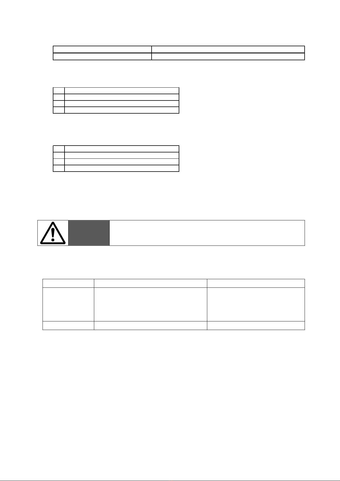
パッケージ内容の確認
5ページ: 設置 8ページ: 仕様 9ページ: オプション 参照
2. 特徴
使用可能な照明
モリテックス製MG-Waveの照明のうち、以下の照明がご使用になれます。 ※1
MLEP-A035W3LRD : 3ピン / 0.35 [A] 照明
MLEP-A070W3LRD : 3ピン / 0.70 [A] 照明
出力
3 チャンネルの出力が可能です。
※ 各チャンネル独立でコントロール可能です。
マニュアル調整機能
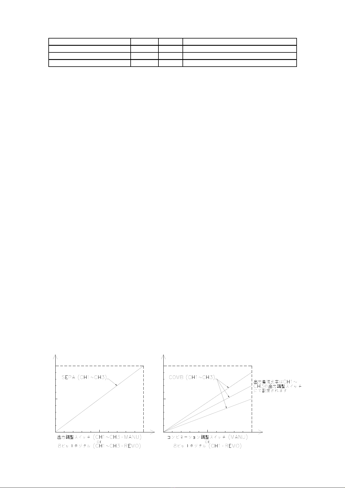
前面パネルの出力調整スイッチで出力を調整し、接続された LED 照明を調光することが可能です。
※ 各チャンネル独立でコントロール可能です。(SEPA 時)
※ MANU/REMO スイッチが、MANU の時のみ有効です。
※ COARSE で粗調整が、FINE で微調整が可能です。
※ 0,1,・・・・,E,F は 16 進数です。
※ (COARSE, FINE)が(0,0)で MIN、(F,F)で MAX になります。
※ (0,0)から(0,5)程度まで、出力しない範囲があります。
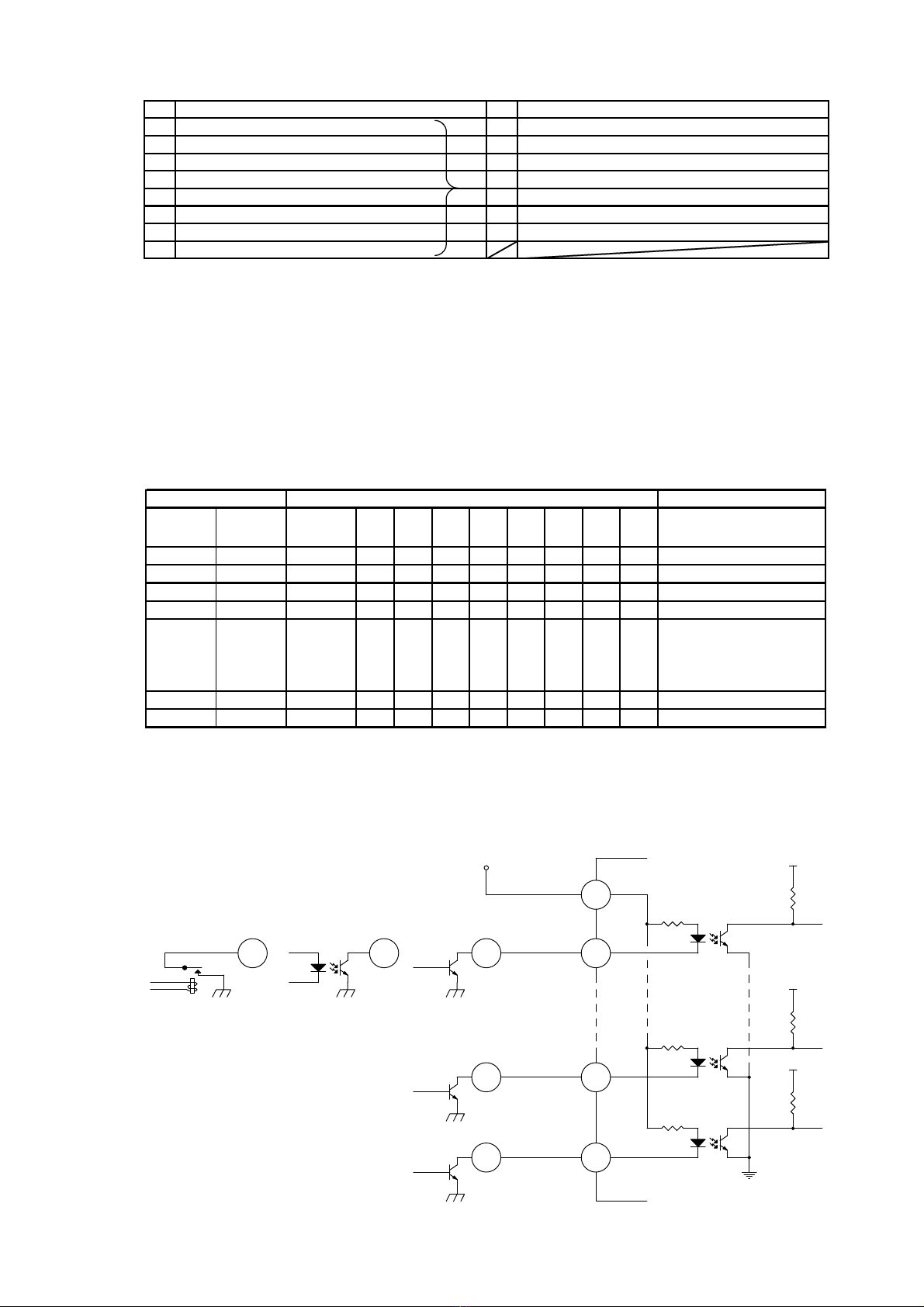
リモート調整機能
後面パネルの外部信号接続コネクタに8ビットのデジタル信号を入力する事で出力を調整し、接続された
LED 照明を調光することが可能です。
※ 各チャンネル独立でコントロール可能です。(SEPA 時)
※ MANU/REMO スイッチが、REMO の時のみ有効です。
コンビネーション機能
前面パネルの COMB 調整スイッチまたは CH1 の8ビットデジタル信号により、設定した出力電流比率を変
えずに、接続された LED 照明を 3 チャンネル同時に調光することが可能です。
※ SEPA/COMB スイッチが、COMB の時のみ有効です。
※ 出力電流比率は、MANU/REMO に関係なく、前面パネルの CH1~CH3 の出力調整スイッチにて設
定します。
※ MANU 時、前面パネルの COMB 調整スイッチにて調整できます。
※ REMO 時、CH1 の8ビットデジタル信号にて調整できます。
部品名 数量 単位 備考
本体 1 個 -
ACコードセット 1 本 ※
取扱説明書 1 冊 本書
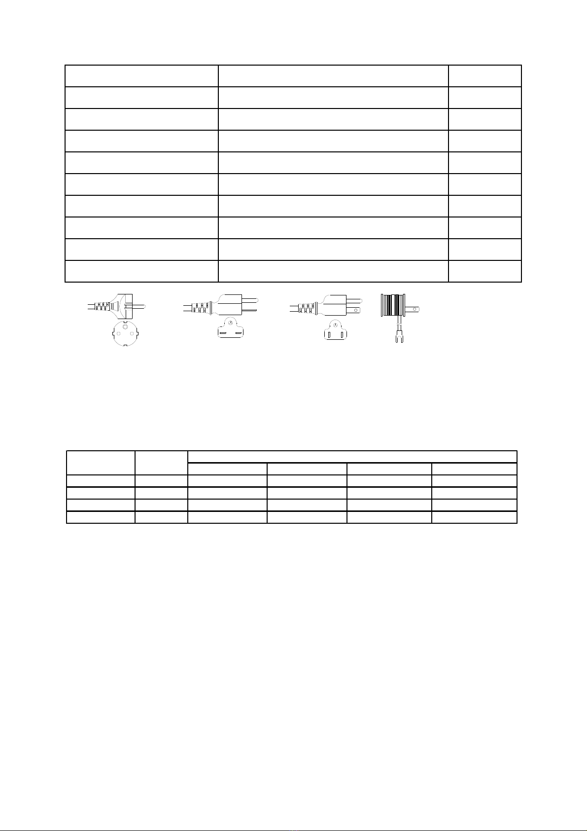
※ ご購入時の型番の接尾辞により、『-100V』には『MC-AC100A-2.0M』が、『-200V』には
『MC-AC200A-2.0M』が添付されております。電源接続前に、主電源コードが使用される
国の法律・規格を満足し、電源電圧・温度の仕様条件に合っているか確認してください。

様式 : HJDS00030A 4 A09634B5000501B-003
出力 ON/OFF 機能
外部コネクタに信号を入力する事により、接続されたLED照明を消灯できます。
※ 各チャンネル独立でコントロール可能です。
※ MANU/REMO、SEPA/COMB に関係なく動作します。
警告
※1 指定された照明以外は接続しないでください。
3. 設置
基本構成について
・ 本装置と MCEP 照明を接続することでご使用になれます。 3 ページ:特徴 参照
・ 外部信号接続コネクタに信号を接続してご使用になれます。
※ オプションで、外部接続ケーブル・照明用中継ケーブルもあります。(MC-EXC-02, M-RCB3**L)
各部の名称と働き

様式 : HJDS00030A 5 A09634B5000501B-003
① 電源スイッチ 『 I 』側にすると、電源が入ります。
② パワーインジケータ 電源が入っている時に点灯します。
③ SEPA/COMB スイッチ 出力調整のセパレートとコンビネーションを設定します。
④ MANU/REMO スイッチ 出力調整のマニュアルとリモートを設定します。
⑤ コンビネーション調整スイッチ コンビネーションの出力を調整します。
⑥ 出力調整スイッチ マニュアルの時に、出力を調整します。
⑦ 照明用出力コネクタ 照明を接続します。
⑧ 外部信号接続コネクタ 外部機器を接続するためのコネクタです。
⑨ AC インレット AC ケーブルを差し込みます。
⑩ 側面空気穴 冷却用の空気穴です。
⑪ ゴム足 オプションの取付ブラケットを使用するときは外します。
⑫ チャンネル表示 表示の下にチャンネルごとの部品が配置されています。
※ 図は MLEP-A070W3LRD のものです。
※ ⑩は MLEP-A035W3LRD にはありません。
設置
ゴム足を下にした水平設置。
※ 設置後、本体周囲に 10mm 以上の空間を確保してください。
※ 電源スイッチの ON/OFF が容易に行える場所、あるいはインレットまたはプラグが容易に取り外せる場
所に設置してください。
※ 感電保護 : クラスⅠ機器。
※ 使用する際には、入力する AC 電圧と使用する国や地域の規格に適合した適切な電源コードをご使
用ください。
※ 以下の構成にて EU 指令/EN 規格に適切に適合することができます。
長さ:3m 以下 端子:L/N/PE
クラスⅠ機器用プラグにて保護接地端子に接続
オプションの MC-AC200A-2.0M は上記規格に適合しております。
4. 外部装置との接続
警告
・接続する機器の一次側の回路から強化絶縁以上で分離された SELV 回路
以外は接続しないでください。
・外部信号接続ケーブルは必ずシールド線を使用し、長さは 2 m 以下
を推奨します。(オプション: MC-EXC-02)
・過大な入力や過負荷はしないでください。
外部信号接続コネクタについて (EXT)
型式
HDAB-15S(05) : コネクタ(メス) (HRS製)
HDA-CTH : コネクタケース (HRS製)
HDAB-15P(05)(オス)
(HRS製)
固定ネジ M2.6
外部ケーブル側コネクタ
または 同等品
本体側コネクタ

様式 : HJDS00030A 6 A09634B5000501B-003
ピンアサイン
真理値表
入力回路例
№ 名 称 № 名 称
18bitデジタル入
力
20
(
LSB
)
9 COMMON (+) ※1
28bitデジタル入
力
2110 出力ON/OFF信号(入力) ※2
38bitデジタル
入力
2211 NC
48bitデジタル入
力
23※3 12 NC
58bitデジタル入
力
2413 NC
68bitデジタル
入力
2514 NC
78bitデジタル
入力
2615 NC
88bitデジタル入
力
27
(
MSB
)
※1
※2
※3
・ オープンコレクタ入力が可能です。
REMOのみ有効です。(出力の状態については真理値表を参照)
・ ”L”入力時 1回路あたりの電流 COMMON 5 V時 : 1 mA 、 COMMON 24 V時 : 6 mA
・ MANU/REMOに関係なく動作します。
・ オープンコレクタ入力が可能です。
電流 COMMON 5 V時 : 1 mA 、 COMMON 24 V時 : 6 mA
”H”(COMMON)入力またはオープン時 ・・・・・ 出力ON
・ 使用中の入力変動は行わないでください。
”L”入力時 ・・・・・・・・・・・・・・・・・・・・・・・・・・・ 出力OFF
5 V から 24 Vに対応しています。
5 V
47k
1
5 V - 24 V
8
47k
MSB
3.9k
A
10
COMMON
ON/OFF
A
A
A A LSB
5 V
5 V
9
3.9k
3.9k
47k
Photo-coupler TransistorRelay
出力
COARSE FINE
出力
ON/OFF
Bit
2
7
Bit
2
6
Bit
2
5
Bit
2
4
Bit
2
3
Bit
2
2
Bit
2
1
Bit
2
0
出力(照明)の状態
× × L ×××××××× 出力OFF
× × H ×××××××× 出力ON
00H LLLLLLLL MIN出力
01H LLLLLLLH
0 2 H LLLLLLHL
: : : :::::::: :
: : : :::::::: :
F D H HHHHHHLH
FEH HHHHHHHL
FFH HHHHHHHH MAX出力
入力 H : High(COMMON)入力 または 入力オープン
L:Low 入力
×:H ・ L 任意
(COARSE,FINE) が (0,5) 程度まで点灯しない範囲があります。
出力調整スイッチ 外部信号 COMMON +

様式 : HJDS00030A 7 A09634B5000501B-003
出力コネクタについて (MG-Wave の MCEP 照明用、各チャンネル共通: OUT1, OUT2, OUT3)
型式
ピンアサイン
MLEP-A035W3LRD
MLEP-A070W3LRD
5. メンテナンスについて
警告
・お手入れをする時は、必ず電源を切り、外部機器との接続を全てはずして
から行ってください。
・絶対に分解はしないでください。
・ 本体の汚れは、乾いた布でふき取ってください。
・ 汚れがひどい時は、布に薄めた中性洗剤を含ませ、かたくしぼってから汚れをふき取ってください。
故障かな?と思ったら
症状 原因 対策
照明が点灯しない
照明が暗い
・照明は正しく接続されていますか?
・MANU/REMO の設定は正しいですか?
・出力調整はされていますか?
・外部機器が正しく接続されていますか?
・照明を正しく接続してください
・MANU/REMO を確認してください
・調整してください
・外部機器を正しく接続してください
ON/OFF しない ・外部機器が正しく接続されていますか? ・外部機器を正しく接続してください
本体側出力コネクタ 照明側コネクタ
SMP-03V-BC (JST製) SMR-03V-B (JST製) または 同等品
№ 名 称
1NC
2 電流出力 (+) ※1
3 電流出力 (-) ※1
※1
オプション: M-RCB3**L
出力電圧は 5.5 [V] 以下です。
№ 名 称
1 電流出力 (+) ※1
2NC
3 電流出力 (-) ※1
※1
オプション: M-RCB3**L
出力電圧は 5.5 [V] 以下です。

様式 : HJDS00030A 8 A09634B5000501B-003
6. 仕様
MLEP-A035W3LRD MLEP-A070W3LRD
※1
0.14/0.09 [A] typ.
at AC 100 / 240 [V]
0.25/0.14 [A] typ.
at AC 100 / 240 [V]
※2
0.35 [A] (1チャンネルあたり) 0.70 [A] (1チャンネルあたり) ※3
IP 40 (EN 60529) IP 30 (EN 60529) ※4
※5
※1
※2
※3
※4
※5
直径1mm(MLEP-A070W3LRDは2.5mm)以上の物体が内部に侵入しません。水の浸入に対して保護され
ていません。
質量
Low Voltage: EN61010-1
EMC: EN55011, EN61000-3-2, EN61000-3-3, EN61000-6-2
欧州整合規格
約 1.4 [kg]
感電保護
冷却方式
保護等級
外形寸法
(オプションのMC-AC200A-2.0MはCEマーキングに適合しております。)
MLEP-A035W3LRD、MLEP-A070W3LRD及びオプション品は、上記ヨーロッパ規格への適合をCEマーキ
ングの宣言書にて宣言しております。また本体をCE適合にて使用する場合、CEマーキングに適合したAC
ケーブルをご使用ください。
使用する際には、入力するAC電圧/電流と使用する国や地域の規格に適合した適切な電源コードをご使
用ください。(オプションにて製品に添付されているケーブルの型式をご確認ください。)
環境条件
保存温度/湿度
設置方法
リモートコントロール
出力制御方式
出力形態
出力調整機能
出力可変範囲
入力突入電流
出力数
出力電圧
出力電流
型式
入力電圧
入力電流
入力周波数
DC連続出力
有り
マニュアル/リモート
セパレート/コンビネーション
0 - 100 [%]
-20 ~ 75 [℃] / 20 ~ 85 [%RH] (結露なきこと)
有り
8ビットデジタル出力調整 / 出力ON/OFF制御
50/60 [Hz]
20 [A] max. at AC 100 [V]
40 [A] max. at AC 240 [V]
3チャンネル出力
Max 5.5 [V] (出力オープン時)
指定電流の照明以外ご使用になれません。
定電流制御
ゴム足を下にした水平設置
自然空冷
W150×H75×D150 (突起部除く)
屋内使用
最高高度 : 2000 m
温度 : 0 ℃ ~ 45 ℃
湿度 : 31 ℃ まで 80 % RH、40 ℃ で 50 % RH に線形に低下
主電源電圧変動が公称電圧の ± 10 % 以内
設置カテゴリ Ⅱ
汚染度2
クラスⅠ機器
コールドスタート時。
AC 100 - 240 [V] (本体・ACインレット)

様式 : HJDS00030A 9 A09634B5000501B-003
オプション
オプション品 ピンアサイン
・KE タイプ
6 ページの標準ピンアサイン参照。
表1
8ビット論理 8ビットオープン ON/OFF論理 ON/OFFオープン
標準 (KC) + L 消灯 MAX点灯 L 消灯 点灯
KE + L 点灯 消灯 L 消灯 点灯
AC - H 消灯 MAX点灯 H 消灯 点灯
AE - H 点灯 消灯 H 消灯 点灯
出力(照明)の状態
※ COMMON +: 外部電源 +, COMMON -: 外部電源 -
※ 論理 H: 外部電源 +, 論理 L: 外部電源 -
Type COMMON
CE適合 ○:Yes
×:No
照明用中継ケーブル
(別売り)
※1 1m,2m:○
3m:× ※6
AC 200 Vケーブル
(別売り)
MC-AC200A-2.0M (2mのみ) ※2 ○
AC 200 Vケーブル
(別売り)
MC-AC200B-2.0M (2mのみ) ※3 ×
AC 100 Vケーブル
(別売り)
MC-AC100A-2.0M (2mのみ) ※4 ×
外部接続ケーブル
(別売り)
MC-EXC-02 (2m・片端バラ) ※1 ○
取付ブラケット
(別売り)
LBK-002 (底面取付タイプ) -
8bitデジタル入力 KE改造
(受注生産) 『-KE』
論理反転 ※5 ○
8bitデジタル入力 AE改造
(受注生産) 『-AE』
COMMON極性反転 ※5 ○
8bitデジタル入力 AC改造
(受注生産) 『-AC』
COMMON極性反転 および 論理反転 ※5 ○
※1 長さ違いはお問い合わせください。
※2 ※3 ※4 アダプタ
( 国内のみ使用可 )
CE <PS>E <PS>E/UL/CSA <PS>E
AC 250Vまで AC 250Vまで AC 125Vまで
(使用する国や地域の規格に適合したケーブルを使用してください。)
(ケーブル仕様の詳細は別途弊社までお問い合わせください。)
※6 3m延長ケーブルはCE適合外です
名称 型式
M-RCB3**L (3ピン用延長ケーブル)
** 2桁は長さ (01=1m、02=2m、03=3m)
※5 表1 参照 (型式末尾に-KE/-AE/-AC)

様式 : HJDS00030A 10 A09634B5000501B-003
・AC/AE タイプ
オプション品 真理値表
・KE タイプ
・AC タイプ
№ 名 称 № 名 称
18bitデジタル
入力
20
(
LSB
)
9COMMON (-) ※1
28bitデジタル
入力
2110 出力ON/OFF信号(入力) ※2
38bitデジタル入
力
2211 NC
48bitデジタル入
力
23※3 12 NC
58bitデジタル
入力
2413 NC
68bitデジタル
入力
2514 NC
78bitデジタル
入力
2615 NC
88bitデジタル
入力
27
(
MSB
)
※1
※2
※3 REMOのみ有効です。(出力の状態については真理値表を参照)
・ ”H”入力時 1回路あたりの電流 H = 5 V時 : 1 mA 、 H = 24 V時 : 6 mA (電圧入力)
”L”(COMMON)入力またはオープン時 ・・・・・ 出力ON
・ MANU/REMOに関係なく動作します。
”H”入力時 ・・・・・・・・・・・・・・・・・・・・・・・・・・・ 出力OFF
電流 H = 5 V時 : 1 mA 、 H = 24 V時 : 6 mA (電圧入力)
COMMONに対し、各入力ピンは5 V から 24 Vに対応しています。
・ 使用中の入力変動は行わないでください。
出力
COARSE FINE
出力
ON/OFF
Bit
2
7
Bit
2
6
Bit
2
5
Bit
2
4
Bit
2
3
Bit
2
2
Bit
2
1
Bit
2
0
出力(照明)の状態
× × L ×××××××× 出力OFF
× × H ×××××××× 出力ON
00H HHHHHHHH MIN出力
01H HHHHHHHL
0 2 H HHHHHHLH
: : : :::::::: :
: : : :::::::: :
F D H LLLLLLHL
FEH LLLLLLLH
FFH LLLLLLLL MAX出力
入力 H : High(COMMON)入力 または 入力オープン
L:Low 入力
×:H ・ L 任意
(COARSE,FINE) が (0,5) 程度まで点灯しない範囲があります。
出力調整スイッチ 外部信号 COMMON +
出力
COARSE FINE
出力
ON/OFF
Bit
2
7
Bit
2
6
Bit
2
5
Bit
2
4
Bit
2
3
Bit
2
2
Bit
2
1
Bit
2
0
出力(照明)の状態
× × H ×××××××× 出力OFF
× × L ×××××××× 出力ON
00L HHHHHHHH MIN出力
01L HHHHHHHL
0 2 L HHHHHHLH
: : : :::::::: :
: : : :::::::: :
F D L LLLLLLHL
FEL LLLLLLLH
FFL LLLLLLLL MAX出力
入力 H:High入力
L : Low(COMMON)入力 または 入力オープン
×:H ・ L 任意
(COARSE,FINE) が (0,5) 程度まで点灯しない範囲があります。
出力調整スイッチ 外部信号 COMMON -

様式 : HJDS00030A 11 A09634B5000501B-003
・AE タイプ
オプション品 入出力回路例
・KE タイプ
6 ページの標準入出力回路例参照。
・AC/AE タイプ
5 V - 24 V
5 V - 24 V
A
5 V - 24 V
A
5 V
47k
1
5 V - 24 V
8
47k
MSB
3.9k
A
10
TransistorPhoto-coupler
Relay
COMMON
ON/OFF
A A LSB
5 V
5 V
9
3.9k
3.9k
47k
5 V - 24 V
出力
COARSE FINE
出力
ON/OFF
Bit
2
7
Bit
2
6
Bit
2
5
Bit
2
4
Bit
2
3
Bit
2
2
Bit
2
1
Bit
2
0
出力(照明)の状態
× × H ×××××××× 出力OFF
× × L ×××××××× 出力ON
00L LLLLLLLL MIN出力
01L LLLLLLLH
0 2 L LLLLLLHL
: : : :::::::: :
: : : :::::::: :
F D L HHHHHHLH
FEL HHHHHHHL
FFL HHHHHHHH MAX出力
入力 H:High入力
L : Low(COMMON)入力 または 入力オープン
×:H ・ L 任意
(COARSE,FINE) が (0,5) 程度まで点灯しない範囲があります。
出力調整スイッチ 外部信号 COMMON -

様式 : HJDS00030A 12 A09634B5000501B-003
外形寸法
図は MLEP-A070W3LRD のものです。
MLEP-A035W3LRD には、側面の空気孔は有りません。

様式 : HJDS00030A 13 A09634B5000501B-003
7. その他
1. 装置および装置の部品は一般廃棄物として処理せずに、必ず分別してください。
2. 装置および装置の部品を廃棄する前に、処理方法または回収方法を必ず弊社までお問い合わせく
ださい。
3. 以下のシンボルは、廃電気・電子機器の分別回収を意味しています。装置および装置の部品は一般
廃棄物として処理しないでください。
4. 本装置は、2002/96/EC 指令(廃電気・電子機器の処理指令: Waste EIectrical and EIectronic
Equipment)に該当いたします。当指令においては、環境の保護・保存、人体の健康への保護、天然資源
の利用を慎重かつ合理的に行うことを最重要としています。本趣旨に基づき、取扱説明書による装置およ
び装置部品の廃棄によって、お客様が環境保全に対する責任を負うことをご承知ください。
5. 本装置は、2002/95/EC 指令(RoHS 指令)適合しております。
または
6. 装置内の危険物質は以下になります。
Lead (Pb): 15mg: Solder of Printed Wiring Boards
《MEMO 》

様式 : HJDS00030A 14 A09634B5000501B-003
《付録》
・不明な点はご相談ください。
補修部品の詳細やアフターサービスについてご不明な点は、お買い求めの販売店または弊社営業所に
遠慮なくお問い合わせください。
・修理を依頼される場合は、次のことをお知らせください。
機 種 : MLEP-A035W3LRD / MLEP-A070W3LRD
製 造 番 号 : 本体に記載
ご 購 入 日 : 年 月 日
故 障 状 況 : 出来るだけ詳しく
お名前(法人名または個人名)、ご住所、電話番号、e-mail アドレス

様式 : HJDS00030A 15 A09634B5000501B-003
English
Power source unit for MCEP Illuminators of MG-Wave constant current Illuminators
MLEP-A035W3LRD
MLEP-A070W3LRD
with or without suffix: -KE, -AE, -AC
INSTRUCTION MANUAL
- Table of Contents -
Table of Contents 15 4. Connections 19
1. Introduction 15 External Signal Connector 19
Precautions for Correct Use 16 Connector for Illuminator 21
Warranty 16 5. Maintenance 21
Confirming Package Contents 17 Troubleshooting 21
2. Features 17 6. Specifications 22
3. Installation 18 Optional Items 23
Basic System Configuration 18 Dimensions 26
Equipment Control 18 7. Others 27
Installation 19 《Appendix》 28
1. Introduction
Please read this instruction manual carefully, before starting operation. Keep this book for the whole
product lifetime, and store it in a place easily accessible.
Meanings of Warning Symbol The following warning symbol is used in this manual.
Be sure to fully understand the contents of the warning.
WARNING
This warning marking indicates a potentially hazardous situation, which can
result in hazard to the operator or damage to the unit, if the directions of this
Instruction Manual are not followed.

様式 : HJDS00030A 16 A09634B5000501B-003
Precautions for Correct Use
WARNING
Use this product only after understanding contents of the following:
・ If using this product in combination with other apparatuses, please confirm the correctness/compatibility
of the connection with these external apparatuses (especially regarding insulation requirements).
・ If using this product in combination with other apparatuses, please confirm any standards, codes, or
regulations that apply to the combination of the apparatuses.
・ If using this product in combination with other apparatuses, please confirm that installation, connection
and use within the entire system is according to the specification of this product (as described in this
Instruction Manual) and according to those of all other apparatuses.
・ Never use the product for an application involving serious risks to life or property as long as the whole
system is not equipped with appropriate safety measures of the relevant safety category.
・ Please install this product in such a way that water cannot sprinkle into it.
・ Whenever some matter/dirt stuck to the product, please completely wipe it off, using a dry cloth.
・ This product needs periodical inspection and exchange of maintenance parts.
・ Whenever trouble occurs, please request repair to MORITEX, and do not dismantle the product by your own.
Other precautions
・ When a customer wants to scrap the product, the whole equipment has to be disposed as industrial
waste, according to laws and ordinances of the customer’s area.
・ Dimensions and Weights are reference.
・ Specifications of the product (or accessories or optional items) may be changed at any time based on
improvements and other reasons without any notice.
・ Please inquire to MORITEX about indistinct contents.
Warranty
The term of a warranty
The warranty of this product lasts for one year from the date of purchase. In case of product failure within
one year from the date of purchase, and there is no doubt on the correct utilization of the product,
according to this instruction manual the unit will be repaired at no charge.
Limitations of warranty
When inconvenience due to our responsibility occurs to a product during the warranty period, the part
that has trouble will be changed to a new part, or repaired, free of charge. But, if the cause of the trouble
fits to the following, the product is out of warranty.
・ The cause of the trouble is of such technical nature that could not be foreseen at the time of shipment.
・ The trouble is not caused by this product.
・ The trouble is caused by modification or repair by a person other than MORITEX.
・ The trouble is caused by unauthorized use, not conforming to this Instruction Manual.
・ The trouble is caused by the inappropriate handling such as a drop or a shock.
・ The trouble is repaired by MORITEX at on-site service.
・ The trouble is caused by a condition out of our responsibility such as a natural disaster or pollution.
・ The cause of the trouble can not be identified by MORITEX.
MORITEX shall not be responsible for indirect or consequential damages, in any way related to this
product. The responsibility of MORITEX for any act shall not exceed the price of this product. The
warranty is limited to business and use in Japan. Please inquire to MORITEX about warranty overseas.

様式 : HJDS00030A 17 A09634B5000501B-003
Confirming Package Contents
Refer to Page 19: Installation, Page 22: Specifications, Page 23: Optional Items
2. Features
Applicable Illuminators
Requirements for applicable MG-Wave Illuminators (made by MORITEX) : ※1
MLEP-A035W3LRD: Illuminator of 0.35 [A] /3pin type
MLEP-A070W3LRD: Illuminator of 0.70 [A] /3pin type
Output
Number of output channels: 3 channels
※ Each output channel can be controlled separately.
Manual illuminance adjustment function
It is possible to adjust the illuminance of the Illuminator by using the Output Control SW on the front-panel.
※ It is possible to control each channel separately (at SEPA-mode).
※ Manual adjustment of the illuminance is possible when selecting MANU mode (MANU/REMO SW)
※ Hexadecimal control: 0,1,・・・・,E,F
※ (COARSE, FINE): (0,0) = MIN; (F,F) = MAX
※ Range between (0,0) and about (0,5) does not turn on the Illuminator.
Remote illuminance adjustment function
It is possible to adjust the illuminance of the Illuminator by inputting an 8bit digital signal to the External
Signal Connector on the rear-panel.
※ It is possible to control each channel separately (at SEPA-mode).
※ Remote adjustment of the illuminance is possible when selecting REMO mode (MANU/REMO SW)
Combined control function
It is possible to collectively adjust the illuminance of all 3 illuminators without changing the output current
ratio by inputting an 8bit digital signal to the External Signal Connector of CH1 or using the Combination
Control SW on the front-panel.
※ Combined control is possible when the COMB-mode is selected (SEPA/COMB SW).
※ It is possible to set the output current ratio, using the Output Control SW of CH1 to CH3 regardless
of the MANU / REMO setting.
Part name Quantity Unit Notes
Main body 1 piece -
Power Supply Cord Set 1 piece ※
Instruction Manual 1 book This book
※ 『MC-AC100A-2.0M』 is attached to 『-100V』 model. 『MC-AC200A-2.0M』 is attached
to 『-200V』 model. (It depends on the suffix of the model that was purchased.)
Before connection to the power supply, please check the conformity of the specifications
of the Power Supply Cord Set with the laws and standards of your country as well as the
correct power and temperature rating.

様式 : HJDS00030A 18 A09634B5000501B-003
※ If MANU-mode is selected, combined control is possible using the Combination Control SW on the
front-panel.
※ If REMO-mode is selected, combined control is possible by inputting an 8bit digital signal to the
External Signal Connector of CH1.
Output ON/OFF function
It is possible to turn off the Illuminator by inputting a relevant signal to the External Signal Connector.
※ It is possible to control each channel separately.
※ Operation of this function is possible regardless of the MANU/REMO and SEPA/COMB setting.
WARNING
※1 Do not connect anything to output except designed illuminator.
3. Installation
Basic System Configuration
・ This Unit is dedicated for use with/for connection to the MCEP Illuminator. Refer to Page 3: Features
・ For external control, it is possible to connect an external apparatus via the External Signal Connector.
※ The cables for connection to the EXT Connector and to the Illuminator are supplied as Optional Item
(MC-EXC-02, M-RCB3**L).
Equipment Control

様式 : HJDS00030A 19 A09634B5000501B-003
① Power SW Tilt to "I" side for turning on power.
② Power indicator LED illuminates when power supply is ON.
③ SEPA/COMB SW Switch for selecting between separate or combination control.
④ MANU/REMO SW Switch for selecting manual or remote control.
⑤ Combination control SW Switch for combined adjustment of output-control.
⑥ Output control SW Manual adjustment switch for output-control.
⑦ Connector for illuminator:
OUT1/OUT2/OUT3
Terminal for connection to the Illuminator.
⑧ External signal connector:
EXT1/EXT2/EXT3
Terminal for external control.
⑨ MAINS supply Inlet for connecting power supply cable.
⑩ Air Hole Air hole for cooling.
⑪ Rubber feet Take them off, when using with the optional installation bracket.
⑫ Indication of channels Indicates channel number for terminals below.
※ Drawings show the MLEP-A070W3LRD unit.
※ MLEP-A035W3LRD does not have ⑩.
Installation
Install horizontally on the rubber feet at the bottom of the unit.
※ Install the unit in such a way, that adequate space is left free for ventilation. Keep space of at least
10mm around the main body.
※ Be sure to install the unit in such a way that the Power Switch can be operated easily and the Mains
Plug can be pulled out without hindrance, in case of emergency.
※ Protection Class: Class I equipment.
※ Before using this product, please provide an appropriate power supply cord set conforming to the
input power ratings and to the relevant standards of the area where you use this product.
※ The power supply cord set shall have following configurations:
Length: < 3 m; Conductors: L / N / PE; Class I type mains plug with reliable connection to the
Protective Earthing Conductor of the Building Installation.
Optional Item MC-AC200A-2.0M does comply with these requirements.
4. Connections
WARNING
・Only SELV circuits, which have reinforced insulation to their equipment
primary circuit, may be connected to the unit.
・For connection to the External Signal Connector, use a shielded cable with
a recommended length of less than 2 m (Optional item: MC-EXC-02)
・Please do not excessive input or overload.
External signal connector (EXT)
Model
HDAB-15S(05) : connector(female) (made by HRS)
HDA-CTH : connector case (made by HRS)
Terminal of the Unit Connector of the cable
HDAB-15P(05)(male)
(made by HRS)
Screws: M2.6 or its equivalent

様式 : HJDS00030A 20 A09634B5000501B-003
Pin assignment
Truth table
Example of input circuit
№ Identification № Identification
18bit di
g
ital in
p
ut 20
(
LSB
)
9 COMMON (+) ※1
28bit di
g
ital in
p
ut 2110 Input ON/OFF signal ※2
38bit di
g
ital in
p
ut 2211 NC
48bit di
g
ital in
p
ut 23※3 12 NC
58bit di
g
ital in
p
ut 2413 NC
68bit di
g
ital in
p
ut 2514 NC
78bit di
g
ital in
p
ut 2615 NC
88bit di
g
ital in
p
ut 27
(
MSB
)
※1
※2
※3
・ Open-Collector type input is possible.
Only for REMO Control (Refer to Truth Table, shown below)
・ Input “L”, Current per circuit: 1 mA (Common: 5 V), 6 mA (Common: 24 V)
・ Operation possible regardless from MANU/REMO selection.
・ Open-Collector type input is possible.
Current: 1 mA (Common: 5 V), 6 mA (Common: 24 V)
Input ”H”(COMMON) or Input open ・・・・・ Output ON
・ Please do not change the input voltage during operation.
Input ”L” ・・・・・・・・・・・・・・・・・・・・・・・・・・・ Output OFF
It is possible to input a voltage between 5V and 24V.
5 V
47k
1
5 V - 24 V
8
47k
MSB
3.9k
A
10
COMMON
ON/OFF
A
A
A A LSB
5 V
5 V
9
3.9k
3.9k
47k
Photo-coupler TransistorRelay
Output
COARSE FINE
Output
ON/OFF
Bit
2
7
Bit
2
6
Bit
2
5
Bit
2
4
Bit
2
3
Bit
2
2
Bit
2
1
Bit
2
0
State of output
(Illuminator)
× × L ×××××××× Output OFF
× × H ×××××××× Output ON
00H LLLLLLLL Output MIN
01H LLLLLLLH
0 2 H LLLLLLHL
: : : :::::::: :
: : : :::::::: :
F D H HHHHHHLH
FEH HHHHHHHL
FFH HHHHHHHH Output MAX
Input H : Input High(COMMON) or Input open
L:Input Low
× : H ・ L state not relevant
(COARSE,FINE): Range between (0,0) and about (0,5) does not turn on the Illuminator.
External signals COMMON +
Output control SW
This manual suits for next models
1
Table of contents
Other Moritex Schott Power Supply manuals
Popular Power Supply manuals by other brands

BCP
BCP PUOOUBZ How to install

Keithley
Keithley Series 2200 user manual

Brookstone
Brookstone Handcrank Power Supply owner's manual

Honeywell Home
Honeywell Home PS1201A00 installation instructions

Whelen Engineering Company
Whelen Engineering Company CSP69024 installation guide

Rohde & Schwarz
Rohde & Schwarz HMC804 user manual