manuals.online logo
Brands
  1. Home
  2. •
  3. Brands
  4. •
  5. Morris Products
  6. •
  7. Measuring Instrument
  8. •
  9. Morris Products 57250 User manual

Morris Products 57250 User manual

OPERATING INSTRUCTION
MODEL 57250
AC CLAMP METER
Safety
International Safety Symbols
This symbol, adjacent to another symbol or terminal, indicates the user must refer to
the manual for further information.
This symbol, adjacent to a terminal, indicates that, under normal use, hazardous
voltages may be present
Double insulation
SAFETY NOTES
•Do not exceed the maximum allowable input range of any function
•Do not apply voltage to meter when resistance function is selected.
•Set the function switch OFF when the meter is not in use.
WARNINGS
•Set function switch to the appropriate position before measuring.
•When measuring volts do not switch to current/resistance modes.
•Do not measure current on a circuit whose voltage exceeds 240V.
•When changing ranges using the selector switch always disconnect the test leads from the
circuit under test.
•Do not exceed the maximum rated input limits.
CAUTIONS
Improper use of this meter can cause damage, shock, injury or death. Read and understand
this user manual before operating the meter.
Always remove the test leads before replacing the battery.
Inspect the condition of the test leads and the meter itself for any damage before operating the
meter. Repair or replace any damage before use.
Use great care when making measurements if the voltages are greater than 25VAC rms or
35VDC. These voltages are considered a shock hazard.
Remove the battery if the meter is to be stored for long periods.
Always discharge capacitors and remove power from the device under test before performing
Diode, Resistance or Continuity tests.
•Voltage checks on electrical outlets can be difficult and misleading because of the uncertainty
of connection to the recessed electrical contacts. Other means should be used to ensure that
the terminals are not "live".
•If the equipment is used in a manner not specified by the manufacturer, the protection
provided by the equipment may be impaired.
Input Limits
Function
Maximum Input
A AC
400A
V DC, V AC
600V DC/AC
Resistance, Diode, Continuity Test
250V DC/AC
Meter Description
1. Current clamp
2. Clamp trigger
3. Rotary Function swith
4. LCD display
5. MAX Hold button
6. Data Hold button
7. Mode select button
8. Range select button
9. Backlight button
10. COM input jack
11. V Ωjack
12. Battery Cover
1. AC DC AC (alternating current) and DC (direct currrent)
2. Minus sign
3. 1.8.8.8 2000 count (0 to 1999) measurement reading
4. AUTO AutoRange mode
5. MAX MAX Hold mode
6. Diode test mode
7. •))) Audible Continuity
8. HOLD Data Hold mode
9. BAT Low Battery icon
10. ℃,℉,m,V,A,K,M,ΩUnits of measure list
Specifications
Function
Range & Resolution
Accuracy (% of reading)
AC Current
2.000 AAC
± (2.5% + 10 digits)
20.00 AAC
± (2.5% + 4 digits)
200.0 AAC
400 AAC
± (3.0% + 4 digits)
DC Voltage
200.0 mVDC
± (0.5% + 5 digits)
2.000 VDC
± (1.2% + 3 digits)
20.00 VDC
200.0 VDC
600 VDC
± (1.5% + 3 digits)
AC Voltage
200.0 mVAC
± (1.5% + 30 digits)
2.000 VAC ± (1.5% + 3 digits)
20.00 VAC
200.0 VAC
600 VAC
± (2.0% + 4 digits)
Resistance
200.0 Ω
± (1.0% + 4 digits)
2.000KΩ
± (1.5% + 2 digits)
20.00KΩ
200.0KΩ
2.000MΩ
± (2.0% + 3 digits)
20.00MΩ
± (3.0% + 5 digits)
Note: No Auto ranging & 200mV AC Voltage Range.
kM
BAT
Ω
Ω
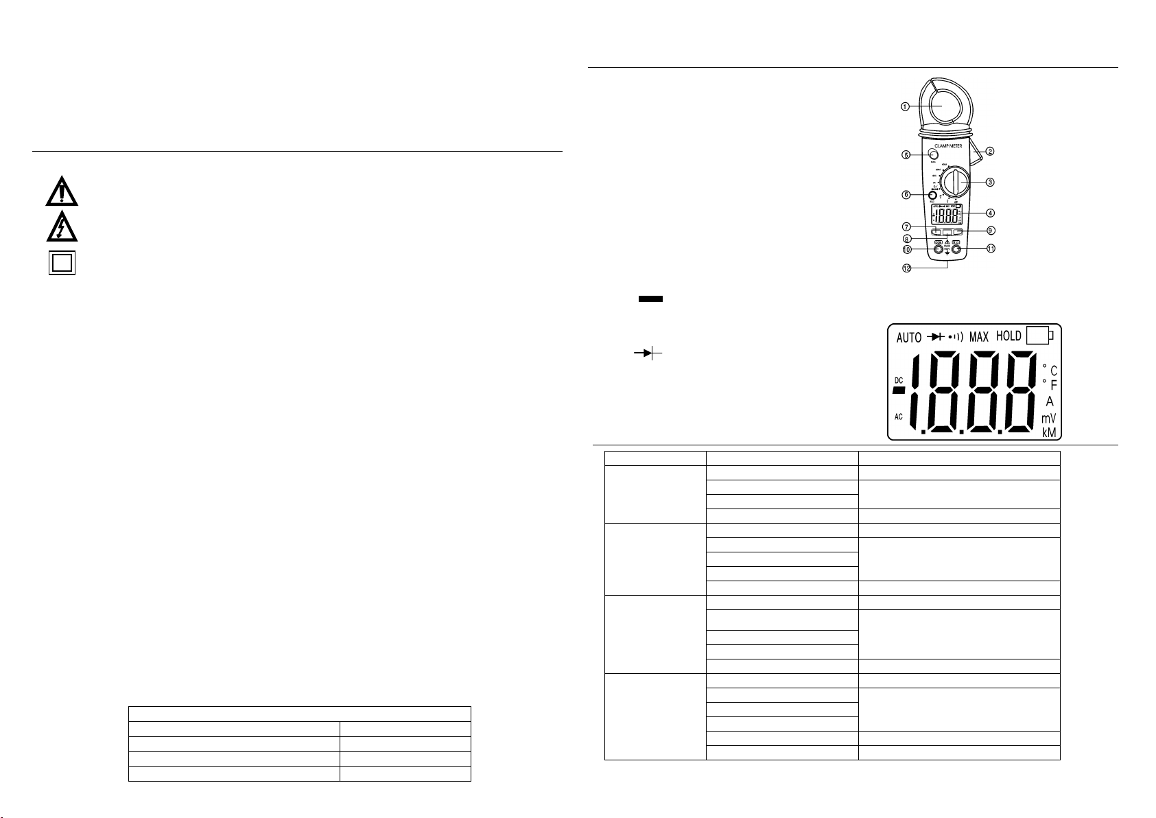
Clamp size Opening 0.9" (23mm) approx
Diode Test Test current of 0.3mA typical; Open circuit voltage 1.5V DC typical.
Continuity Check Threshold <120Ω; Test current < 1mA
Low Battery Indication “BAT” is displayed
Overrange Indication “OL“ is displayed
Measurements Rate 2 per second, nominal
Input Impedance 7.8MΩ(VDC and VAC)
Display 3-1/2 digits (2000 counts) LCD
AC Current bandwidth 50/60Hz (AAC)
AC Voltage bandwidth 50/400Hz (VAC)
Operating Temperature 14 to 122oF (-10 to 50oC)
Storage Temperature -14 to 140oF (-30 to 60oC)
Relative Humidity 90%(0oC to 30oC); 75%(30oC to 40oC); 45%(40oC to 50oC)
Altitude Operating: 3000m; Storage 10,000m
Over voltage Category III 600V
Battery Two 1.5V “AAA” Batteries
Auto OFF approx. 15 minutes
Dimensions/Weight 200x50x35mm/200g
Safety For indoor use and in accordance with Overvoltage Category II,
Pollution Degree 2. Category II includes local level, appliance,
portable equipment, etc., with transient overvoltages less than
Overvoltage Cat. III
Operation
NOTICES: Read and understand all warning and precaution statements listed in the safety
section of this operation manual prior to using this meter. Set the function select
switch to the OFF position when the meter is not in use.
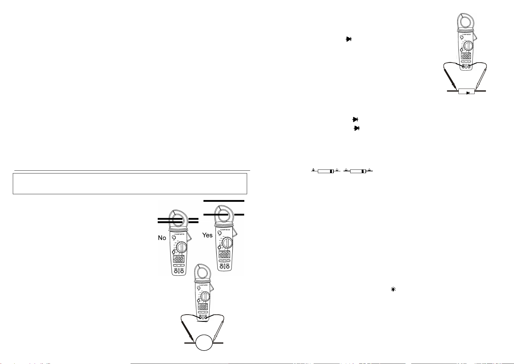
AC Current Measurements
WARNING: Ensure that the test leads are
disconnected from the meter before making current
clamp measurements.
1. Set the Function switch to the 400 or 200A or20A or
2A range. If the range of the measured is not known,
select the higher range first then move to the lower
range if necessary.
2. Press the trigger to open jaw. Fully enclose one conductor
to be measured.
3. The clamp meter LCD will display the reading.
AC/DC Voltage Measurements
1. Insert the black test lead into the negative COM terminal and the
red test lead into the positive Vterminal.
2. Set the function switch to the V position.
3. Select AC or DC with the MODE button.
4. Connect the test leads in parallel to the circuit under test.
5. Read the voltage measurement on the LCD display.
Resistance and Continuity Measurements
1. Insert the black test lead into the negative COM terminal and the
red test lead into the positive terminal.
2. Set the function switch to the •))) Ωposition.
3. Use the multifunction MODE button to select resistance.
4. Touch the test probe tips across the circuit or component under
test. It is best to disconnect one side of the device under test so
the rest of the circuit will not interfere with the resistance reading.
5. For Resistance tests, read the resistance on the LCD display.
6. For Continuity tests, if the resistance is < 120Ω, a tone will sound.
Diode Measurements
1. Insert the black test lead banana plug into the negative COM jack and the red test
lead banana plug into the positive diode jack.
2. Turn the rotary switch to the •))) position.
3. Press the MODE button until “ “ appears in the display.
4. Touch the test probes to the diode under test. Forward voltage will indicate 0.4V to
0.7V. Reverse voltage will indicate “OL”. Shorted devices will indicate near 0mV
and an open device will indicate “OL” in both polarities.
Data Hold
To freeze the LCD meter reading, press the data hold button. The data hold button is located
on the left side of the meter (top button). While data hold is active, the DH display icon appears
on the LCD. Press the data hold button again to return to normal operation.
MAX Hold
To hold the highest reading on the LCD, press the MAX hold button. The MAX hold button is
located on the left side of the meter (bottom button). The meter reading will not change as
readings change, rather it will only display the highest reading encountered since the MAX hold
button was pressed. Press the MAX hold button again to return to normal operation.
Manual Ranging
The meter turns on in the autoranging mode. Press the Range button to go to manual ranging.
Each press of the range button will step to the next range as indicated by the units and decimal
point location. Press and hold the Range button for two seconds to return to autoranging.
Manual ranging does not function in the AC Current, Diode and Continuity check functions
Backlight
The backlight function illuminates the display and is used when the ambient light to too low to
permit viewing of the displayed readings. Press the button for one second to turn the
backlight on and press the button a second time to turn the backlight off.
Battery Replacement
1. Remove the one rear Phillips head screw
2. Open the battery compartment
3. Replace the Requires two “AAA” batteries (UM4 R03)
4. Re-assemble the meter
Red Black Black Red
Probe Probe Probe Probe
Forward test Reverse test
V

Other Morris Products Measuring Instrument manuals

Morris Products 57276 User manual

Morris Products

Morris Products 57276 User manual

Morris Products 57085 User manual

Morris Products

Morris Products 57085 User manual

Morris Products 57262 Assembly instructions

Morris Products

Morris Products 57262 Assembly instructions

Morris Products 59116 User manual

Morris Products

Morris Products 59116 User manual

Morris Products 57200 User manual

Morris Products

Morris Products 57200 User manual

Popular Measuring Instrument manuals by other brands

Chauvin Arnoux DigiFlex MA4000D-350 user manual

Chauvin Arnoux

Chauvin Arnoux DigiFlex MA4000D-350 user manual

Sigicom INFRA Point manual

Sigicom

Sigicom INFRA Point manual

EXFO OmniCure R2000 user guide

EXFO

EXFO OmniCure R2000 user guide

SONOPAN DLM-102 instruction manual

SONOPAN

SONOPAN DLM-102 instruction manual

Omicron Lab CP AL1 user manual

Omicron Lab

Omicron Lab CP AL1 user manual

Gammon SC-B/2HB-2D-2 user guide

Gammon

Gammon SC-B/2HB-2D-2 user guide

EyeQue Personal Vision Tracker  EQ101 product manual

EyeQue

EyeQue Personal Vision Tracker EQ101 product manual

Samoa 680300 Parts and technical service guide

Samoa

Samoa 680300 Parts and technical service guide

REED TM-8811 instruction manual

REED

REED TM-8811 instruction manual

Agilent Technologies B2901 Guide

Agilent Technologies

Agilent Technologies B2901 Guide

Fox Thermal FT1 manual

Fox Thermal

Fox Thermal FT1 manual

CyberOptics SE500CP Hardware manual

CyberOptics

CyberOptics SE500CP Hardware manual

Stoneridge digifobpro user guide

Stoneridge

Stoneridge digifobpro user guide

TELEDYNE API T200U NOy Operator's manual

TELEDYNE API

TELEDYNE API T200U NOy Operator's manual

Inter-m LM-6228 Operation manual

Inter-m

Inter-m LM-6228 Operation manual

Hanna Instruments HI 95724C instruction manual

Hanna Instruments

Hanna Instruments HI 95724C instruction manual

Phonak Ear-Gauge user guide

Phonak

Phonak Ear-Gauge user guide

KRAL BEM 500 Series operating instructions

KRAL

KRAL BEM 500 Series operating instructions

manuals.online logo
manuals.online logoBrands
  • About & Mission
  • Contact us
  • Privacy Policy
  • Terms and Conditions

Copyright 2025 Manuals.Online. All Rights Reserved.