-Always set the select knob to the OFF position after use.
-For long time storage, the battery should be taken out to prevent from leaking of battery
liquid damaging the interior parts.
WARNING
Electrical circuits can be dangerous and /or lethal when lack of caution or poor safety
practices are used.
DESCRIPTION OF WARNING SYMBOLS
Earth (ground) TERMINAL
Equipment protected throughout by Double Insulation.
Caution, risk of electric shock
Caution (refer to accompanying document)
5. Operation
5.1 AC Current measurement
Make certain that all test leads are disconnected from instrument terminals.
a. Set the range selector switch to highest 400A range position.
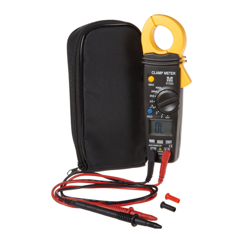
b. Press the trigger to open the transformer jaws and clamp on to one conductor only.
Take the current reading directly. It is recommended that the conductor be placed at the
center of the closed jaws for maximum accuracy.
c. When the reading is lower than 200A, set the range selector switch to the 200A range
position.
5.2 AC Voltage measurement
a. Set the range selector switch to the AC 600V range position. Insert the red test lead
into the V/Ω/ TEMP. terminal of the instrument and black test lead into COM terminal.
b. Connect the prod tips to the circuit under test and take the voltage reading directly.
5.3 DC Voltage measurement
a. Set the range selector switch to the DC 600V range position. Insert the red test lead
into the V/Ω/ TEMP. terminal of the instrument and black test lead into the COM
terminal.
b. Connect the prod tips to the circuit under test and take the voltage reading directly.
5.4 Resistance Measurement, Continuity and Diode check
Make certain that there is No voltage in the circuit or components being measured.
a. Set the range selector switch to the Ω position.
b. Insert the red test lead into the V/Ω/ TEMP. terminal of the instrument and the black
test lead into the COM terminal.
c. The display should indicate an over-range condition (display “1”) when the test leads
are open.
d. Connect the test leads to the circuit under test and take the resistance reading directly.
5.5 Continuity check
Make certain that there is No voltage in the circuit or components being measured.
a. Set the range selector switch to the.))) position.
b. Insert the red test lead into the V/Ω/ΤΕΜP. terminal of the instrument and the black
test lead into the COM terminal.
c. The display should indicate an over-range condition (display “1”) when the test leads
are open.
d. Connect the test leads to the circuit under test and take the resistance reading. When
the resistance measured reading is blow 30 Ω , the buzzer sounds, it is continuity
check.
5.6 Diode Measurement
Make certain that there is No voltage in the circuit or components being measured.
a. Set the range selector switch to the position.
b. Insert the red test lead into the V/Ω/ TEMP. terminal of the instrument and the black
test lead into the COM terminal.
c. The display should indicate an over-range condition (display “1”) when the test leads
are open.
d. Connect the red test lead to the anode of the diode to be measured and the black test
lead to the cathode.
e. The forward voltage drop in mV will be displayed. If the diode is reversed, the figure
“1” should be shown on the display.
5.7 Temperature measurement
a. Set the range selector switch to the temperature (℃or ℉) position.
b. Insert the red plug of “K” type thermoelectric coupling into the V/Ω/ TEMP. terminal
of the instrument and the black plug of “K” type thermoelectric coupling into the COM
terminal.
c. Connect the temperature probe to the point to be measured and take temperature
reading from the LCD display.
5.8 Data Hold Function
The reading will be hold when the Data Hold Button Switch is pressed. If the Button
Switch is pressed once again, will release the hold and allow a further measurement.
6. Battery Replacement
If the “BAT” symbol appears on the display, you should replace the battery.
a. Remove the test leads from the instrument and set the power switch to the OFF
position.
b. Unscrew the battery compartment cover.
c. Replace with a new 9V battery.


