Morris 57070 User manual

Model 57070
DIGITAL
MULTIMETER
INSTRUCTION MANUAL
SAFETY INFORMATION
To ensure safe operation, and in order to exploit to the full
the functionality of the meter, please follow the directions in
this section carefully.
WARNING
This multimeter has been designed according to IEC-1010 concerning
electronic measuring instruments with an overvoltage category CAT II
1000V, CAT III 600V and pollution 2.
Follow all safety and operating instructions to ensure that the meter is
used safely and is kept in good operating condition.
With proper use and care, the digital meter will give you years of
satisfactory service.
●PRELIMINARY
- When using the meter, the user must observe all normal safety
rules concerning:
Protection against the dangers of electrical current.
Protection of the meter against misuse.
- When the meter is delivered, check that it has not been damaged in
transit.
- Test leads must be in good condition. Before using verify that the
insulation on test leads are not damaged and/or the lead wires are
not exposed.
- Full compliance with safety standards can be guaranteed only if used
with test leads supplied. If necessary, they must be replaced with the
same model or same electric ratings.
●DURING USE
- Before using, you must select the right input jack, function and range.
- Never exceed the protection limit values indicated in specifications
for each range of measurement.
- 1 -

- When the value scale to be measured is unknown beforehand, set
the range selector at the highest position.
- Do not measure voltage if the voltage on the terminals exceeds
1000V above earth ground.
- Always be careful when working with voltages above 60V DC or 30V
AC rms, keep fingers behind the probe barriers while measuring.
- Before rotating the transform switch to change functions and ranges,
disconnect test leads from the circuit under test.
- Never perform resistance, transistor and diode measurements on live
circuits.
- Never use the meter under the condition of the explosive air, steam
or dirt.
- If any faults or abnormalities are observed, the meter cannot be used
any more and it has to be checked out.
- Never use the meter unless the rear case is in place and fastened
fully.
- Please do not store or use meter in areas exposed to direct sunlight,
high temperature, humidity or condensation.
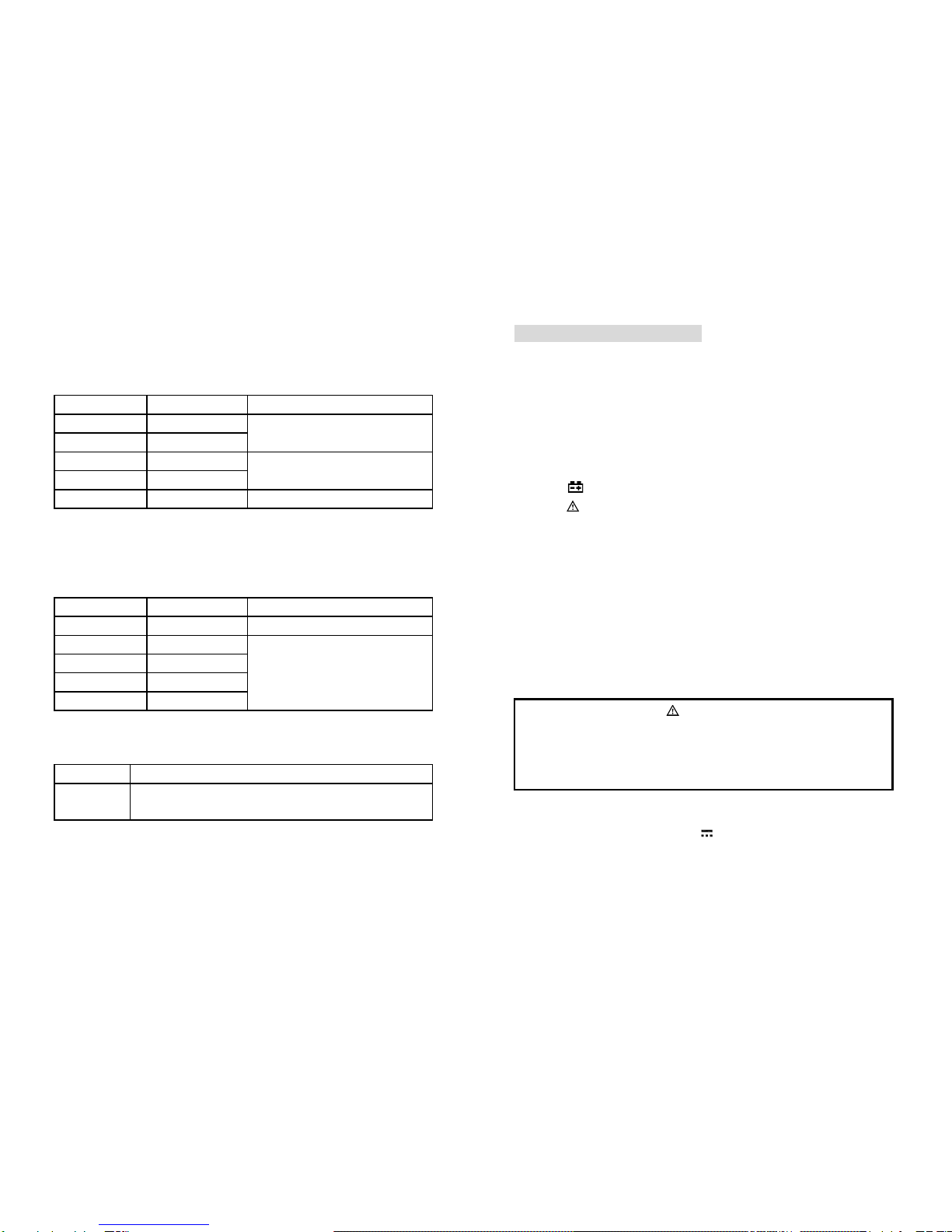
●SYMBOLS
Important safety information, refer to the operating manual.
Double insulation(Protection classΙΙ).
CAT ΙΙ Overvoltage (Installation) category II, Pollution Degree 2 per
IEC1010-1 refers to the level of Impulse Withstand Voltage
protection provided.
CAT ΙΙΙ Overvoltage (Installation) category III, Pollution Degree 2 per
IEC1010-1 refers to the level of Impulse Withstand Voltage
protection provided.
High voltage warning symbol
Conforms to european union directive
Earth ground
Fuse
- 2 -
~Alternating current
Direct current
Diode
H This indicates that the display data is being held.
The battery is not sufficient for proper operation.
●MAINTENANCE
-Please do not attempt to adjust or repair the meter by removing the
rear case while voltage is being applied. A technician who fully
understands the danger involved should only carry out such actions.
- Before opening the battery cover or case of the meter, always
disconnect test leads from all tested circuits.
- To avoid the misreadings, when the meter displays“ ”, you must
change the battery.
- For continued protection against fire, replace fuse only with the
specified voltage and current ratings: F 200mA/250V (quick acting).
- Do not use abrasives or solvents on the meter; use a damp cloth and
mild detergent only.
- Always set the power switch to the OFF position when the meter is
not in use.
- If the meter is to be stored for a long period of time, the batteries
should be removed to prevent damage to the unit.
DESCRIPTION
- This meter is a portable professional measuring instrument with a
handsome LCD for easy reading.
- Single operation of the transform switch makes measurement
convenient. Overload protection and low battery indication are
provided. This meter is ideal for use in the fields, workshop, school,
hobby and home applications.
- This meter includes the data hold function.
- 3 -

●NAMES OF COMPONENTS
⑴LCD Display
⑵Panel
⑶H Button: This Button is used
to the switch of data hold.
⑷Transform Switch:
This switch is used to select
functions and desired ranges.
⑸10AJack: Input terminal for
current 0 ~ 10A.
⑹COM Jack: Common terminal
for measurement.
⑺hFE Jack: This Jack is used
for transistor test.
⑻V/Ω/mA Jack: Input Jack
SPECIFICATIONS
Accuracy is specified for a period
of 1 year after calibration and at
18℃to 28℃(64°F to 82°F)
with relative humidity to 75%.
●GENERAL SPECIFICATIONS
- Max. Voltage Between Terminals And Earth Ground: 1000V DC or
750V AC
- Fuse Protection: F 200mA/250V (quick acting).
- Display: 15mm LCD
- Max. Show Value: 1999 (3-1/2)
- Polarity Indication: ‘-’indicates negative polarity.
- Overrange Indication: Display ‘1’
- Sampling Time: approx. 0.4 second
- Low Battery Indication: ‘ ’ displayed
- 4 -
- Power Supply: 1.5V×3 AAA battery.
- Operating Temperature: 0℃to 40℃(32°F to 104°F)
- Storage Temperature: -10℃to 50℃(10°F to 122°F)
- Dimension & Weight: 158×74×32 mm, 250g(including battery)
●ELECTRICAL SPECIFICATIONS
Circumstance Temperature: 23℃±5℃, Relative Humidity: < 75%
DC Voltage
Range Resolution Accuracy
200mV 0.1mV ±(0.5% of rdg + 2 digits)
2V
0.001V
±(0.5% of rdg + 3 digits)
20V 0.01V ±
(
0.8% of rdg + 3 digits
)
200V 0.1V
1000V 1V ±(0.8% of rdg + 5 digits)
- Input Impedance: 1MΩ
- Overload Protection: 200mV range: 250V DC or AC rms, 2V-1000V
ranges: 1000V DC or 750VAC rms.
- Max. Input Voltage: 1000V DC
AC Voltage
Range Resolution Accuracy
200V 0.1V ±(1.2% of rdg + 10 digits)
750V 1V
- Input Impedance: 1MΩ
- Overload Protection: 750V AC rms or 1000V DC
- Frequency Range: 40 to 400Hz
- Response:Average, calibrated in rms of sine wave.
- Max. Input Voltage: 750V rms AC
Diode
Range Resolution Function
0.001V Display: read approximate forward
voltage of diode
- 5 -

- Forward DC Current: approx. 1mA
- Reversed DC Voltage: approx.2.8V
- Overload Protection: 250V DC or rmsAC
DC Current
Range Resolution Accuracy
200μA 0.1μA ±(1.0% of rdg + 2 digits)
2mA
0.001mA
20mA 0.01mA ±(1.5% of rdg + 2 digits)
200mA 0.1mA
10A 0.01A ±(3.0% of rdg + 2 digits)
- Overload Protection: μA, mA ranges: F 200mA/250V fuse (quick
acting), 10Arange: unfused.
- Max. Input Current: mAJack: 200mA, 10A Jack: 10A
- voltage drop: 200mV
Resistance
Range Resolution Accuracy
200Ω0.1Ω±(1.0% of rdg + 3 digits)
2kΩ0.001kΩ
20kΩ0.01kΩ±(1.0% of rdg + 2 digits)
200kΩ0.1kΩ
2MΩ0.001MΩ
- Open Circuit Voltage: 2.8V
- Overload Protection: 250V DC or rms AC
Transistor hFE
Range
Function
hFE Display: read approximate hFE value (0-
1000) of
transistor under test (ALL TYPE)
- Base Current: approx. 2µA,Vce: approx. 2.8V
- 6 -
OPERATING INSTRUCTION
●DATA HOLD
If you need data hold when measuring, you can press on “H” button, it
will hold the reading; if you press the button again, data hold will not
continue.
●PREPARATION FOR MEASUREMENT
- Turn on the meter. If the battery voltage is less than 3.6V, display will
show “ ”, the battery should be changed at this time.
- The “
- Select a function and a range for the item to be measured by rotating
the transform switch to the selected position. When the value scale
to be measured is unknown beforehand, set the range selector at the
highest position.
” besides the input jack shows that the input voltage or
current should be less than specification on the sticker of the meter
to protect the inner circuit from damaging.
- When connecting, first connect to the public testing line, then to the
electriferous testing line. When you remove it, you should remove
the elecriferous one first.
●MEASURING DC VOLTAGE
You can’t test voltage which more than 1000V DC, it’s possible
to show higher voltage, but it may destroy the inner circuit.
WARNING
Pay attention not to get an electric shock when measuring
high voltage.
- Connect the black test lead to the COM jack and the red test lead to
the V jack.
- Set the transform switch at the V range position.
- Connect test leads across the source or load under measurement.
- You can get a reading from LCD display. The polarity of the red test
lead connection will be indicated. - 7 -

NOTE:
- When only the figure ‘1’ is displayed, it indicates overrange situation
and the higher range has to be selected.
- When the value scale to be measured is unknown beforehand, set
the range selector at the highest position.
●MEASURING AC VOLTAGE
- Connect the black test lead to the COM jack and the red test lead to
the Vjack.
- Set the transform switch at the V range position.
- Connect test leads across the source or load under measurement.
- You can get reading from LCD.
You can’t input a voltage which is more than 750V rms AC, it’s
possible to show higher voltage, but it’s may destroy the inner
circuit.
WARNING
Pay attention not to get an electric shock when measuring
voltage.
NOTE:
- When only the figure ‘1’ is displayed, it indicates over range situation
and the higher range has to be selected.
- When the value scale to be measured is unknown beforehand, set
the range selector at the highest position.
●MEASURING DC CURRENT
Shut down the power of the tested circuit, then connect the
meter with the circuit for measurement.
WARNING
- Connect the black test lead to the COM jack and the red test lead to
the mA jack for a maximum of 200mA current. For a maximum of
10A, move the red lead to the 10A jack.
- Set the transform switch at the A range position.
- 8 -
- Connect test leads in series with the load under measurement.
- You can get reading from LCD. The polarity of red test lead will be
indicated.
NOTE:
- When only the figure ‘OL’ is displayed, it indicates over range
situation and the higher range has to be selected.
- When the value scale to be measured is unknown beforehand, set
the range selector at the highest position.
- “
” means the socket of INPUT maximum current is 200mA, over
current will destroy the fuse. 10A’s maximum current is 10A, no fuse
protection.
●MEASURING RESISTANCE
When measuring in-circuit resistance, be sure the circuit under
test has all power removed and that all capacitors have been
discharged fully.
WARNING
- Connect the black test lead to the COM jack and the red test lead to
the Ωjack.
- Set the transform switch at the Ωrange position.
- Connect test leads across the resistance under measurement.
- You can get reading from LCD.
NOTE:
- When only the figure ‘1’ is displayed, it indicates over range situation
and the higher range has to be selected.
- When the input is not connected, i.e. at open circuit, the figure ‘1’ will
be displayed for the over range condition.
●TESTING DIODE
- Connect the black test lead to the COM jack and the red test lead to
the Ωjack. (The polarity of red lead is “+”)
- Set the transform switch at the range position.
- 9 -

- Connect the red lead to the anode, the black lead to the cathode of
the diode under testing.
- You can get reading from LCD.
NOTE:
- The meter will show the approximate forward voltage drop of the
diode.
- If the lead connection is reversed, only figure ‘1’ will be displayed.
- When the input is not connected, i.e. at open circuit, the figure ‘1’ will
be displayed.
•TESTING TRANSISTOR
- Set the transform switch at the hFE range position.
- Identify whether the transistor is NPN or PNP type and insert emitter,
base and collector leads into the proper holes of the transistor on the
socket for testing.
- You can get reading from LCD.
MAINTENANCE
●BATTERY REPLACEMENT
Before attempting to open the battery cover of the meter, be
sure that test leads have been disconnected from
measurement circuit to avoid electric shock hazard.
WARNING
- Loosen the screw fixing the battery cover and remove it.
- Replace the exhausted battery with a new one.
- Replace the battery cover.
●FUSE REPLACEMENT
- Loosen the screw fixing the battery cover and remove it.
- Replace the blown fuse with ratings specified.
- 10 -
- Replace the battery cover.
Before attempting open the battery cover of the meter, be sure
that test leads have been disconne
cted from measurement
circuit to avoid electric shock hazard.
WARNING
For protection against fire, replace fuses only with specified
ratings: F 200mA/250V (quick acting).
●TEST LEADS REPLACEMENT
Full compliance with safety standards can be guaranteed only
if used with the test leads supplied. If necessary, they must be
replaced with the same model or same electric ratings. Electric
ratings of the test leads: 1000V 10A.
WARNING
You must replace the test leads if the lead is exposed.
ACCESSORIES
⑴Test Leads: Electric Ratings 1000V 10A one piece
⑵Battery:1.5V, AAA three pieces
⑶
Instruction Manual one piece
- 11 -
Table of contents
Other Morris Multimeter manuals