INTRODUCTION
Morso Jernstoberi A/S retained OMNI to perform U.S. Environmental Protection Agency (EPA)
third party certification on the 6100 B frestanding room heater. The 6100 B is a cast iron
freestanding wood burning room heater. The firebox is constructed of cast iron. Usable firebox
volume was measured to be 0.5050 cubic feet and the stove is vented through 6” flue collar
located on the stove top.
Testing was performed at Danish Technological Institute (DTI) located at Kongsvangalle 29,
DK-8000 Aarhus C, Denmark. Report number 300-ELAB-2381-EPA dated August 27, 2019
was generated by DTI and submitted to OMNI for review and third-party certification.
This report is organized in accordance with the EPA-recommended outline and is summarized in
the Table of Contents immediately preceding this section. The results in this report are limited to
the item submitted.
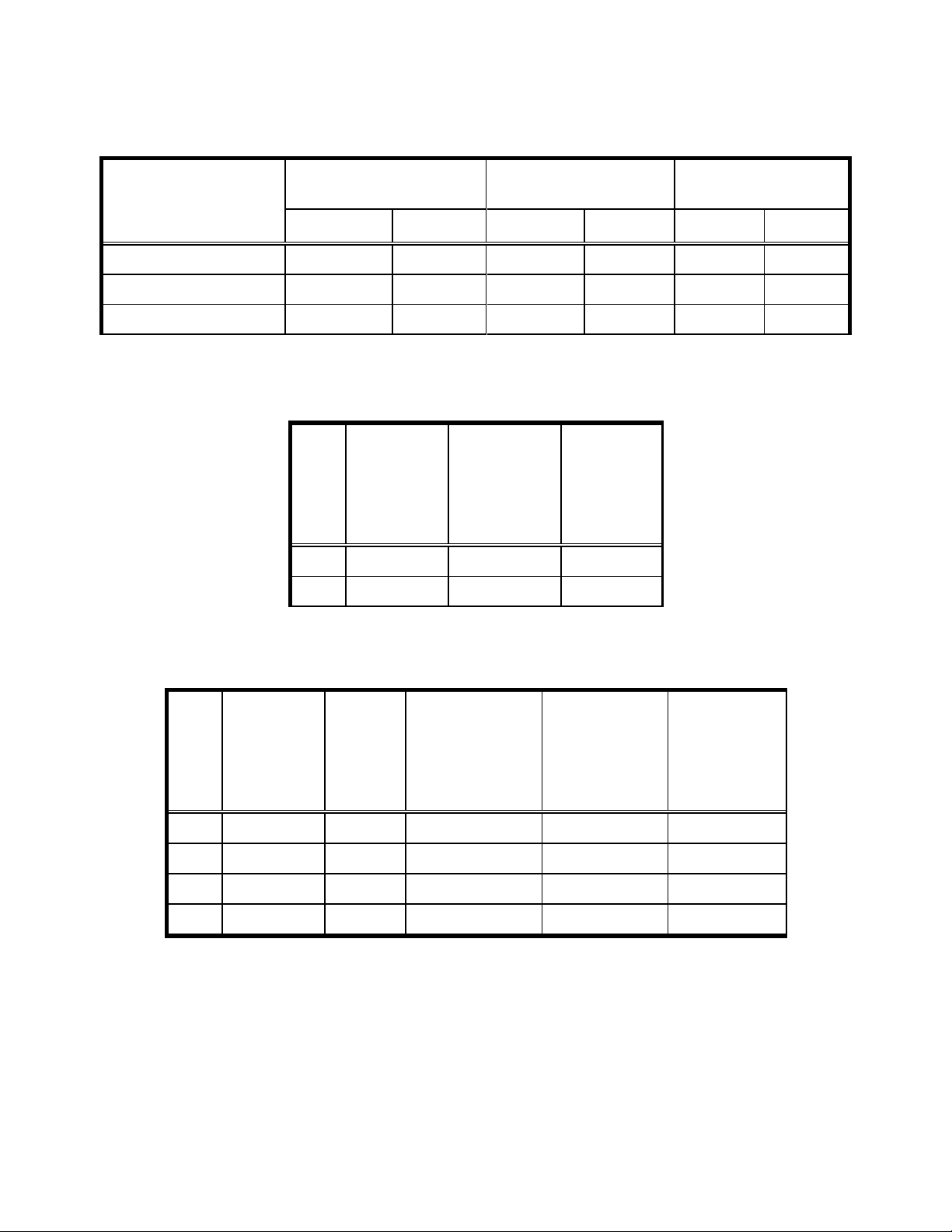
SAMPLING PROCEDURE
The 6100 B was tested in accordance with the U.S. EPA 40 CFR Part 60, Subpart AAA –
Standards of Performance for New Residential Wood Heaters using EPA ASTM E2515 and
E3053 per EPA Alt-125’s requirements for cordwood testing in accordance with the CFR. No
28R. Particulate emissions were measured using sampling trains consisting of two Teflon coated
47mm filters (front and back).
The model 6100 B was tested for thermal efficiency and carbon monoxide (CO) emissions in
accordance with CSA B415.1-10 using Birch cordwood.
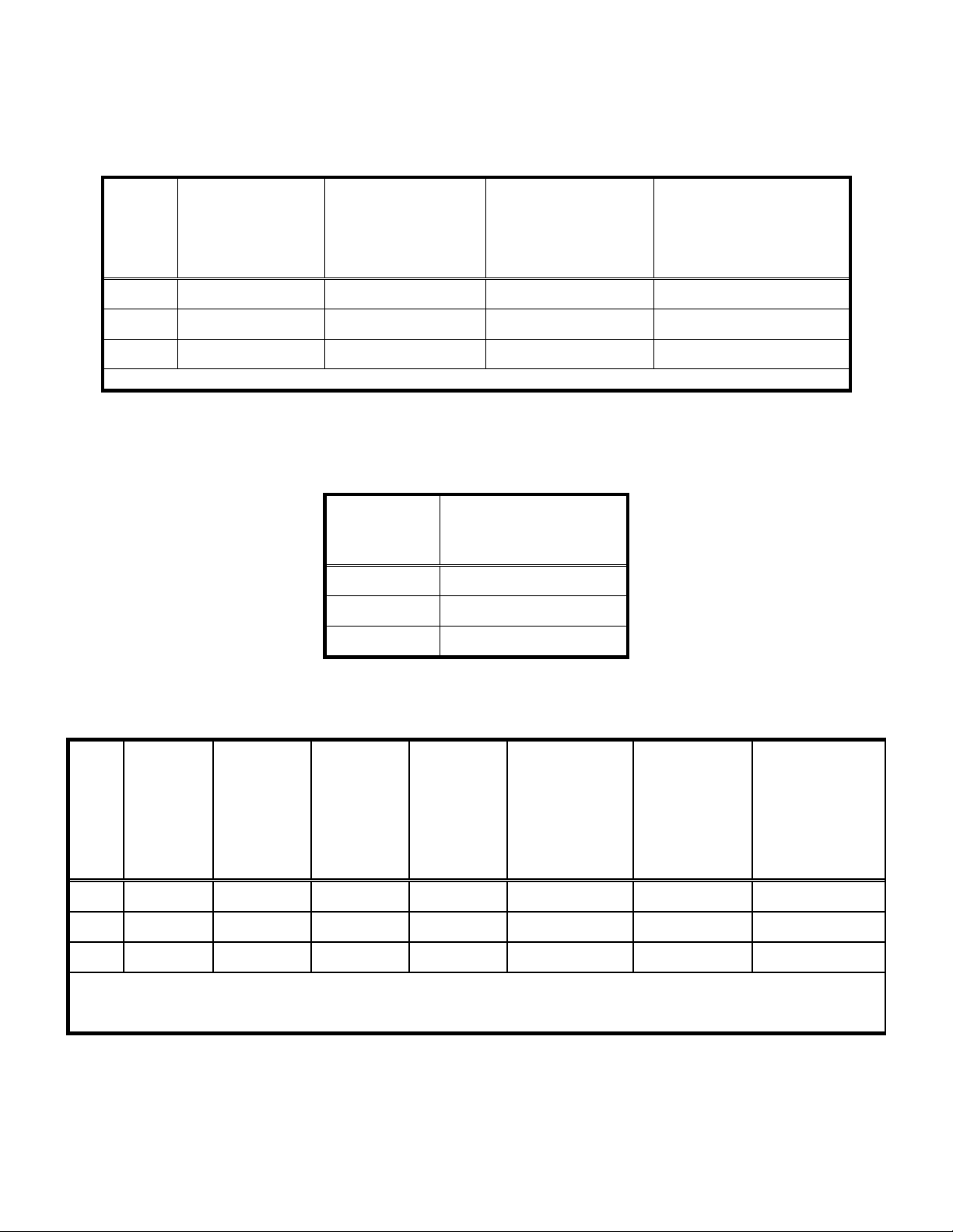
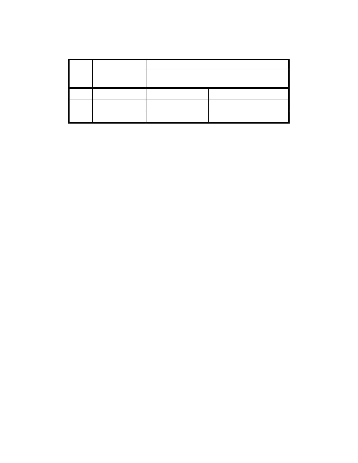
SUMMARY OF RESULTS
The weighted average emissions of the four test runs included in the results indicate a particulate
emission rate of 0.67 grams per hour. Particulate emissions were sampled on one of the high
burn fuel loads. The 6100 B results are within the emission limit of 2.5 g/hr for affected
facilities tested with cordwood, manufactured on or after May 15, 2020.
The proportionality results for all 3 test runs were acceptable when calculated at a 10-minute
sample rate. Quality check results for each test run are presented in Section 2 of this report.