morse 456-CE Series User manual

Copyright 2019 - Morse Mfg. Co., Inc. Form PL456-CE (278575-______) (Updated 17 Oct, 2019) 1
The Specialist In Drum Handling Equipment
Model 456-1-50-CE & 456-3-50-CE
CE-Marked Hydra-Lift Drum Rollers
Syracuse, NY, 13208 U.S.A.
morsedrum.com (315) 437-8475
CONTENTS
Page
Receiving Procedures. . . . . . . . . . . . . . . . . . . . 1
Warranty. . . . . . . . . . . . . . . . . . . . . . . . . . . . . 1
Safety Information. . . . . . . . . . . . . . . . . . . . . 1 - 2
Machine Description. . . . . . . . . . . . . . . . . . . 3
Options. . . . . . . . . . . . . . . . . . . . . . . . . 3
Installation Instructions. . . . . . . . . . . . . . . . . 4 - 5
Operating Instructions. . . . . . . . . . . . . . . 5 - 6
Maintenance. . . . . . . . . . . . . . . . . . . . . . . . 6
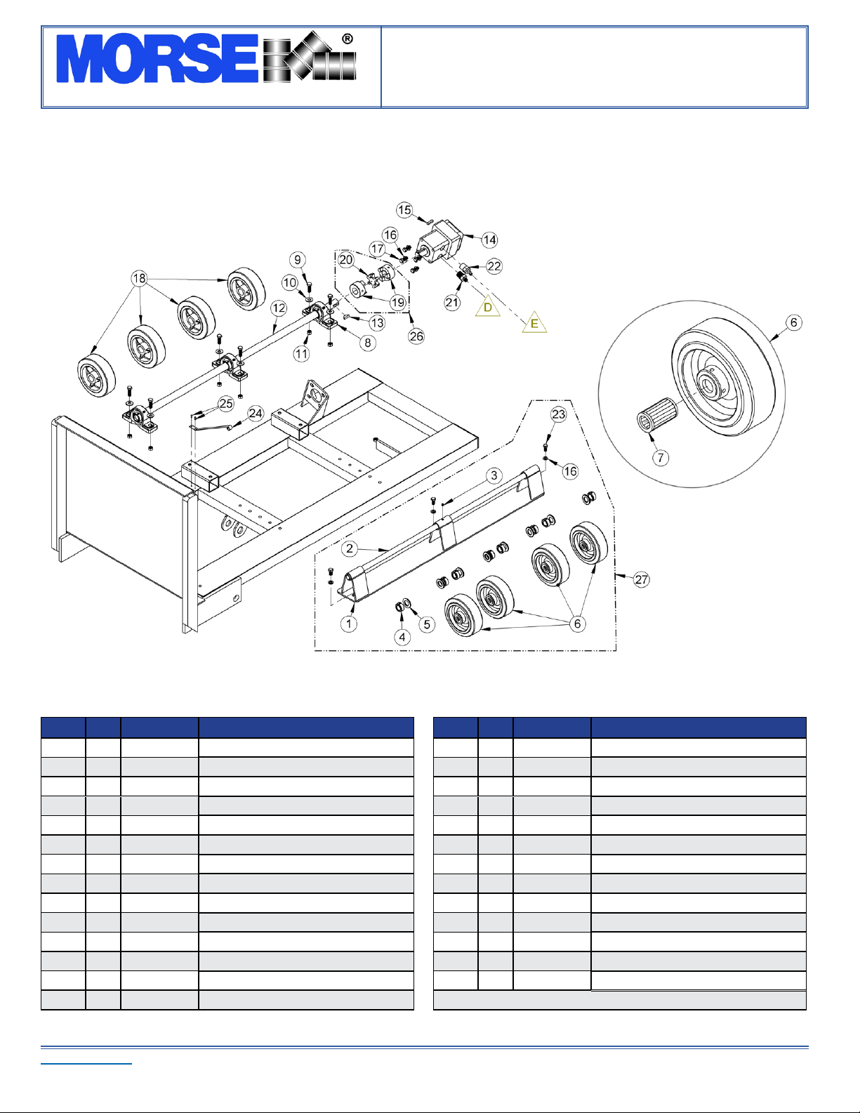
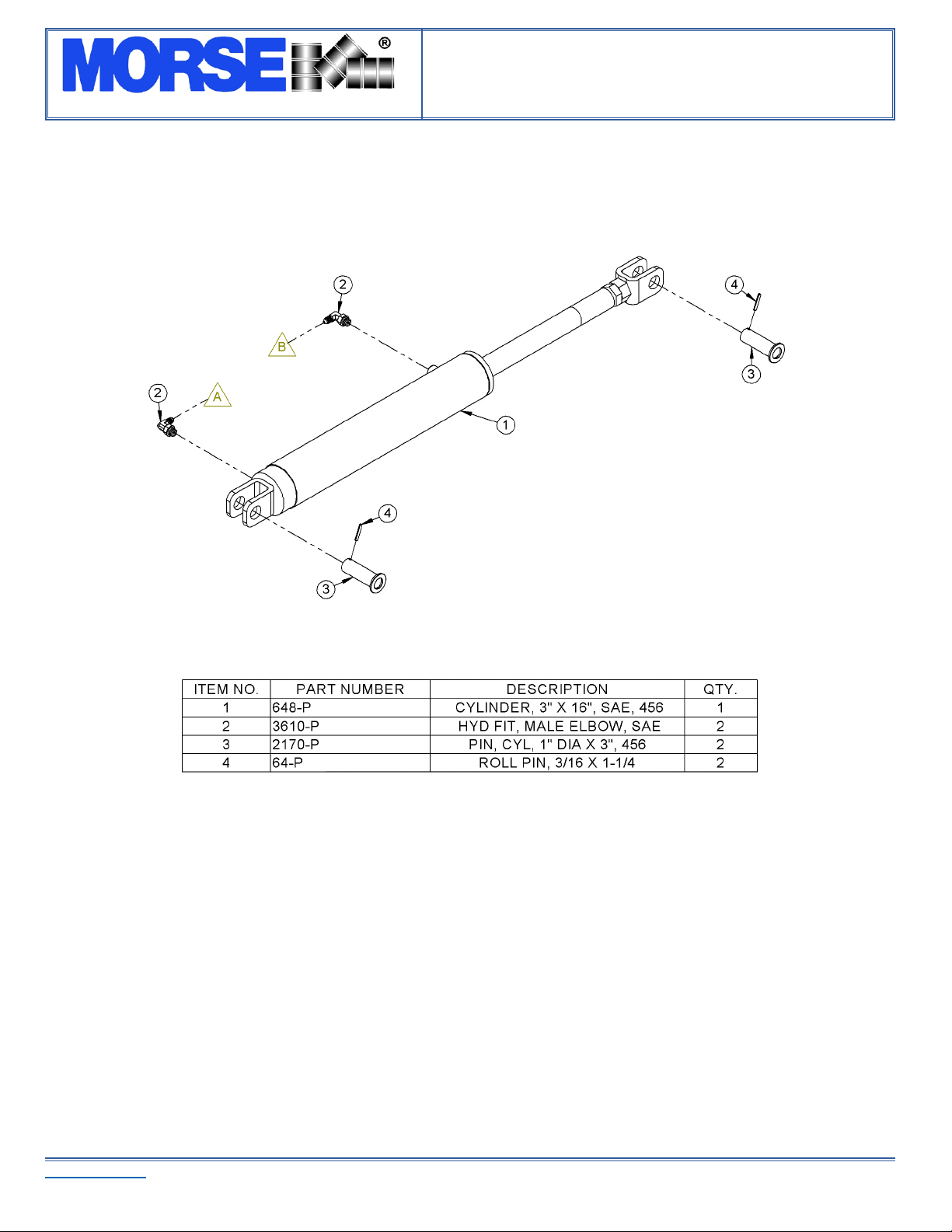
Parts Lists and Diagrams. . . . . . . . . . . . . . 7 - 11
Specications. . . . . . . . . . . . . . . . . . . . . . . . 12
Declaration of Conformity. . . . . . . . . . . . . . . . 13
Operator’s Manual
for Morse
CE-Marked Hydra-Lift Drum Rollers
456-CE Series
Serial Number 278575 to ______
Receiving Procedures
Every Morse drum handler is inspected prior to shipping. However, damage
may be incurred during transit.
Check for visible damage. If you choose to accept damaged freight,•
always sign noting the damage on the Bill of Lading.
Document the damage and have the truck driver sign. We•
recommend keeping a digital camera at your receiving dock for this
purpose.
Open packages expeditiously to check the condition of the•
goods. There is only a 24 hour window to notify the carrier of any
concealed damage.
Immediately• report all damage to the shipping company! Then
you may contact Morse for assistance with your freight claim.
Morse Manufacturing will not be held responsible for any damaged•
freight that is not signed for as damaged.
Limited 2 Year Warranty
Morse drum handling equipment is guaranteed against defects in
workmanship or materials for two years when used properly within its rated
capacity. Warranty does not cover wear from normal use or damage from
accident or abuse. Motors and other purchased parts carry the warranties
of their manufacturers.
For warranty claims, contact your Morse Dealer to obtain a
return authorization number, and for return freight advice. Return freight
must be prepaid.
In all instances, liability is limited to the purchase price paid or to
repairing or replacing the product. Customer assumes liability for any
modications, unauthorized repairs or parts substitution.
Safety Information
While Morse Manufacturing Co. drum handling equipment is engineered for
safety and eciency, a high degree of responsibility must be placed upon
the machine operator to follow safe practices, based primarily on common
sense, upon which true safety depends.
Failure to follow the safety precautions in this manual can result in personal
injury or property damage. Observe the same precautions as with similar
machinery where carelessness in operating or maintenance is hazardous
to personnel. Carefully read the safety precautions below and throughout
this manual.
Review the Material Safety Data Sheet(s) for the material(s) in the drum(s)
and take all necessary precautions. Safety shoes, work gloves, hard hat
and other personal protective devices are recommended.
Prior to initial use, inspect all moving parts and test rotation of wheels.
Perform necessary inspections, operator training, etc.

The Specialist In Drum Handling Equipment
Model 456-1-50-CE & 456-3-50-CE
CE-Marked Hydra-Lift Drum Rollers
Operator’s Manual for Morse 456-CE Series CE-Marked Hydra-Lift Drum Rollers
Serial Number 278575 to ______
morsedrum.com
Copyright 2019 - Morse Mfg. Co., Inc. Form PL456-CE (278575-______) (Updated 17 Oct, 2019) 2
Safety Information (continued)
DANGER - Indicates a situation which, if not avoided, will result in serious injury or death.
This signal word is limited to the most extreme situations.
WARNING - Indicates a situation which, if not avoided, could result in serious injury or
death.
CAUTION - Indicates a situation which, if not avoided, can result in damage to the machine.
DANGER - Watch Out for Pinch Points. Stay clear of moving parts. Do Not Stand Near any Part of a Rotating Drum
or Drum Holder. Operator should remain directly in front of the control station while operating the rotator. Morse CE-
Marked Drum Rotators comply with OSHA subpart O, 1910.212 - “General requirements for all machines.” “Revolving
drums, barrels, and containers shall be guarded by an enclosure which is interlocked with the drive mechanism, so that
the barrel, drum, or container cannot revolve unless the guard enclosure is in place.” (A safety enclosure is included
with each CE-Marked MORSE drum rotator.)
WARNING - The 456-CE Series is designed to handle one drum of the types listed at the top of page 3 under machine
description. DO NOT attempt to handle any other type of drum or object. DO NOT exceed the weight capacity.
WARNING - Level Floors Only. For operation only on clean, level oors of suitable bearing capacity. Do not use on
sloped surfaces, ramps, irregular or debris strewn oors.
WARNING - Properly Mount to Floor. Do Not put into service without proper oor mounting and leveling. Use the four
mounting holes in each corner of the base to anchor to oor.
WARNING - Do Not Modify the Unit. Under no circumstances should any modications be made to the Morse
machinery without factory authorization. Any modications may void the warranty. This machine was designed to
perform a specic job and alterations may result in injury to operator or machine.
WARNING - No Loose Fitting Clothing. Wear close-tting clothing and safety equipment appropriate to the job. Loose
tting clothing may become caught on the machinery and cause severe personal injury.
WARNING - Hydraulic Fluid Under Pressure Can Be Hazardous. Escaping hydraulic uid under pressure can penetrate
the skin, causing serious injury. Avoid the hazard by relieving pressure before disconnecting hydraulic lines. Keep
hands and body away from pinholes and nozzles which eject uid under high pressure. Use a piece of cardboard to
search for leaks. If an accident occurs, see a doctor immediately and inform them of the nature of the accident.
CAUTION - Wear safety shoes with non-slip soles and hard toe protection.
CAUTION: DO NOT allow drum to impact on oor.
WARNING: This product can expose you to chemicals including barium sulfate, cobalt, titanium dioxide, and
2-methylimidazole, which are known to the State of California to cause cancer, and bisphenol-A, which is known to
the State of California to cause birth defects or other reproductive harm.
For more information go to www.P65Warnings.ca.gov

The Specialist In Drum Handling Equipment
Model 456-1-50-CE & 456-3-50-CE
CE-Marked Hydra-Lift Drum Rollers
Operator’s Manual for Morse 456-CE Series CE-Marked Hydra-Lift Drum Rollers
Serial Number 278575 to ______
morsedrum.com
Copyright 2019 - Morse Mfg. Co., Inc. Form PL456-CE (278575-______) (Updated 17 Oct, 2019) 3
Machine Description
The Morse 456-CE Series CE-Marked Hydra-Lift Drum Rollers are designed to receive an
upright drum at oor level, hydraulically tilt drum to horizontal, and rotate the drum on its
side between 4 to 16 RPM. It is designed to rotate a steel drum 15.2 to 71.1 cm (6” to 28”)
in diameter, and up to 101.6 cm (40”) tall. The maximum liquid capacity is 454 kg (1000 Lb.).
Capacity is derated to 181 kg (400 Lb.) for a dry load.
Options
A 1 to 5 gallon can or pail can be rotated with the optional Idler Attachment (part # 1-5-1) installed.•
A 208 liter (55-gallon) plastic drum can be rotated with the correct POLY option installed.•
Order Option POLY-456 factory installed on your new 456-CE Series Drum Roller.•
Order Option POLY-456FI for eld installation of POLY Kit on your existing 456-CE Series Drum Roller.•
Controls
There are two powered functions for
the operator to control. Each function is
controlled separately by levers mounted
on the control station.
The “TILT” function, for vertical1.
positioning of the drum holder. The
lever on the right side is the “TILT”
control valve. Raising the lever will
tilt the drum to vertical. Lowering the
lever will tilt the drum to horizontal.
The “ROLL” function, or the rotation2.
of the drum holder. The lever on the
left side is the “ROLL” control valve.
Raising this lever causes the drum
to rotate. Lowering the lever away
from the operator will stop the drum
from rotating. The rotation speed can
be varied with the metering valve
(item 13 on page 9). Turn the valve
clockwise to increase speed up to a
nominal 16 RPM, counterclockwise
to decrease speed down to a nominal
4 RPM. RPM is based on a 57.2 cm
(22.5”) diameter 208 liter (55-gallon)
steel drum and a 50Hz 1425 RPM
motor.
Machine Unpacking
Carefully remove the top and sides of the crate covering the
machine so as not to damage painted surfaces, electrical
or hydraulic components. Inspect the machine for visible
damage. If damage is noted, follow receiving procedure on
page 1. Remove the (4) lag screws connecting the machine
base to the pallet. Remove machine from pallet by lifting
around the tilt bed assembly. Attach a strap to an overhead
crane and raise slowly, as the machine will have a tendancy
to tilt (see gure 1).
Control Station
Lockable Main
Disconnect
Start Button
Stop Button
Timer
Emergency Stop
TILT Control
ROLL Control
RPM Control
Figure 1

The Specialist In Drum Handling Equipment
Model 456-1-50-CE & 456-3-50-CE
CE-Marked Hydra-Lift Drum Rollers
Operator’s Manual for Morse 456-CE Series CE-Marked Hydra-Lift Drum Rollers
Serial Number 278575 to ______
morsedrum.com
Copyright 2019 - Morse Mfg. Co., Inc. Form PL456-CE (278575-______) (Updated 17 Oct, 2019) 4
Adjust drive and idler wheels to your particular drum.•
With provided 1/8” allen wrench, loosen
the two set screws found in each drive
wheel hub and the set screw in each
collar surrounding the idler wheels.
Wheels should be positioned to support
the drum at its strongest point; adjacent
to ribs (see Figure 1). This confguration
will also prevent the drum from moving
axially. Tighten set screws.
A variety of drum diameters can be
accommodated by adjusting the idler
plate assembly toward the drive side
for smaller diameters and away from
the drive side for larger diameters.
The plate may be adjusted to allow
drive shaft spacing from 8” to 18”. It
is preset to the second (outer) set of
holes for use with standard 55-gallon
steel drums. To adjust, remove the
three idler plate bolts (item 23 on page
8) and slide the idler plate assembly
(item 27 on page 8) to the proper set
of mount holes and refasten the mount
bolts.
Installation Instuctions
Hydra-Lift Rotators are shipped lled with hydraulic uid (Dexron 3 or equivalent). Replace the • RED shipping plug from the hydraulic
reservoir with the supplied BLACK breather, and install hydraulic levers BEFORE operation.
The base has four 1/2” (1.27 cm) diameter holes spaced 20-3/8” wide x 62-5/8” long (51.75 cm wide x 159.07 cm long). Morse•
recommends the rotator be secured to the oor using 3/8” x 3” (.95 cm x 7.6 cm) lag bolts (not included).
Install all Morse Rotators in accordance with OSHA requirements for enclosure and safety interlock, etc. Drum rotator must•
automatically turn o when enclosure door is opened.
Control Station - Making Connections:•
Figure 1
AIR Powered Models
For the air motor powered rotator, a lter, regulator, •
lubricator is mounted on the control station. A shuto
ball valve is installed on the inlet of the regulator. The air
connection should be made at the inlet of this valve.
Ensure that the supply air lines are of sucient size •
to provide proper air volume. The air motor requires
40 scfm, and 40 psi of compressed air. The proper air
pressure will depend on the weight of the drum (see Air
Motor Technical Info).
AC Powered Models
The main power must be wired into the control box.•
Models ordered with non-explosion proof motor and•
appropriate Morse Control Package have the control box
wired to the motor.
Models ordered with explosion proof motor and•
appropriate Morse Explosion-Proof Control Package have
no wiring from the nema 7/9 control box to the motor.
Please consult an electrician to complete the wiring.
Jog the motor to check rotation. Motor fan must turn•
clockwise.
To reverse rotation if necessary•
For 3 phase motors: interchange any two input leads.•
For 1 phase motors: interchange wires 5 & 8 in•
junction box.

The Specialist In Drum Handling Equipment
Model 456-1-50-CE & 456-3-50-CE
CE-Marked Hydra-Lift Drum Rollers
Operator’s Manual for Morse 456-CE Series CE-Marked Hydra-Lift Drum Rollers
Serial Number 278575 to ______
morsedrum.com
Copyright 2019 - Morse Mfg. Co., Inc. Form PL456-CE (278575-______) (Updated 17 Oct, 2019) 5
Loading a Drum
1. Raise the “TILT” lever to tilt the load plate
to oor level.
2. Place an upright drum onto the load
plate with a drum truck or with your crane
and a below-hook drum lifter.
3. Lower the “TILT” lever to tilt the drum
from upright into horizontal position.

The Specialist In Drum Handling Equipment
Model 456-1-50-CE & 456-3-50-CE
CE-Marked Hydra-Lift Drum Rollers
Operator’s Manual for Morse 456-CE Series CE-Marked Hydra-Lift Drum Rollers
Serial Number 278575 to ______
morsedrum.com
Copyright 2019 - Morse Mfg. Co., Inc. Form PL456-CE (278575-______) (Updated 17 Oct, 2019) 6
Rotating a Drum
4. After ensuring that the area around the rotator is
clear, raise the “ROLL” lever to begin rotation.
5. The drum rotation speed can be varied with the
metering valve (item 13 on page 9). Turn the valve
clockwise to increase speed up to 16 RPM, counter-
clockwise to decrease speed down to 4 RPM.
Unloading a Drum
Ensure the drum is in vertical upright position to unload. Unload upright drum from the load
plate with a drum truck or with your crane and a below-hook drum lifter.
Maintenance
Periodic inspection for the general condition of structural and mechanical components is
imperative for safe and ecient operation.
Idler wheels and drive bearings are equipped with grease tting and should be 1.
lubricated periodically. High pressure grease guns are not recommended, as their
force may damage seals.
Motors have permanently lubricated ball bearings.2.
Inspect the hydraulic system for oil drips, hose damage, or other signs of wear.3.
Inspect the level and condition of the hydraulic uid. Hydraulic uid level should be
within a ½” of the top of the reservoir when the cylinder is in the relaxed position.
Replace any parts that show signs of wear.
Lubricate all moving parts including: bearings and clevis pins.4.
Periodically inspect all moving parts, framework, contact areas, and oor mounting 5.
fasteners for signs of wear, fatigue, or loosening. Tighten, adjust or replace parts as
necessary to prevent failure and maintain proper function.

The Specialist In Drum Handling Equipment
Model 456-1-50-CE & 456-3-50-CE
CE-Marked Hydra-Lift Drum Rollers
Operator’s Manual for Morse 456-CE Series CE-Marked Hydra-Lift Drum Rollers
Serial Number 278575 to ______
morsedrum.com
Copyright 2019 - Morse Mfg. Co., Inc. Form PL456-CE (278575-______) (Updated 17 Oct, 2019) 7

The Specialist In Drum Handling Equipment
Model 456-1-50-CE & 456-3-50-CE
CE-Marked Hydra-Lift Drum Rollers
Operator’s Manual for Morse 456-CE Series CE-Marked Hydra-Lift Drum Rollers
Serial Number 278575 to ______
morsedrum.com
Copyright 2019 - Morse Mfg. Co., Inc. Form PL456-CE (278575-______) (Updated 17 Oct, 2019) 8
ITEM QTY. PART # DESCRIPTION
1 1 295-P IDLER PLATE WELD, 5154
2 1 301-P IDLER SHAFT, 3/4” X 38” 5154
3 1 1000-P SET SCREW, 1/4 - 20 x 1/4
4 8 15-P COLLAR, 3/4” ID
5 8 55-P WASHER, 3/4 SAE FL 1-1/2 OD
6 * 4 292-P WHEEL, IDLER, 6” W/ 3/4” BRG
7 4 1875-P BEARING, 3/4” ID, 6” WHEEL
8 3 297-P BEARING, 1” PILLOW BLOCK
9 6 535-P HHCS, 3/8-16 X 1-1/4 GR5
10 6 1166-P WASHER, 3/8 USS 1” OD
11 6 1169-P NUT, 3/8-16 REV HEX LOCK
12 1 299-P DRIVE SHAFT, 1” X 40” 5154
13 1 736-P KEY, WOODRUFF, SIZE 15, ASA808
14 1 351-P MOTOR, HYDRAULIC HYD, 400, 456
ITEM QTY. PART # DESCRIPTION
15 1 2656-P KEY, SQUARE, 1/4 X 1”
16 7 1474-P WASHER, 3/8 SPLIT LOCK
17 4 1572-P HHCS, 3/8-16 X 1 GR2
18 * 4 291-P WHEEL, DRIVE, 6” , 1” BORE
19 2 1665-P COUPLING BODY HALF, 1” BORE
20 * 1 305-P SPIDER, BUNA N, 5154
21 1 2120-P HYD FIT, MALE CONNECTOR, 400
22 1 2175-P HYD FITTING 1/2 X 3/8 PUSH LOK
23 3 1657-P HHCS, 3/8-16 X 3/4 GR2
24 1 217-P GROUNDING STRAP, 5154, 201
25 2 213-P SCREW, #7 X 5/16 DRIVE
26 1 2808-P COUPLING CPT, 1” TO 1”
27 1 295CPT-P IDLER PLATE CPT, 1-5154
* Recommended spare parts

The Specialist In Drum Handling Equipment
Model 456-1-50-CE & 456-3-50-CE
CE-Marked Hydra-Lift Drum Rollers
Operator’s Manual for Morse 456-CE Series CE-Marked Hydra-Lift Drum Rollers
Serial Number 278575 to ______
morsedrum.com
Copyright 2019 - Morse Mfg. Co., Inc. Form PL456-CE (278575-______) (Updated 17 Oct, 2019) 9
ITEM DRUM ROLLER MODEL # QTY. PART # DESCRIPTION
16 456-1-50-CE 1 5626-P CONTROL BOX, 1PH/230V TIMER CE
16 456-3-50-CE 1 5628-P CONTROL BOX, 3PH/400V TIMER CE

The Specialist In Drum Handling Equipment
Model 456-1-50-CE & 456-3-50-CE
CE-Marked Hydra-Lift Drum Rollers
Operator’s Manual for Morse 456-CE Series CE-Marked Hydra-Lift Drum Rollers
Serial Number 278575 to ______
morsedrum.com
Copyright 2019 - Morse Mfg. Co., Inc. Form PL456-CE (278575-______) (Updated 17 Oct, 2019) 10

The Specialist In Drum Handling Equipment
Model 456-1-50-CE & 456-3-50-CE
CE-Marked Hydra-Lift Drum Rollers
Operator’s Manual for Morse 456-CE Series CE-Marked Hydra-Lift Drum Rollers
Serial Number 278575 to ______
morsedrum.com
Copyright 2019 - Morse Mfg. Co., Inc. Form PL456-CE (278575-______) (Updated 17 Oct, 2019) 11
ITEM 2 - MOTOR
ITEM DRUM ROLLER MODEL # QTY. PART # DESCRIPTION
2 456-1-50-CE 1 290-1-50-2P MOTOR, 1HP, 1PH, 56C, 50HZ
2 456-3-50-CE 1 290-3-50-2P MOTOR, 1HP, 3PH, 56C, 50HZ

The Specialist In Drum Handling Equipment
Model 456-1-50-CE & 456-3-50-CE
CE-Marked Hydra-Lift Drum Rollers
Operator’s Manual for Morse 456-CE Series CE-Marked Hydra-Lift Drum Rollers
Serial Number 278575 to ______
morsedrum.com
Copyright 2019 - Morse Mfg. Co., Inc. Form PL456-CE (278575-______) (Updated 17 Oct, 2019) 12
456 SPECIFICATION SHEET (CE Marked)
Capacity:
Liquid Load
Dry Load
1,00 Lb. (454 kg)
400 Lb. (182 kg)
Drum Specs:
Drum Diameter
Drum Height
6” to 26” (15.24 cm to 66.04 cm)
up to 40” tall (101.60 cm)
Drum RPM: 4 to 16 Variable Speed
Machine Height:
Loading Position
Rolling Position
60” (152.40 cm)
35” (88.90 cm)
Machine Floor Space:
Loading Position
Rolling Position
67” Long x 27” Wide (170.18 cm x 68.58 cm)
69-3/8” Long x 27” Wide (176.21 cm x 68.58 cm)
Enclosure Height: 63.25” (160.66 cm)
Enclosure Floor Space: 88” Long x 40” Wide (223.52 cm x 101.60 cm)
Shipping Weight: 1440 Lb. (653.18 kg)
AC Motor Specs for Model 456-1-50-CE
1HP 1PH 1425 RPM 50HZ TEFC
VOLTS (AMP DRAW)
220V (6.2 Amps)
AC Motor Specs for Model 456-3-50-CE
1HP 3PH 1440 RPM 50HZ TEFC
VOLTS (AMP DRAW)
400V (1.8 Amps)
Max Hydraulic Pressure: 2100 PSI

The Specialist In Drum Handling Equipment
Model 456-1-50-CE & 456-3-50-CE
CE-Marked Hydra-Lift Drum Rollers
Operator’s Manual for Morse 456-CE Series CE-Marked Hydra-Lift Drum Rollers
Serial Number 278575 to ______
morsedrum.com
Copyright 2019 - Morse Mfg. Co., Inc. Form PL456-CE (278575-______) (Updated 17 Oct, 2019) 13
Declaration of Conformity
RF Solutions, LLC has tested the product to the current appropriate standards and nds that the
product is in compliance with those requirements.
-------------------------------------------------------------------
EMC Directive: 2014/30/EU
Generic Emissions Standard: EN 61000-6-4:2007
Product Specic Emissions: EN 55011 Class A
Generic Immunity Standard: EN 61000-6-2: 2005
Immunity: EN 61000-4-2 Electrostatic Discharge
EN 61000-4-6 Conducted Susceptibility
Low Voltage Directive: 2014/35/EU
Standard: EN 60204-1 Safety of Machinery
Machinery Directive: 2006/42/EC
Standard: EN 60204 Safety of Machinery
-------------------------------------------------------------------
Manufacturer’s Name: MORSE Mfg. Co., Inc.
Manufacturer’s Address: 103 Kuhn Rd.
Syracuse, New York, USA 13208
Product: Hydra-Lift Drum Roller
Model: 456 Series
Serial Number: 273420 and up
-------------------------------------------------------------------
This Certicate of Compliance issued November 19, 2014 is valid for the test sample of the
product specied above and that it conforms to the Directive(s) and Standard(s).
Signature:
Nathan Andrews
President
Morse Manufacturing Company, Inc.
103 Kuhn Rd.
Syracuse, New York, USA 13208
Phone: (315)-437-8475
Fax: (315)-437-1029
This manual suits for next models
3
Table of contents
Other morse Construction Equipment manuals

morse
morse 201BVS-1 User manual

morse
morse 400A-72SS-127 User manual

morse
morse 403342 User manual

morse
morse 413885 User manual

morse
morse 310-1 User manual

morse
morse 456 Series User manual

morse
morse 2-5154 Series User manual

morse
morse 1-5154-1 User manual

morse
morse 80i User manual

morse
morse 201 Series User manual