manuals.online logo
Brands
  1. Home
  2. •
  3. Brands
  4. •
  5. MORVELLE
  6. •
  7. Tent
  8. •
  9. MORVELLE Veranda User manual

MORVELLE Veranda User manual

Popular Tent manuals by other brands

Nordcap Easy Up 400 Build-up instructions

Nordcap

Nordcap Easy Up 400 Build-up instructions

Zempire Neo Series instructions

Zempire

Zempire Neo Series instructions

CampTrails Grand Manan Assembly instructions

CampTrails

CampTrails Grand Manan Assembly instructions

Maanta ULISSE 90 Instructions and warnings

Maanta

Maanta ULISSE 90 Instructions and warnings

OZTENT JV SIGNATURE EDITION owner's manual

OZTENT

OZTENT JV SIGNATURE EDITION owner's manual

GigaTent Summer Chalet Mini Tent owner's manual

GigaTent

GigaTent Summer Chalet Mini Tent owner's manual

Outsunny 84C-230 manual

Outsunny

Outsunny 84C-230 manual

Crivit Outdoor 96716 instruction manual

Crivit Outdoor

Crivit Outdoor 96716 instruction manual

Reimo Marina instructions

Reimo

Reimo Marina instructions

Outsunny 84C-063 Assembly instruction

Outsunny

Outsunny 84C-063 Assembly instruction

EuroTrail ATLANTIS PRO manual

EuroTrail

EuroTrail ATLANTIS PRO manual

TiiTENT TB300 manual

TiiTENT

TiiTENT TB300 manual

Coleman 2000033134 Assembly & instruction manual

Coleman

Coleman 2000033134 Assembly & instruction manual

Ozark Trail W784.1 Assembly instructions and owner's manual

Ozark Trail

Ozark Trail W784.1 Assembly instructions and owner's manual

SlingFin CrossBow 2 instructions

SlingFin

SlingFin CrossBow 2 instructions

Coleman 9600-141 instructions

Coleman

Coleman 9600-141 instructions

Palram Arizona 5000 Wave - WINGS manual

Palram

Palram Arizona 5000 Wave - WINGS manual

COVERPRO 56184 Owner's manual & safety instructions

COVERPRO

COVERPRO 56184 Owner's manual & safety instructions

manuals.online logo
manuals.online logoBrands
  • About & Mission
  • Contact us
  • Privacy Policy
  • Terms and Conditions

Copyright 2025 Manuals.Online. All Rights Reserved.

Veranda
Installation Manual
11
12
15
17
14
10
19
18
16
10
3
1
2
9
8
5
6
7
13
4
Exploded Drawing
Veranda
2
1. Wall Plate 2. End Cap 3. Wall Plate Rubber 4. Side Roof Beam 5. Intermediate Roof Beam 6. Gutter
7. Gutter End Cap 8. Gutter Fascia 9. Square Post 10. Base Plate 11. Roof Beam Top Cap 12. Roof Panel
13. Nosing Prole 14. Inll Fascia 15. Roof Beam Top End Cover 16. Down Pipe 17. Leaf Guard 18. Elbow
19. Elbow End Cover 20. 32 X 5.5mm Hex Head 21. 50 X 5.5mm Hex Head 22. 38 X 4.2mm Pan Head 23. 50 X 5.5mm CSK 24. 19 X 4.5mm Pan Head
Components List
Veranda
3
Fixing the Wall Plate
Measure & mark the wall plate height
Referring to the project-specic CAD drawing provided,
measure and mark the underside of the wall plate
height on the wall. (Dimension “A“on the above diagram)
Pre-drill the wall plate
Drill holes in the wall plate approx. 500mm apart. Use
a drill bit size that is compatible with the specic xings
you are using. The type of xing you use depends on
the substrate you are xing to.
Fix the wall plate in position
Oer up the wall plate into it’s exact position on the
wall and drill holes into the wall through the pre-drilled
holes in the wall plate.
Fix the wall plate to the wall.
Seal the joint between the wall plate
and the wall
Seal the wall plate prole against the wall using exterior
grade mastic, ensuring all surfaces are dust-free and
dry. Smooth the mastic to create a water-tight seal and
remove any excess.
Step 1
A
4
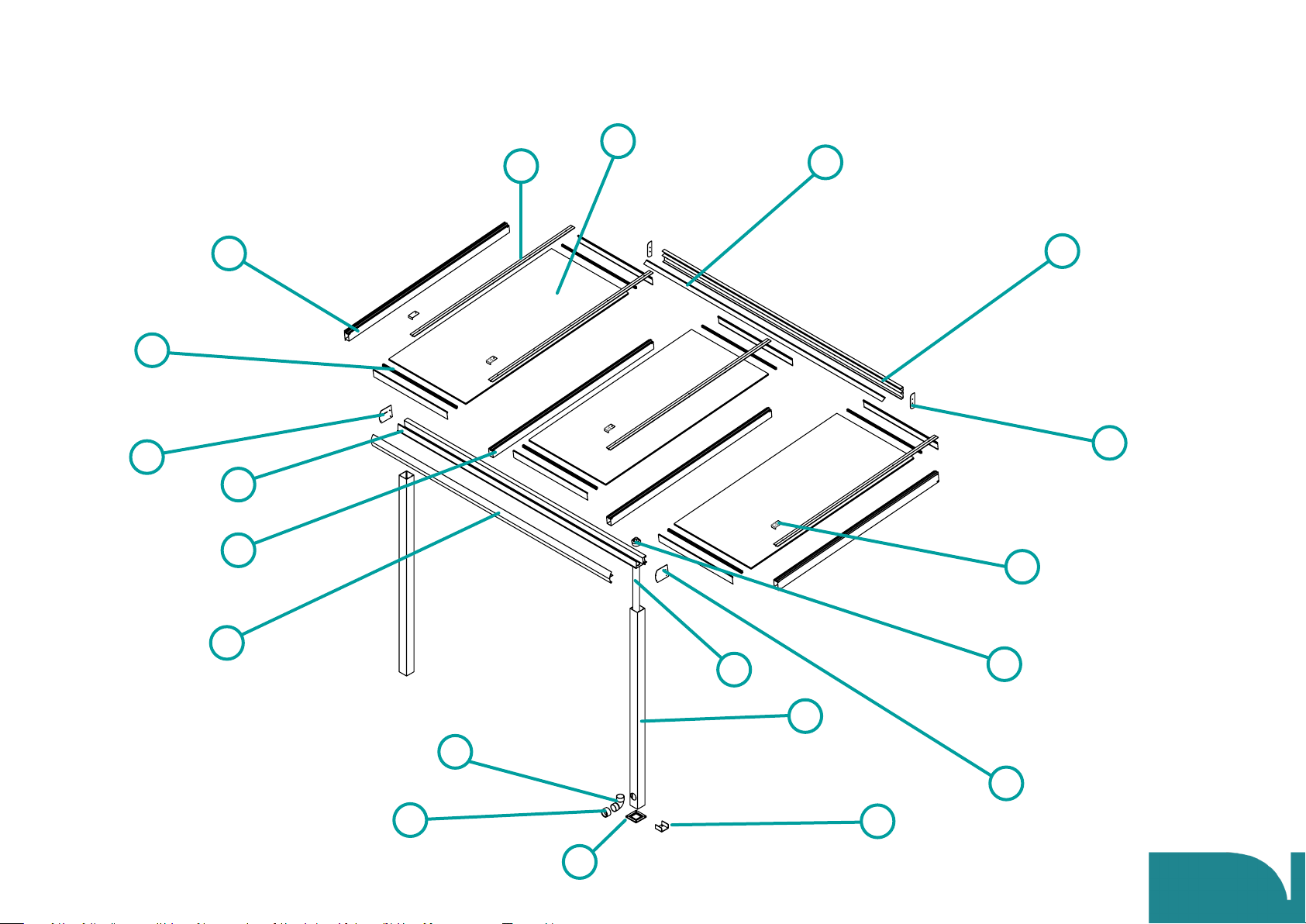
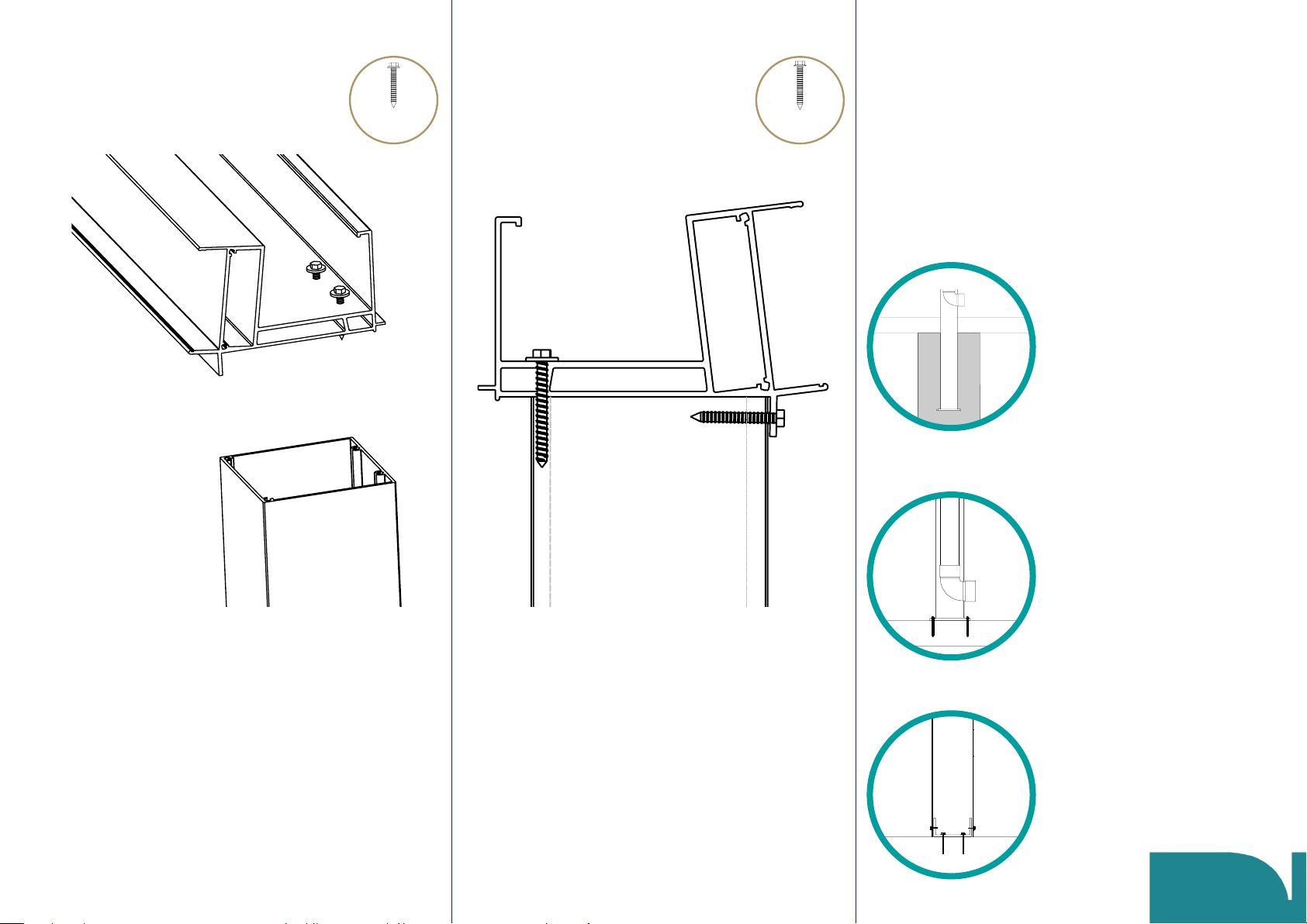
Preparing the gutter
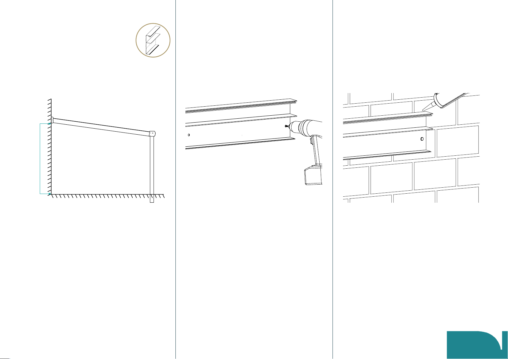
Drill pilot holes for the posts
Cut a small piece o one of the posts (the posts are
supplied over-size).
Using this o-cut as a template, place it on the gutter as
shown in the diagram above and drill pilot holes with a
1.5-2mm drill bit through the base of the gutter
wherever a post is to be xed.
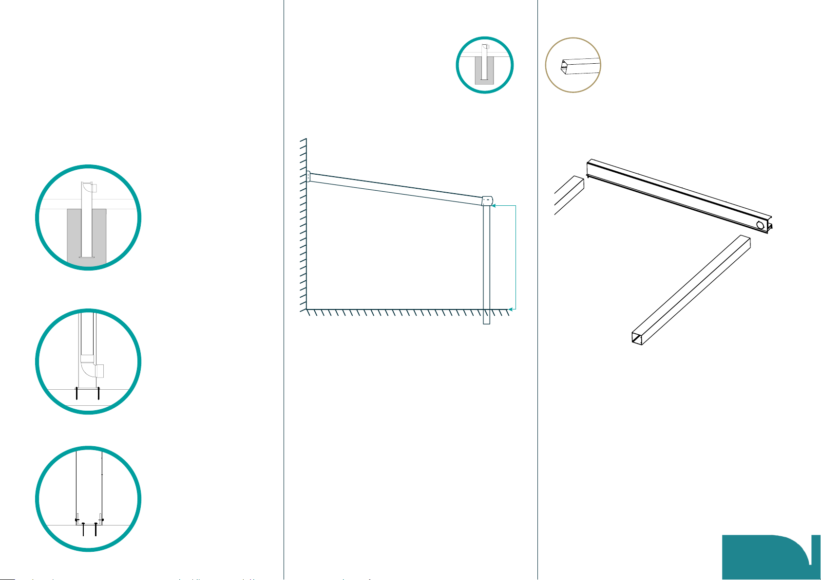
Cut a hole for the down pipe
Decide which end of the gutter the rainwater outlet will
be positioned. Drill an arbour hole in the base of the
gutter using a 62mm hole saw.
The edge of the hole must be approx. 5mm from the
rear wall of the gutter and 15-20mm from the end.
Step 2
5
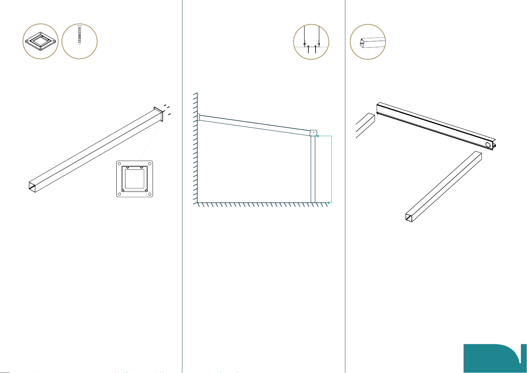
Fit steel reinforcing bar if required
If no steel bar has been supplied skip to page 7.
If your veranda has been supplied with a steel bar this
will need to be secured inside the gutter.
Place the gutter up-side-down on a pair of trestles.
Slide the steel bar into the cavity at the
back of the gutter.
The bar must sit in between the two screw-port holes
at the back of the cavity.
Drill pilot holes
Pre-drill a 4.5mm hole through the back of the gutter
into the steel bar at approx. 250mm intervals along the
length of the gutter. Be careful not to pierce the inside
wall of the gutter.
Fix the steel bar into position
Fix the steel bar into position using the 25 x 5.5mm hex
head screws provided.
500
6
25 x 5.5mm
Hex Head
The process for step 3 will be
determined by how you are
anchoring the posts
(A) Below ground (cast in concrete)
(B) Surface mounted - See page 8
(C) Concealed surface mounted - See page 9
7
(A) Preparing the posts
for below ground xing
Cut the posts to size (if necessary)
Referring to the project-specic CAD drawing, note the
gutter height (dimension “B” on the above diagram).
The posts supplied are 3000mm in length and they
should be set into the ground at least 600mm.
Add 600mm on to dimension “B” and cut the posts to
length if necessary.
Lay the posts and gutter on the ground
Lie the posts down on a clear, at surface and place the
gutter in position.
Step 3
(B) Gutter
height
Fix the base plates to one end of the posts
Using the 50 x 5.5mm CSK screws provided, x
a base plate to the bottom of each post.
Cut the posts to size
Referring to the project-specic CAD drawing, note the
gutter height (dimension “ B” on the above diagram).
The posts supplied are 3000mm in length. Cut the post
to the gutter height stated on the CAD drawing.
Lay out posts and gutter on the ground
Lie the posts down on a clear, at surface and place the
gutter in position.
(B) Gutter
height
8
(B) Preparing the posts
for surface mounting
Step 3
50 x 5.5mm
CSK Screw
Fix base plates to one end of the posts
Using the 50 x 5.5mm CSK screws provided, x
a base plate to the bottom of each post.
Cut the posts to size
Referring to the project-specic CAD drawing, note the
gutter height (dimension “B” on the above diagram).
The posts supplied are 3000mm in length. Cut the post
to the gutter height stated on the CAD drawing.
Lay out posts and gutter on the ground
Lie the posts down on a clear, at surface and place the
gutter in position.
9
(C) Preparing the
posts for concealed
surface mounted
Step 3
(B) Gutter
height
50 x 5.5mm
CSK Screw
Fixing the post to the gutter
Fix the posts to the gutter
Ensure the screw hole lugs in the top of the post line up
with the holes you have drilled in the base of the gutter.
Using 5.0 x 5.5mm hex head screws with neoprene
washers, x the base of the gutter to the top of
the posts.
Using 32 x 5.5mm hex head screws, x the lip at the
back of the gutter into the back face of the post
(2 per post).
Step 4
10
The process for step 5 will be
determined by how you are
anchoring the posts
(A) Below ground (cast in concrete)
(B) Surface mounted - See page 13
(C) Concealed surface mounted - See page 15
50 x 5.5mm
Hex Head
32 x 5.5mm
Hex Head