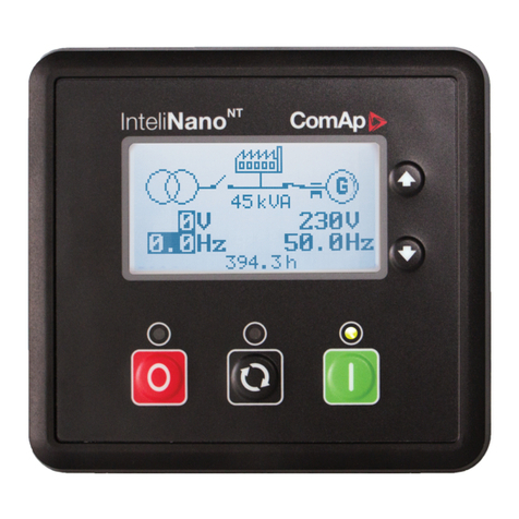
Mosa COMAP IntelliLite AMF25 User manual

MADE IN ITALY
COMAP AMF25
Codice
Code
Code
Codigo
Kodezahl
Código
CH7K20C19003
Edizione
Edition
Édition
Edición
Ausgabe
Edição
07.2019
• Unità controllo motore
• Engine control unit
• Protection moteur
• Motorschutz
• Unidad control motor
• Unidade de controlo do motor
IT
MANUALE OPERATIVO
EN
OPERATIONS MANUAL
DE
BEDIENUNGSANLEITUNG


MADE IN ITALY
COMAP AMF25
Codice
Code
Code
Codigo
Kodezahl
Código
CH7K20C19003
Edizione
Edition
Édition
Edición
Ausgabe
Edição
07.2019
• Unità controllo motore
• Engine control unit
• Protection moteur
• Motorschutz
• Unidad control motor
• Unidade de controlo do motor
MANUALE D’USO E MANUTENZIONE
ISTRUZIONI ORIGINALI - ITALIANO
lingua

02/12/16 CH7K20C1_IT-EN-DE
REV.1-07-19
INDICE
1. AVVERTENZE
....................................................................................................................................... PAG. 5
2. MODALITA’ OPERATIVE ........................................................................................................................
PAG. 5
3. CARATTERISTICHE CONTROLLER AMF25
............................................................................................. PAG. 6
4. GUIDA OPERATORE AMF25
.................................................................................................................. PAG. 7
5. SCHERMATE E STRUTTURA DELLE PAGINE ..........................................................................................
PAG. 9
6. ALLARMI..............................................................................................................................................
PAG. 9
7. SFOGLIARE GLI ALLARMI ECU ..............................................................................................................
PAG.10
8. MODIFICA SETPOINT ..........................................................................................................................
PAG.10
9. INSERIMENTO DELLA PASSWORD ......................................................................................................
PAG.11
10 REGOLAZIONE DEL CONTRASTO DELLO SCHERMO ............................................................................
PAG.11
11. SCHERMATA DELLE INFORMAZIONI SUL CONTROLLER ......................................................................
PAG.12
12. PROCEDURA RESET ORE/MANUTENZIONE .........................................................................................
PAG.12
4

02/12/16 CH7K20C1_IT-EN-DE
ITALIANO
ITALIANO
CONTROLLARE
GIORNALMENTE
Carburante Olio Batteria Acqua
!
ATTENZIONE!
Le indicazioni sull’utilizzo e funzionamento del quadro di
comando sono riferite ai quadri equipaggiati con il Controller
AMF25. Se sul vostro gruppo elettrogeno è installato
un Controller diverso CONSULTATE IL MANUALE del
dispositivo fornito in dotazione. Errori nell’utilizzo del gruppo
elettrogeno possono provocare gravi danni alle persone alla
macchina o all’impianto.
!
ATTENZIONE!
Non alterare le condizioni primarie di regolazione e non
manomettere le parti sigillate.
REV.0-12/16
CENTRALINA AMF25
2. MODALITA’ OPERATIVE
MODO OFF
Non è possibile avviare il gruppo elettrogeno. Le uscite
STARTER, GCB OPEN/CLOSE, FUEL SOLENOID non sono
attive.
Nessuna reazione se sono premuti i pulsanti: START, STOP,
GCB ON/OFF, MCB ON/OFF.
Al mancare della Rete si apre l’uscita MCB OPEN/CLOSE.
Al rientro della Rete l’uscita MCB OPEN/CLOSE si chiude con
il ritardo MCB close del.
MODO MAN (manuale)
Pulsante START avvia il gruppo elettrogeno.
Pulsante STOP arresta il gruppo elettrogeno.
Pulsante GCB ON/OFF (solo su quadri Automatici)
• Chiude GCB
• Apre GCB quando chiuso
•Se la tensione del generatore è fuori dai limiti il controller
non risponde ai comandi.
Pulsante MCB ON/OFF (solo su quadri Automatici)
•Chiude MCB
• Apre MCB quando chiuso
Avvertenze
Il motore può girare senza carico per un tempo illimitato.
Il Controller in modo Man non arresta automaticamente
il gruppo elettrogeno.
Il Controller in modo Man non avvia automaticamente il gruppo
elettrogeno al mancare della Rete.
Il Controller è provvisto di interblocco tra GCB e MCB,
questo signifi ca che non è possibile chiudere insieme i
due CB.
MODO AUT (automatico)
Il Controller non risponde ai pulsanti START, STOP, GCB ON/
OFF, MCB ON/OFF.
Quadri Automatici (Setting AMF = AMF)
Le richieste di avviamento e arresto del motore sono
determinati dalla mancanza o presenza RETE.
Quadri Manuali (Setting AMF = MRS)
Le richieste di avviamento e arresto del motore sono determinati
dallo stato dell’ingresso “Rem Start/Stop” (Start/Stop Remoto).
Le protezioni e le misure di Rete sono disabilitate.
MODO TEST
Attenzione: In modalità TEST il generatore parte
automaticamente.
Setpoint “ReturnFromTest” = MANUAL (Impostazione di
Default).
In modalità TEST il generatore è in moto senza carico, il
generatore prende carico per:
a) Mancanza Rete
b) Il pulsante MCB ON/OFF viene premuto.
Al mancare della Rete MCB si apre e successivamente GCB
si chiude.
Al rientro della Rete il carico continua ad essere alimentato dal
gruppo elettrogeno.
Per trasferire nuovamente il carico alla Rete, portare il
Controller in modo AUT e premere il pulsante MCB ON/OFF.
Il carico è trasferito automaticamente alla Rete in caso di
allarme (shut-down) sul generatore.
Setpoint “ReturnFromTest” = AUTO
Il generatore è in moto senza carico, al mancare della Rete il
MCB si apre e successivamente il GCB si chiude.
Al rientro della Rete il carico sarà trasferito automaticamente
alla Rete; il generatore continua a funzionare senza carico.
Per fermare il gruppo elettrogeno selezionare una modalità di
funzionamento diversa da TEST.
1. AVVERTENZE
!
!
5

02/12/16 CH7K20C1_IT-EN-DE
ITALIANO
ITALIANO
Modalità Operative • OFF - MAN.- AUTO - TEST
Display • Display retro-illuminato 128x64 pixel
LEDs • Tensione gruppo OK
• Guasto gruppo
• Chiusura GCB (solo per Quadro Automatico)
• Tensione rete OK (solo per Quadro Automatico)
• Mancanza rete (solo per Quadro Automatico)
• Chiusura MCB (solo per Quadro Automatico)
Pulsanti/comandi • Pulsante START
• Pulsante STOP
• Pulsante RESET ALLARMI
• Pulsante TACITAZIONE SIRENA
• Pulsanti di selezione MODE
• Pulsante chiusura/apertura GCB
• Pulsante chiusura/apertura MCB
• N° 4 pulsanti per la navigazione nei menù del controller
Misure generatore
• Tensioni : L1-L2 / L2-L3 / L3-L1 - N-L1/N-L2/N-L3
• Correnti : I1 - I2 - I3
• Potenze : kVA - kW - kVAR (totali e per fase)
• Energia : kVAh - kWh - kVARh
• Cos ϕ(medio e per fase)
• Frequenza
Misure motore • Temperatura acqua
• Pressione olio
• Livello carburante
• Velocità del motore
• Tensione di batteria
• Manutenzione
• Conta-ore
• Numero di avviamenti
Protezioni generatore • Sovraccarico
• Sovracorrente
• Corto circuito
• Sovra-sotto tensione
• Sovra-sotto frequenza
• Asimmetria di tensione
• Squilibrio di corrente
• Senso ciclico delle fasi
Protezioni motore • Sovravelocità
• Allarme e pre-allarme alta temperatura acqua
• Allarme e pre-allarme bassa pressione olio
• Allarme e pre-allarme basso livello carburante
• Alta-bassa tensione di batteria
• Guasto alternatore carica batteria
• Mancato avviamento
• Mancato arresto
• Arresto d’emergenza
• Basso livello acqua (option)
Funzioni AMF(solo per qua-
dro Automatico)
• Misura tensioni di rete : L1-L2 / L2-L3 / L3-L1 - N-L1/N-L2/N-L3
• Misura frequenza di rete
• Rilevamento trifase
• Sovra-sotto tensione di rete
• Sovra-sotto frequenza di rete
• Asimmetria tensione di rete
• Senso ciclico delle fasi di rete
• Gestione in mutuo soccorso di due gruppi in emergenza
Caratteristiche • Storico eventi e allarmi
• Due Timer programmabili indipendenti (Test automatico o partenze programmate)
• Gestione del minimo giri motore (Idle)
• Start e Stop da segnale esterno
• Preriscaldo
• Due lingue selezionabile (altre a richiesta)
• Programmazione da pannello o da PC
• Collegamento diretto a motori con ECU via Can Bus J1939
• Ingressi e uscite programmabili (solo da PC)
• Protezione IP 65
• Temperatura di funzionamento : -20°C / +70°C
Comunicazione • Modbus RTU (richiede scheda Optional con uscita RS 232 e RS485)
• Modbus TCP/IP (richiede scheda Optional Ethernet con uscita RJ45)
• Modbus SNMP (richiede scheda Optional Ethernet con uscita RJ45)
• Internet (richiede scheda Optional Ethernet con uscita RJ45)
• GSM/GPRS ( richiede scheda Optional con Modem integrato) per il controllo wireless del gruppo via SMS
o Internet
REV.0-12/16
CENTRALINA AMF25
3. CARATTERISTICHE CONTROLLER AMF25
6

02/12/16 CH7K20C1_IT-EN-DE
ITALIANO
ITALIANO
REV.0-12/16
CENTRALINA AMF25
Start
I
Enter
Stop
0
Fault
reset
I
Horn
reset
Mode
Page
Mode
I/ 0I/ 0
15
16
17
5 6
1
2
3
4
9
10
11
781213141918
POSIZIONE PULSANTE DESCRIZIONE
1PULSANTE DI AVVIO:Funziona solo in modalità manuale. Premere questo pulsante per
far partire la sequenza di avvio del motore.
2
PULSANTE DI ARRESTO: Funziona solo in modalità manuale. Premere questo pulsante
per avviare la sequenza di arresto del gruppo elettrogeno. Premendo ripetutamente o tenen-
do premuto il pulsante per più di 2 secondi, viene annullata la fase attuale della sequenza di
arresto (come il raffreddamento) e si passa alla fase successiva (arresto immediato).
3
PULSANTE FAULT RESET: Usare questo pulsante per riconoscere gli allarmi e disattivare
l’uscita sonora. Gli allarmi inattivi scompariranno immediatamente e lo stato degli allarmi
attivi passerà a “confermato”, quindi scompariranno appena ne verrà rimossa la causa.
4PULSANTE DI RESET SONORO: Usare questo pulsante per disattivare l’uscita sonora
senza riconoscere gli allarmi.
5Mode
PULSANTE DI MODALITA’ SINISTRA: Usare questo pulsante per cambiare la modalità.
Il pulsante funziona solo se viene visualizzata la schermata principale con l’indicatore della
modalità attualmente selezionata.
Nota: Questo pulsante non funziona se la modalità del controller viene forzatamente attivata
da una delle uscite binarie Remoto OFF, Remoto MAN, Remoto AUT, Remoto TEST.
6Mode
PULSANTE DI MODALITA’ DESTRA: Usare questo pulsante per cambiare la modalità. Il
pulsante funziona solo se viene visualizzata la schermata principale con l’indicatore della
modalità attualmente selezionata.
Nota: Questo pulsante non funziona se la modalità del controller viene forzatamente attivata
da una delle uscite binarie Remoto OFF, Remoto MAN, Remoto AUT, Remoto TEST.
7I/ 0
PULSANTE GCB: Funziona solo in modalità manuale. Premere questo pulsante per aprire
o chiudere manualmente il GCB. Notare che devono veri carsi determinate condizioni, altri-
menti la chiusura del GCB è bloccata.
8I/ 0
PULSANTE MCB: Funziona solo in modalità manuale. Premere questo pulsante per aprire
o chiudere manualmente il MCB (Solo su quadri Automatici).
Attenzione!
Con questo pulsante si può disconnettere il carico dall’alimentazione di rete! Agire solo se si
è certi di quello che si sta facendo!
PULSANTI DI CONTROLLO DEL GRUPPO ELETTROGENO
4. GUIDA OPERATORE AMF25
7

02/12/16 CH7K20C1_IT-EN-DE
ITALIANO
ITALIANO
POSIZIONE PULSANTE DESCRIZIONE
15 Schermo graco bianco e nero, 128x64 pixel
16
PULSANTE PAGINA: Usare questo pulsante per passare alla schermata delle pagine.
Vedere il capitolo relativo alle schermate e alla struttura delle pagine sotto la tabella per
maggiori dettagli.
17 PULSANTE SU: Usare questo pulsante per muovere verso l’alto o incrementare un valore.
18 PULSANTE GIU’: Usare questo pulsante per muovere verso il basso o decrementare un
valore.
19 Enter PULSANTE INVIO: Usare questo pulsante per terminare la modica di un setpoint o muo-
vere a destra nella pagina della storia.
POSIZIONE DESCRIZIONE
9
GUASTO AL GRUPPO ELETTROGENO: Il LED ROSSO comincia a lampeggiare se c’è un guasto al gruppo
elettrogeno. Dopo aver premuto il pulsante FAULT RESET, la luce si fa ssa (se un allarme è ancora attivo) o
si spegne (se non c’è allarme attivo).
10 TENSIONE DEL GRUPPO ELETTROGENO OK: Il LED VERDE è acceso se la tensione del generatore è
presente e dentro i limiti.
11 GCB ON: Il LED VERDE è acceso se il GCB è chiuso. E’ attivato dall’uscita CHIUDI/APRI GCB o dal segnale
di feedback del GCB (AMF 25) (Solo su quadri Automatici)
12 MCB ON: Il LED VERDE è acceso se il MCB è chiuso. E’ attivato dall’uscita CHIUDI/APRI MCB o dal segnale
di feedback dell’MCB (AMF 25) (Solo su quadri Automatici)
13 TENSIONE DI RETE OK: Il LED VERDE è acceso, se la tensione di rete è presente e dentro i limiti (Solo su
quadri Automatici).
14 GUASTO DI RETE: Il LED rosso comincia a lampeggiare se viene rilevato un guasto di rete e, all’avvio del
gruppo elettrogeno, si fa sso nché il guasto di rete non viene rimosso (Solo su quadri Automatici).
INDICATORI OPERATIVI DEL GRUPPO ELETTROGENO
PULSANTI DELLO SCHERMO E DI CONTROLLO
REV.0-12/16
CENTRALINA AMF25
8

02/12/16 CH7K20C1_IT-EN-DE
ITALIANO
ITALIANO
REV.0-12/16
CENTRALINA AMF25
5. SCHERMATE E STRUTTURA DELLE PAGINE
Le informazioni visualizzate vengono strutturate in “pagine” e “schermate”. Usare il pulsante PAGINA per sfogliare le pagine.
1. La pagina Misurazione consiste di schermate che visualizzano i valori misurati, come la tensione, la corrente, la pressione
dell’olio, ecc., i valori calcolati come ad esempio la potenza del gruppo elettrogeno, i dati statistici e la lista degli allarmi
nell’ultima schermata.
2. La pagina Setpoint contiene tutti i setpoint organizzati in gruppi ed anche un gruppo speciale per inserire la password.
3. La pagina Storia mostra la storia, visualizzando per prima l’ultima registrazione.
Nota:
Le pagine di storia e dei setpoint sono disponibili solo se si seleziona l’interfaccia Ingegnere (non l’interfaccia Utente). Vedi il
sottocapitolo Schermata delle informazioni sul controller qui di seguito.
6. ALLARMI
Misurazione Setpoint Storia
Generator
L1N 0V0 L1L2
L1N 0V0 L1L2
L1N 0V0 L1L2
Gen freq
0
0.0Hz
0 0 A
OFFMAN AUTTEST !
Notready
MainsFlt
PF 0.00
RPM 0
0 kW
No Timer
0
ECU AlarmList
FC
>EngOil Press
000225 (000E1h)
100 OC 4 FMI 1
1AlarmList
Emergency Stop
Password
Page
Gen-set Name
200 kW
350 A
>Basic Settings
Engine Params
Engine Protect
Gener Protect
AutoMains Fail
Extension I/O
Date/Time
2000 /5A
Gen-set Name
>Nominal Power
Nomin Current
CT Ratio
200 kW
350 A
2000 /5A
>Nominal Power
250
Nomin Current
CT Ratio
No. Reason
13:02:17 07/08/2008
Time Date
>0Switched On
-1 Fault reset
-2 Emergency Stop
-3 Wrn RA15 Fail
-4 Sprinkler Set
-5 Config Loaded
0 Switched On
Mode RPM Pwr
0 0
0 0
0 0
0 0
0 0
>13:02:17 07/08/2008
13:00:46 07/08/2008
13:00:46 07/08/2008
13:00:45 07/08/2008
13:00:45 07/08/2008
13:00:43 07/08/2008
0 0
>OFF
OFF
OFF
OFF
OFF
OFF
0 Switched On
Page
Page
Page
Page
Page
Page
Page
Enter
Enter
Enter
EnterPage
EnterEnterPage
AlarmList 3
*MCB Fail
*Emergency Stop
Sd Override
Allarme inattivo non confermato
Allarme attivo non confermato
Allarme attivo confermato
9

02/12/16 CH7K20C1_IT-EN-DE
ITALIANO
ITALIANO
REV.0-12/16
CENTRALINA AMF25
7. SFOGLIARE GLI ALLARMI ECU
8. MODIFICA SETPOINT
Notready
OFFMAN AUTTEST !
MainsFlt
PF 0.00
RPM 0
No Timer
0 kW 0
Password
EnterPage
EnterEnterPage
>Basic Settings
Engine Params
Engine Protect
Gener Protect
AutoMains Fail
Extension I/O
Date/Time
Page
Gen-set Name
>Nominal Power
350 A
200 kW
*Nomin Current
CT Ratio
2000 /5A
Gen-set Name
250
>Nominal Power
200 kW
350
*Nomin Current
A
CT Ratio
2000 /5A
Nota:
Non si può modificare il
I setpointsetpoint?
contrassegnati da un
asterisco sono protetti da
password. Inserire la
password come descritto
nel capitolo Inserimento
della password qui di
seguito.
10

02/12/16 CH7K20C1_IT-EN-DE
ITALIANO
ITALIANO
REV.0-12/16
CENTRALINA AMF25
9. INSERIMENTO DELLA PASSWORD
Not ready
MainsFlt
OFF MANAUT TEST !
PF 0.00
RPM 0
No Timer
00 kW
>EnterPassword
Changepassword
Enter
>Password
Basic Settings
Engine Params
Engine Protect
Gener Protect
AutoMains Fail
Extension I/O
Date/Time
Page
EnterEnterPage
25
Page
>EnterPassword
Changepassword
Nota:
Password perduta? Visualizza la
schermata delle informazioni
contenente il numero seriale ed il
numero di decodificazione della
password come descritto nel
capitolo qui di seguito e li invia al
distributore locale.
10. REGOLAZIONE DEL CONTRASTO DELLO SCHERMO
OFF MAN AUT TEST !
MainsFlt
Not ready
RPM 0
PF 0.00
No Timer
0 kW 0
Enter +
Enter +
OFFMAN AUT TEST !
Not ready
MainsFlt
RPM
PF 0.00
0
No Timer
0 kW 0
OFFMAN AUT TEST !
Not ready
MainsFlt
PF 0.00
RPM 0
No Timer
0 kW 0
11

02/12/16 CH7K20C1_IT-EN-DE
ITALIANO
ITALIANO
11. SCHERMATA DELLE INFORMAZIONI SUL CONTROLLER
OFFMAN AUT TEST !
Not ready
MainsFlt
PF 0.00
RPM 0
No Timer
0 kW 0
InteliLite NT
ComAp 2007-2008
Page
Languages
>English
Chinese
Enter + Page
IL-NT-x.y
Serial:12345678
SW ver: x.y, x.y
Appl : AMF25
Branch: Standard
User
User interface:
>Engineer
Page
Page
Serial: 12345678
Pwd. dec.: 1234567890
Enter
Enter
CENTRALINA AMF25
12. PROCEDURA RESET ALLARME ORE/MANUTENZIONE
POSIZIONE PULSANTE DESCRIZIONE
1Inserire la Password come indicato nel Paragrafo 9.
(se la password non è stata modicata precedentemente è 25)
2A password inserita premere il tasto PAGE.
3Premere ↓ no a selezionare ENGINE PROTECT (Protezione Motore) e premere ENTER.
4Premere ↓ no a selezionare WRN MAINTENANCE (Avs Assist) e premere ENTER.
5
Premere ↑ per impostare le ore del successivo intervento di manutenzione.
(Impostare le ore seguendo le instruzioni del libretto d’uso e manutenzione del motore o le
indicazioni del manutentore)
6Premere PAGE per 3 volte per tornare alla pagina iniziale.
REV.1-07-19
12

MADE IN ITALY
COMAP AMF25
Codice
Code
Code
Codigo
Kodezahl
Código
CH7K20C19003
Edizione
Edition
Édition
Edición
Ausgabe
Edição
07.2019
• Unità controllo motore
• Engine control unit
• Protection moteur
• Motorschutz
• Unidad control motor
• Unidade de controlo do motor
USE AND MAINTENANCE MANUAL
TRANSLATION OF THE ORIGINAL INSTRUCTIONS – ENGLISH
language
13

14

02/12/16 CH7K20C1_IT-EN-DE
INDEX
1. WARNING
............................................................................................................................................ PAG.16
2. OPERATING MODES .............................................................................................................................
PAG.16
3. AMF25 CONTROLLER CHARACTERISTICS
................................................................................................... PAG.17
4. OPERATOR INTERFACE AMF25
............................................................................................................ PAG.18
5. DISPLAY SCREENS AND PAGES STRUCTURE ........................................................................................
PAG.20
6. ALARMS ..............................................................................................................................................
PAG.20
7. BROWSING ECU ALARMS.....................................................................................................................
PAG.21
8. SETPOINT CHANGE .............................................................................................................................
PAG.21
9. ENTERING THE PASSWORD ................................................................................................................
PAG.22
10 DISPLAY CONTRAST ADJUSTMENT.....................................................................................................
PAG.22
11. CONTROLLER INFORMATION SCREEN................................................................................................
PAG.23
12. PROCEDURE FOR HOUR/MAINTENANCE ALERT RESET .......................................................................
PAG.23
REV.1-07-19
15

02/12/16 CH7K20C1_IT-EN-DE
ENGLISH
ENGLISH
CHECK DAILY
THE WARNING
LIGHTS
Fuel Oil Battery Wather
!
CAUTION!
The indications on the use and operation of the control panel
are referred to the control panels equipped with the AMF25
Controller. If your generator is installed with a different
Controller REFER TO THE THE MANUAL of the device
provided. Errors in the use of the generator can cause severe
injury to people, the machine or the plant.
!
CAUTION!
Do not alter the primary conditions of regulation and do not
touch the sealed parts.
REV.0-12/16
2. OPERATING MODES
MODO OFF
You cannot start the generator. The STARTER, GCB OPEN/
CLOSE, FUEL SOLENOID exits are inactive.
There is no reaction if the buttons: START, STOP, GCB ON/
OFF, MCB ON/OFF are pressed.
The exit MCB OPEN/CLOSE opens in the case of a Power
failure.
When the power is restored the exit MCB OPEN/CLOSE
closes with the MCB close delay.
MAN. (Manual) MODE
The START button starts the generator.
The STOP button stops the generator.
The GCB ON/OFF button (only on Automatic control panels)
• Closes GCB
• Open GCB when closed
• If the generator voltage is out of the limits, the controller
does not respond to commands.
The MCB ON/OFF button (only on Automatic control panels)
• Closes MCB
• Open MCB when closed
Warnings
The engine can run without charge for an unlimited
time. The Controller in Man. mode does not automatically stop
the generator.
The Controller in Man. mode does not automatically start up
the generator in case of a Power failure.
The Controller is equipped with interlock between GCB
and MCB; this means that you cannot close the two CBs
together.
AUT. (Automatic) MODE
The Controller does not respond to the START, STOP, GCB
ON/OFF MCB ON/OFF buttons.
Automatic Control Panels (Setting AMF = AMF)
Engine start and stop requests are determined by the absence
or presence of the POWER.
Manual Conrol Panels (Setting AMF = MRS)
Engine start and stop requests are determined by the state of
the “Rem. Start/Stop” (Remote Start/Stop) input. The POWER
NETWORK protection and measures are disabled.
TEST MODE
Attention: In the TEST mode, the generator starts
automatically.
Setpoint “ReturnFromTest” = MANUAL (Default setting).
In the TEST mode, the generator is running without charge,
the generator takes charge for:
a) Power Failure
b) The MCB ON/OFF button is pressed.
In the case of a Power failure, the MCB opens and subsequently,
the GCB closes.
When the Power is restored, the charge continues to be
powered by the generator.
To transfer the charge to the Power Network again, move the
Controller in AUT. Mode and press the MCB ON/OFF button.
The charge is transferred automatically to the Power Network
in case of an alarm (shut-down) on the generator.
Setpoint “ReturnFromTest” = AUTO
The generator is running without charge, in case of a Power
fail the MCB opens and subsequently the GCB closes.
When the Power is restored, the charge will be transferred
automatically to the Power Network; the generator keeps
running without charge.
To stop the generator select an operating mode other than
TEST.
CONTROLLER AMF25
!
!
1. WARNING
16

02/12/16 CH7K20C1_IT-EN-DE
ENGLISH
ENGLISH
REV.0-12/16
CONTROLLER AMF25
Operating mode • OFF - MAN.- AUTO - TEST
Display • Graphic back-light LCD display 128x64 pixels
LEDs • Gen-set voltage OK
• Gen-set failure
• GCB ON (only for Automatic transfer unit)
• Mains voltage OK (only for Automatic transfer unit)
• Mains failure (only for Automatic transfer unit)
• MCB ON (only for Automatic transfer unit)
Buttons • START button
• STOP button
• FAULT RESET button
• RESET HORN button
• MODE selection button
• Pulsante chiusura/apertura GCB button
• Pulsante chiusura/apertura MCB button
• N° 4 buttons for controller programming
Generator Measures
• Voltage : L1-L2 / L2-L3 / L3-L1 - N-L1/N-L2/N-L3
• Current : I1 - I2 - I3
• Powers : kVA - kW - kVAR (totali e per fase)
• Energy : kVAh - kWh - kVARh
• Cos ϕ(medium and per phase)
• Frequency
Engine Measures • Water temperature
• Oil pressure
• Fuel level
• Rpm meter
• Battery voltage
• Maintance
• Hours meter
• Starts number
Generator Protections • Overload
• Overcurrent
• Short circuit
• Over-Udervoltage
• Over-Uderfrequency
• Voltage asymmetry
• Unbalanced current
• Phase sequence
Engine Protections • Overspeed
• High water temperature warning
• Low oil pressure warning
• Low fuel level warning
• Over-Uder battery voltage
• Battery charge alternator failure
• Start failure
• Stop failure
• Emergency stop
• Low water level shudown (option)
AMF functins (Automatic control
panel only)
• Measure mains voltage : L1-L2 / L2-L3 / L3-L1 - N-L1/N-L2/N-L3
• Measure mains frequency
• Three phase detection
• Over-Under mains voltage
• Over-Under mains frequency
• Voltage asymmetry
• Phase sequence
• Dual mutual stand-by application
Features • Event log and alarms
• 2 tests run scheduler (Automatic test or scheduled starts)
• Engine idle management (Idle)
• Remote Start and Stop
• Pre-heating
• 2 selectable languages (other languages available)
• Setpoints adjustable via controller buttons or PC
• Direct connection to engines with ECU via Can bus J1939
• Congurable inputs and outputs (only via PC)
• IP65 protection
• Operation temperature: -20°C / +70°C
Communication • RTU Modbus (optional board with RS232 & RS485 outputs is needed)
• TCP/IP Modbus (optional Ethernet board with RJ45 output is needed)
• SNMP Modbus (optional Ethernet board with RJ45 output is needed)
• Internet (optional Ethernet board optional is needed)
• GSM/GPRS (integrated Modem board optional is needed) for Gen-set remote control via SMS or internet
3. AMF25 CONTROLLER CHARACTERISTICS
17

02/12/16 CH7K20C1_IT-EN-DE
ENGLISH
ENGLISH
REV.0-12/16
CONTROLLER AMF25
POSITION BUTTON DESCRIPTION
1START BUTTON: Works in MAN mode only. Press this button to initiate the start sequence
of the engine.
2
STOP BUTTON: Works in MAN mode only. Press this button to initiate the stop sequence
of the gen-set. Repeated pressing or holding the button for more than 2s will cancel current
phase of stop sequence (like ramping the power down or cooling) and next phase will con-
tinue.
3
FAULT RESET BUTTON: Use this button to acknowledge alarms and deactivate the horn
output. Inactive alarms will disappear immediately and status of active alarms will be chan-
ged to “con rmed” so they will disappear as soon as their reasons dismiss.
4HORN RESET BUTTON: Use this button to deactivate the horn output without acknowled-
ging the alarms.
5Mode
MODE LEFT BUTTON: Use this button to change the mode. The button works only if the
main screen with the indicator of currently selected mode is displayed.
Note: This button will not work if the controller mode is forced by one of binary inputs Remo-
te OFF, Remote MAN, Remote AUT, Remote TEST.
6Mode
MODE RIGHT BUTTON: Use this button to change the mode. The button works only if the
main screen with the indicator of currently selected mode is displayed.
Note: This button will not work if the controller mode is forced by one of binary inputs Remo-
te OFF, Remote MAN, Remote AUT, Remote TEST.
7I/ 0GCB BUTTON: Works in MAN mode only. Press this button to open or close the GCB ma-
nually. Note that certain conditions must be valid otherwise GCB closing is blocked.
8I/ 0
MCB BUTTON: Works in MAN mode only. Press this button to open or close the MCB ma-
nually.
Caution!
You can disconnect the load from the mains supply with this button! Be sure you know well
what you are about to do!
GEN-SET CONTROL BUTTONS
Start
I
Enter
Stop
0
Fault
reset
I
Horn
reset
Mode
Page
Mode
I/ 0I/ 0
15
16
17
5 6
1
2
3
4
9
10
11
781213141918
4. OPERATOR INTERFACE AMF 25
18

02/12/16 CH7K20C1_IT-EN-DE
ENGLISH
ENGLISH
POSITION BUTTON DESCRIPTION
15 Graphic B/W display, 128x64 pixels
16 PAGE BUTTON: Use this button to switch over display pages. See Display Screens and
Pages Structure chapter below this table for more details.
17 UP BUTTON: Use this button to move up or increase a value.
18 DOWN BUTTON: Use this button to move down or decrease a value.
19 Enter ENTER BUTTON: Use this button to nish editing a setpoint or moving right in the history
page.
POSITION DESCRIPTION
9GEN-SET FAILURE: Red LED starts ashing when gen-set failure occurs. After FAULT RESET button is pres-
sed, goes to steady light (if an alarm is still active) or is off (if no alarm is active).
10 GEN-SET VOLTAGE OK: Green LED is on if the generator voltage is present and within limits.
Note: The limits for the generator voltage and frequency are given by setpoints in the Gener Protect group.
11 GCB ON: Green LED is on, if GCB is closed. It is driven by GCB CLOSE/OPEN output (AMF 8/9) or by GCB
feedback signal (AMF 20/25).
12 MCB ON: Green LED is on, if MCB is closed. It is driven by MCB CLOSE/OPEN output (AMF 8/9) or by MCB
feedback signal (AMF 20/25).
13 MAINS VOLTAGE OK: Green LED is on, if mains is present and within limits.
14 MAINS FAILURE: Red LED starts blinking when the mains failure is detected and after the gen-set has started
and connected to the load it lights permanently until the mains failure disappears.
GEN-SET OPERATION INDICATORS
DISPLAY AND CONTROL BUTTONS
REV.0-12/16
CONTROLLER AMF25
19

02/12/16 CH7K20C1_IT-EN-DE
ENGLISH
ENGLISH
REV.0-12/16
CONTROLLER AMF25
5. DISPLAY SCREENS AND PAGES STRUCTURE
The displayed information is structured into “pages” and “screens”. Use PAGE button to switch over the pages.
1. The page Measurement consists of screens which display measured values like voltages, current, oil pressure etc.,
computed values like i.e. gen-set power, statistic data and the alarm list on the last screen.
2. The page Setpoints contains all setpoints organized to groups and also a special group for entering password.
3. The page History log shows the history log in the order that the last record is displayed rst.
NOTE:
History and Setpoints pages are available only when you choose Engineer interface (not User). See Controller Information
Screen subchapter below.
6. ALARMS
Misurazione Setpoint Storia
Generator
L1N 0V0 L1L2
L1N 0V0 L1L2
L1N 0V0 L1L2
Gen freq
0
0.0Hz
0 0 A
OFFMAN AUTTEST !
Notready
MainsFlt
PF 0.00
RPM 0
0 kW
No Timer
0
ECU AlarmList
FC
>EngOil Press
000225 (000E1h)
100 OC 4 FMI 1
1AlarmList
Emergency Stop
Password
Page
Gen-set Name
200 kW
350 A
>Basic Settings
Engine Params
Engine Protect
Gener Protect
AutoMains Fail
Extension I/O
Date/Time
2000 /5A
Gen-set Name
>Nominal Power
Nomin Current
CT Ratio
200 kW
350 A
2000 /5A
>Nominal Power
250
Nomin Current
CT Ratio
No. Reason
13:02:17 07/08/2008
Time Date
>0Switched On
-1 Fault reset
-2 Emergency Stop
-3 Wrn RA15 Fail
-4 Sprinkler Set
-5 Config Loaded
0 Switched On
Mode RPM Pwr
0 0
0 0
0 0
0 0
0 0
>13:02:17 07/08/2008
13:00:46 07/08/2008
13:00:46 07/08/2008
13:00:45 07/08/2008
13:00:45 07/08/2008
13:00:43 07/08/2008
0 0
>OFF
OFF
OFF
OFF
OFF
OFF
0 Switched On
Page
Page
Page
Page
Page
Page
Page
Enter
Enter
Enter
EnterPage
EnterEnterPage
AlarmList 3
*MCB Fail
*Emergency Stop
Sd Override
Allarme inattivo non confermato
Allarme attivo non confermato
Allarme attivo confermato
Measurement History log
Inactive unconrmed alarm
Active unconrmed alarm
Active conrmed alarm
20
This manual suits for next models
1
Table of contents
Languages:
Other Mosa Control Unit manuals
Popular Control Unit manuals by other brands

Wallbox
Wallbox Commander 2 installation guide

Jetter
Jetter JetWeb JX2-CNT1 user manual

PICO
PICO TA369 user guide

Test Equipment Depot
Test Equipment Depot Skutch CK-2 quick start guide

Mallory
Mallory HYFIRE IV SERIES installation instructions

HYDAC International
HYDAC International FCU 1000 Series Operating and maintenance instructions