1
INSTALLATION
NOTE: Prior to installation of the ZW205FP, ensure that all debris is
ushed out the piping system before installed.
1. During the installation of a ZW205FP in a sprinkler system, Underwriter
Laboratories (UL) requires NFPA 13 “Standard for Installation of Sprinkler
Systems” and NFPA 20 "Standard for the Installation of Stationary Pumps
for Fire Protection" be followed.
2. Upon installation UL also requires that the ZW205FP be tested in
accordance with NFPA 13 or NFPA 20. Thereafter the valve shall be in-
spected, tested, and maintained in accordance to NFPA 25 “Standard for
the Inspection, Testing, and Maintenance of Water-Based Fire Protection
Systems”.
3. For making adjustments and servicing allow for adequate space
around the valve.
4. PositiontheZW205FPinlinematchingthedirectionofowasindi-
catedonthevalvemodeltagwiththeproperdirectionofowinthesystem.
Once attached to line, double check all fasteners/bolts in the pilot system
and on main valve are tight and there is no damage prior to pressurizing
system.
NOTE: Pressure in some applications can be very high so be thor-
ough in checking and inspecting for proper installation and makeup.
6. Zurn Wilkins valves are designed to operate in both the vertical and
horizontal positions. However, it is recommended that ZW205FP’s 6” and
larger, be installation in the horizontal position.
The horizontal positioning of the larger valves avoids premature wear due to
mass of plunger assemblies as well as allows for greater accessibility during
annual inspections, and maintenance.
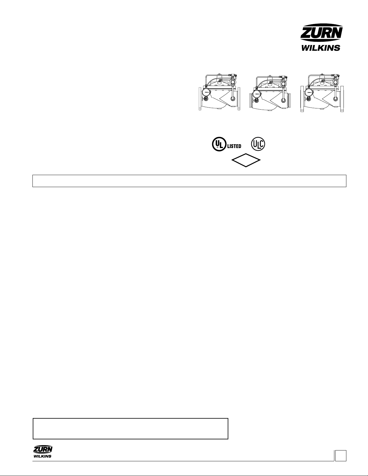
Installation Start-up Maintenance Instructions
Model ZW205FP
Fire Pump Relief Valve
Globe and Angle Pattern Bodies
2", 2-1/2", 3", 4", 6", 8", & 10"
ZW205FP
Class 150 Flanged
Max 250 psi Inlet
ZW205FPG
Grooved
Max 300 psi Inlet
ZW205FPY
Class 300 Flanged
Max 300 psi Inlet
START-UP
CAUTION: To prevent personnel injury and damage to equipment
check that downstream venting is adequate prior to start-up and
test procedures. All adjustments under
pressure should be made slowly. If the main valve opens or closes
too fast it may cause surging in upstream piping.
1. Prior to pressurizing the valve assembly, it is also recommended that
a ZPI valve position indicator be installed to aid in verifying proper valve
movement. Pressurize the upstream side of the ZW205FP.
2. Asthevalveisllingwithwater,itisnecessarytobleedthemain
valve and pilot system of air. To vent air, partially open or loosen the high-
estplugsorttingsinthesystem.TheZPIvalvepositionindicatorisa
great location, as it has a test cock at the top to vent air pressure. It may
be necessary to bleed system more than once. After removal of air in the
systemtightenallloosettings.NOTE: If valve is installed vertically, it
will be necessary to loosen some upper cover bolts until you have
vented all the air from the cover chamber.
3. One can adjust the set pressure of the control valve by one of three
different procedures. Choose one based on the capabilities of the re
protection system
a. Close all discharge lines from the re pump so all ow goes
through the ZW205FP. Loosen the pilot adjustment screw all the way
tolowerthesetreliefpressure.Turnontherepumptopressurizethe
upstream side of the ZW205FP. Note: The control valve should open
and allow a lot of water to ow. If there is no ow, continue turning
the pilot adjustment screw counterclockwise.Oncewaterisowing
through the control valve, slowly turn the pilot valve adjustment screw
clockwise. As the screw is tightened the control valve will slowly start to
close causing upstream pressure to increase. Continue turning adjust-
ment screw clockwise until upstream pressure is stable at the desired
relief set pressure.
Installation / Start-up
DESCRIPTION
The Zurn Wilkins Model ZW205FP Fire Pump Pressure Relief Valve
isdesignedspecicallyforFireSuppressionSystemstorelievehigh
system pressures. The pilot assembly reacts quickly to increases
of upstream pressure to prevent damage to system piping, valves,
andsprinklerswhilemaintainingpositivepressureonrepumps.As
thewaterdemandincreasesintheresuppressionsystemtherelief
valvewillstarttoclose,directingmorewatertosuppressres.The
relief valve will maintain the upstream pressure at the set pressure as
longasmaximumowratesofthevalvearenotexceeded.TheZurn
Wilkins Model ZW205FP is design to open quickly and close slowly to
prevent upstream pressure surges. In addition the Model ZW205FP
comes standard with red epoxy coating internally and externally for
corrosion protection, as well an inlet pressure gauge for quick and easy
maintenance or repair. The ZW205FP is available in both globe and
angle pattern bodies.
ZW205FPTH
Threaded
Max 300 psi Inlet
ZURN WILKINS
1747 Commerce Way, Paso Robles, CA 93446 Phone:855-663-9876 Fax:805-238-5766
www.zurn.com
LISTED
FM
!WARNING: Cancer and Reproductive Harm - www.P65Warnings.ca.gov
!ADVERTENCIA: Cáncer y daño reproductivo - www.P65Warnings.ca.gov
!AVERTISSEMENT: Cancer et néfastes sur la reproduction - www.P65Warnings.ca.gov


