Mosa VTG3300 SERIES User manual

Trunking Gateway
VTG3300 Series
User Guide
Edition 1.0
Updated: 2005/08/01


VTG3300 Series user guide
Table of Contents
1. SAFETY INSTRUCTIONS.................................................................................................................................... 3
2. PREFACE ................................................................................................................................................................ 4
3. FEATURE DESCRIPTIONS ................................................................................................................................. 5
3.1. BASIC AND ADVANCED FEATURES ..........................................................................................................5
3.2. PBX FEATURES ...................................................................................................................................5
3.3. OTHER SPECIAL FEATURES ...................................................................................................................6
4. PACKAGE CONTENTS ........................................................................................................................................ 7
5. GENERAL DESCRIPTIONS ................................................................................................................................8
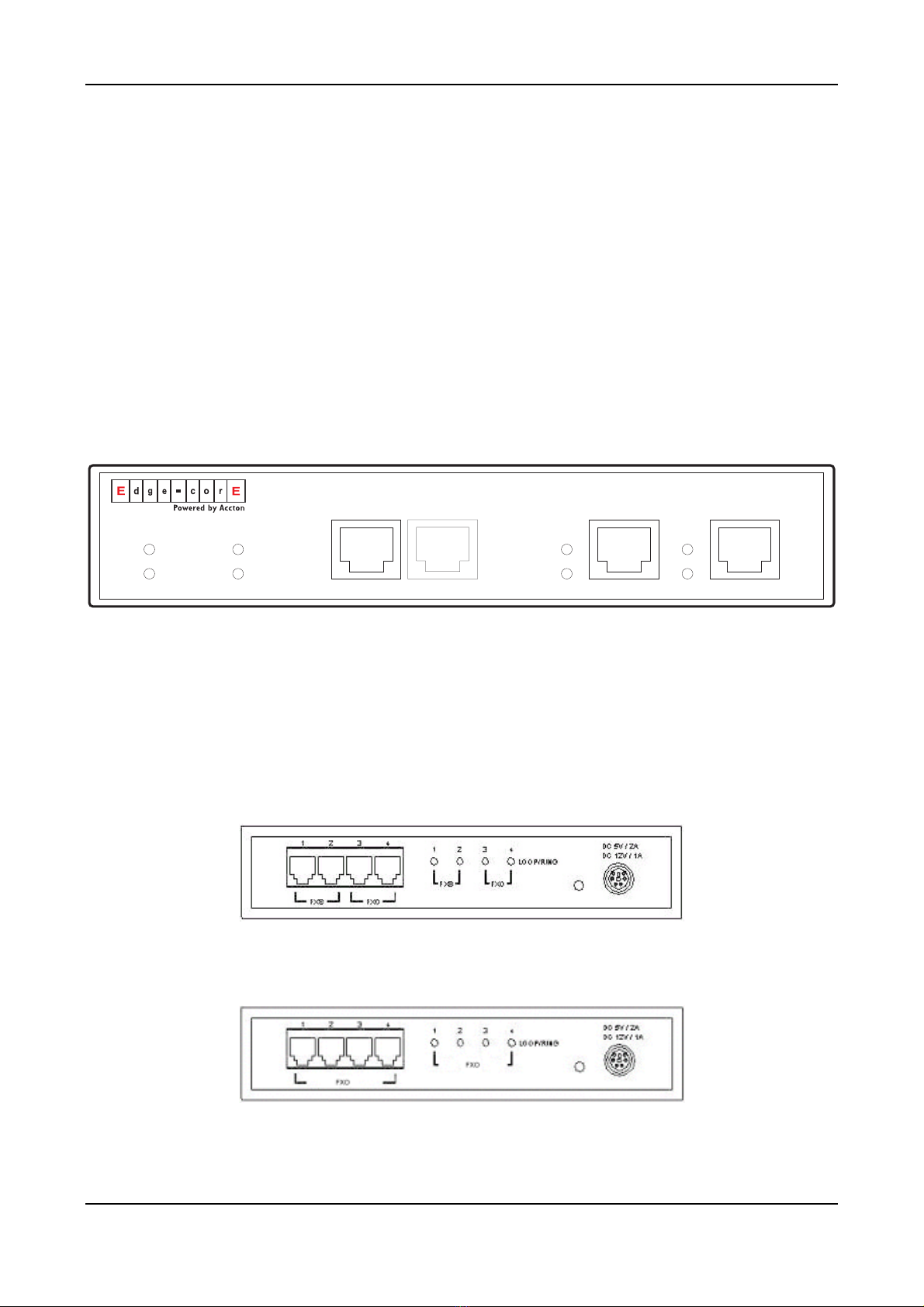
5.1. PANEL .................................................................................................................................................8
5.2. LED INDICATOR ...................................................................................................................................9
5.3. CONNECTORS ....................................................................................................................................10
6. BASIC INSTALLATION AND CONFIGURATION......................................................................................... 11
6.1. PHONE SET CONNECTION ...................................................................................................................11
6.2. PERSONAL COMPUTER CONNECTION ...................................................................................................11
7. CONFIGURATION OF PARAMETERS FOR FUNCTION AND WEB MANAGEMENT PAGE.............. 13
7.1. STEPS FOR CONFIGURATION ...............................................................................................................13
7.2. CONFIGURATION THE BASIC PARAMETERS VIA WEB MANAGEMENT PAGE ................................................19
7.3. CONFIGURATION OF FEATURES............................................................................................................24
8. BEHIND NAT & FIREWALL (USE PRIVATE IP) ......................................................................................... 101
9. FILE MANAGEMENT ...................................................................................................................................... 102
9.1. FILE TYPES......................................................................................................................................102
9.2. SOFTWARE UPDATE..........................................................................................................................103
10. NETWORK MANAGEMENT...................................................................................................................... 107
10.1. PASSWORD MANAGEMENT ................................................................................................................107
10.2. MANAGEMENT BY SYSTEM CONSOLE, AND TELNET..............................................................................107
10.3. MANAGEMENT BY WEB PAGE ............................................................................................................109
10.4. MANAGEMENT BY PHONE SET............................................................................................................109
11. SPECIFICATIONS ............................................................................................................................................. 113
12. REGION ID TO TELECOM COUNTRY CODE ....................................................................................... 115
13. SAMPLE SHEETS FOR NUMBERING PLAN.......................................................................................... 116
1

VTG3300 Series user guide
1. Safety Instructions
1. Do not attempt to service the product yourself. Any servicing of this product should be referred to a
qualified service personnel.
2. To avoid electric shock, do not put your finger, pin, wire, or any other metal objects into vents and gaps.
3. To avoid accidental fire or electric shock, do not twist power cord or place it under heavy objects.
4. The product should be connected to a power supply of the type described in the operating instructions or
as marked on the product.
5. To avoid hazard to children, dispose of the product’s plastic packaging carefully.
6. The phone line from PSTN Operator should always be connected to the LINE or FXO connector. It should
not be connected to the PHONE/FAX or FXS connector as it may cause damage to the product.
7. Please read all the instructions before using this product.
3

2. Preface
The VTG3300 series products were developed by using the latest VoIP technologies. It is not only a
commercial PBX but also a VoIP Gateway with Auto Attendant to provide full services. High quality voice
services for telephone and Fax are provided through the Internet, in addition, several value added services are
also provided. Due to the characteristics of the Internet, bills for telephone and FAX are extremely small.
With its modularized hardware design, VTG3300 is also very simple to install, easy to carry and operate.
Models :
Model Name Description
VTG3300A 4 Ports 2 FXO + 2 FXS
VTG3300C 4 Ports 4 FXO
The VTG3300 is a commercial PBX. It can operate alone or connect to another VTG3300 to create one
system and dial each other by extension number. When two sets of VTG3300 are installed in separate
locations, and both are connected to an IP network, then the extension lines of each VTG3300 can dial each
other by dialing the extension number as in the same PBX.
4

VTG3300 Series user guide
3. Feature Descriptions
3.1. Basic and Advanced Features
Remote Transit Call
VTG3300 supports “Transit – In Call” and “Transit – Out Call” functions. User can access remotely.
Call Forward
VTG3300 supports “Call Forward” function. User can get the call at any location.
T.38 FAX
VTG3300 supports T.38 FAX service. Like voice services, FAX features “Call Forward” and “Follow me”
functions.
Private IP Address
VTG3300 can be connected to any VTG3300 at any location around the world just through the private IP
address behind NAT.
Life Line
Following the standard, VTG3300 keeps line alive when power outage happens.(Model with FXS port )
Network Management Capabilities
VTG3300 provides management via telephone sets (Only Trunking Gateway with FXS port), system
console, Telnet and Web Browser. Users can configure or modify the setting through any telephone set,
system console, or Telnet. System manager can browse information through a PC and manage the
system no matter where he is.
FTP Software Update
The FTP server is embedded into VTG3300. Via FTP server, software can be uploaded for updating.
3.2. PBX Features
Extension Line
The FXS ports on VTG3300 may act as extension lines. Each port can be assigned with an extension
number from 11 to 14. If you like to connect to another extension line, you can dial the extension
number directly or dial the prefix of the equipment first, followed by the extension number.
Through IP To another Extension line of VTG3300
Extension line are not limited to connect to extension lines within the same gateway, it can also connect
to extension lines of another VTG3300 via IP network by dialing the phone number of the VTG3300
followed by the extension number or by dialing the prefix.
Call Transfer
VTG3300 can transfer the call of extension line to
♦ An extension line in the same gateway
5

♦ An extension line of any remote VTG3300
Abbreviated Dial
100 Abbreviated dialing numbers can be assigned to the VTG3300. Abbreviated dialing number can
contain the numeric numbers and special character “ * “ and “ # “.The priority of the first 70 indexes of
abbreviated dialing is beyond the limitation of Barring rule.
Embedded Auto Attendant
VTG3300 provides auto attendant to any incoming call. The Greetings tone can be recorded via the
telephone set by users. Only the Trunking Gateway with FXS port supports this feature.
Operator
Any extension line of VTG3300 can be assigned as an Operator. Any incoming call will be connected to
the operator if the access code for Operator is dialed. The other extension lines which are assigned to
the operator Group can act as operator if the operator is busy. The Operator can be forwarded to :
♦ The extension line of the same gateway
♦ The extension line of a remote VTG3300 gateway
♦ Trunk Groups
"Trunk" is a general name for FXO lines that connect to PSTN. The trunks of VTG3300 can be separated
into two groups. Each FXO port will belong to one of the trunk groups.
♦ Barring set to each extension line
There are six barring classes embedded. Each extension line can be set by one of the barring class.
♦ CDR
VTG3300 provides a dedicate RS-232 port for CDR (Call Detail Record), CDR can also be recorded
through Internet for further accounting and data statistics.
3.3. Other Special Features
Remote Trunk Seizure
VTG3300 can seize the trunk groups of a remote VTG3300 gateway manually or automatically.
Softkey
Softkey can be defined on each FXS/FXO port of VTG3300 and be activated manually or automatically.
Caller ID Display
If a phone set that can display Caller-ID is connected to the extension line, the caller ID from another
FXS port will be displayed. The display format is the Prefix of incoming gateway followed by the
extension number. A Phone set with FSK standard is required.
Local Trunk Overflow
If the trunks in same gateway are not available, the extension line of VTG3300 can seize the local trunk
of another gateway that is under the same Subnet Mask.
6

VTG3300 Series user guide
4. Package Contents
1. The VTG3300 Gateway X 1
2. Power Cord X 1
3. Manual/Tools CD-ROM X 1
4. Rubber footer X 1
7

5. General Descriptions
5.1. Panel
VTG3306A/C : model with 4 ports
On the front panel you can find two Ethernet ports, a console port, LED status indicator and the port special for
CDR which can record the detailed data of the calls for accounting and statistics.
5.1.2. Front Panel
VTG3306
LAN
MDI-X
PC
IMD
Link/Act
100Mbps
Alarm
Power
Console
9600 8N1
Time server
CPU/Act
CDR
VTG3300 Front Panel
5.1.3. Rear Panel
There is a button on the rear panel of VTG3300 for special maintenance. Please don’t touch this button under
normal operation.
VTG3306A Rear Panel
VTG3306C Rear Panel
8

VTG3300 Series user guide
5.2. LED Indicator
Label LED Description
ON Network Linked UpLink/Act
FLASH Sending/Receiving data packets
ON Transmission Rate is 100Mbps
10/100 Ethernet
100Mbps
OFF Transmission Rate is 10Mbps
ON Off Hook, loop current detectedLOOP/ RING (FXS)
FLASH Ring signal sending
ON Answered, loop current detected
Port Information
LOOP/ RING
(
FXO
)
FLASH Ringing
Power ON Power supply normal
Alarm ON Errors detected when auto HW
diagnostics ran:
FXO Error detected or circuit break
ON CPU in normal operationCPU/Act
FLASH CPU is Running
ON Able to access to Time Server
FLASH Trying to access to Time Server
Device
Time Server
OFF NOT able to access to Time Server
9

5.3. Connectors
Terminal Label Description
FXS For analog phone set or FAX machine
Voice
FXO For public lines or trunk from PSTN Operator
To LAN (MDI-X) RJ-45 MDI-X terminal, for LANNetwork
To PC (MDI) RJ-45 MDI terminal, for PC
RJ-45 CONSOLE For system console
10

VTG3300 Series user guide
6. Basic Installation and Configuration
6.1. Phone Set Connection
Example : VTG3306A
6.2. Personal Computer Connection
Example : VTG3306C
There is a console port on the panel of VTG3306C. Plug the attached Console cable into the console port and
connect it with PC on the other side.
11

6.2.1. Configuration of Parameters for Console
After connecting the PC to VTG3300 via a RS-232 cable, Power on the PC and configure the PC parameters
as following:
Speed : 9600
Data Byte : 8
Parity Check : None
Stop Byte : 1
Flow Control : None
12

VTG3300 Series user guide
7. Configuration of Parameters for Function and Web
Management Page
7.1. Steps for Configuration
7.1.1. General
7.1.1.1. VTG3300
(1) Connect the Console Terminal to VTG3300 Console port by RS-232 cable.
(2) Configure the parameters of Console Terminal. Please refer to Section 6.2.1Configuration of
Parameters for Console.
(3) Set Region ID and restore to the default value. Please refer to Section 7.1.2 Configuration of
Regional ID.
(4) Configure a fixed IP address by using the System Console ( or use the default IP address
192.168.0.2) and the password (e.g. 123) to enter the Web Management Page. For security reason,
please configure the password for verification when entering the Web Management page. Refer to
Section 7.1.3 Configuration of IP and 7.1.5 for configuration Password for Web Management Page.
(5) Connect PC to the network port labeled “To PC” on VTG3300 by LAN cable. The Indicator of
LNK/ACT will be ON if the connection is working normally.
(6) Set IP address of PC to the same subnet as IP address of VTG3300. For example, the default IP
address of VTG3300 is 192.168.0.2 , then you may set 192.168.0.3 as the IP address of the PC.
(PC re-start may be required).
(7) Run the Broswer, enter the IP address of VTG3300 and then press ENTER key.
(8) In the window , USER ID and PASSWORD will be prompted. Enter “WEB” (all capital letter) as
USER ID and the password you configured (e.g. 123), press ENTER key. Now you are entering
the Home page of the Web Management page.
(9) On the Web Management Page, set the Region ID, Area Code, Phone Number, UDP port and other
features. Please refer to Section 7.2.1 Configuration of Phone Number via Web Management.
(10) If you like to use DHCP or PPPoE services, you may set the parameters from Web Management
Page or via Console terminal and restart VTG3300. Please be noted, new dynamic IP address will
be applied after restarting. It causes the problem to enter the original Web Management Page. You
have to check the new IP address from the Console terminal and enter the Web Management page
by this new IP address.
(11) When all of the parameters had been configured, connect VTG3300 to Internet. The system will
start after the indicator Time Server turns ON.
13

7.1.2. Configuration of Regional ID
The default value of VTG3300 series product is dependent on the location of purchase order. Please check if
the Region ID is for the country where VTG3300 will be operated. From the label located at the bottom of the
box, you may find the default value of Region ID, for example, “43”, the Region ID of Taiwan, is set as default
value. If the Region ID is correct, skip to the next step, otherwise change the Region ID. Please refer the
Section 12 Region ID to Telecom Country code.
The Instructions below showing how to set Region ID from Console terminal; using Telnet can also follow the
same instructions.
(In the example, the Region ID is changed to 07 for China)
Voice Gateway>enable
Voice Gateway #configure
Enter configuration commands, one per line. End with CNTL/Z
Voice Gateway (config)#regional_id 07
Voice Gateway (config)#exit
Voice Gateway #delete nvram
This command resets the system to factory defaults
All system parameters will restore to their default factory settings. All static and dynamic addresses will be
removed.
Reset system with factory defaults, [Y]es or [N]o? Yes
Attention :
1. After Changing the Region ID, the system has to be reset to the default value. Therefore this step should
be done first.
2. In case the IP address is being set, the following instruction may keep the IP address unchanged after
reset :
“delete nvram keep_ip”
7.1.3. Configuration of IP
An IP Address is required for the VTG3300 series product. How to get the IP address depends on the network
configuration to which the gateway will be connected. Please refer the following table for the network
configuration and define the IP address before doing system configuration. If fixed IP address will be used,
you have to apply for Internet service from Internet Service Provider (ISP) to get an available IP address.
DHCP, which is not recommended, or PPPoE, which is provided by most of ADSL ISP, may be used for this
gateway. In the following table, please find the information required for different network configurations.
14

VTG3300 Series user guide
IP Network Configuration Information Required
Public IP address IP address
Subnet mask
Default Gateway
Notes: Usually the IP address is assigned by the ISP to
avoid conflict with the other equipment.
Fixed IP Address
Private IP address IP address
Subnet mask
Default Gateway
Notes: IP Sharing is required for private IP address. In
the IP Sharing environment, IP address of VTG3300
has to be set as a virtual Server
DHCP Please contact your MIS personnel. Using DHCP is not
recommended
PPPoE
(Applied to most ADSL service)
Account Number
Password
Notes: Information is assigned by the ISP, please
contact your ISP if you don’t know or you forget the
account number.
You may perform the IP setting via System Console, then enter the Web Management page to perform the
other settings.
7.1.3.1. Configuration of IP Address via System Console
Configuration via System Console
(In this example)
IP will be 10.13.6.21、
Subnet mask is 255.255.255.0、
Default Gateway is 10.13.6.130)
Voice Gateway>enable
Voice Gateway #configure
Enter configuration commands, one per line. End with CNTL/Z
15

Voice Gateway (config)#ip state user
Voice Gateway (config)#ip address 10.13.6.21 255.255.255.0
System need to restart
Voice Gateway (config)#ip default-gateway 10.13.6.130
Voice Gateway (config)#exit
Voice Gateway #restart
This command resets the system. System will restart operation code agent.
Reset system, [Y]es or [N]o? Yes
7.1.4. Modify the Configuration via Web Management Page
On VTG3300 series Web Management Page, select folder “IP SETTINGS”
16

VTG3300 Series user guideVTG3300 Series user guide
17
17

Group Field Descriptions Default Value
IP State The type of IP Address :
Manual:User enters the assigned static IP
address
Auto(DHCP):D
y
namic IP address from DHCP
server
PPPoE:Throu
g
h PPPoE to
g
et the IP address
from ISP. Please fill in the account information
under PPPoE Settings, if PPPoE is selected.
Manual
Current Setting Display the current setting: IP information,
including IP Address, Subnet Mask and Default
Gateway. (Display only)
192.168.0.2
255.255.255.0
192.168.0.1
IP Settings
Change To Enter the information to be updated :
1. IP Address
2. Subnet Mask
3. Default Gateway
(IP State must be set to “Manual”)
After you have filled out these parameters, click
“Apply” button to activate the updated values.
Then Warm Start the system.
Account PPPoE account, provided by ISP Blank
Password PPPoE password of account Blank
Confirm Password PPPoE password reconfirmed Blank
PPPoE
Settings
Service Name Service Name of PPPoE account, provided by
ISP. At this moment, it is not required for most of
ISP, only a few exceptions.
Blank
Primary Address IP Address of the Primary DNS server. The
default value is configured in advance,
depending on the region of shipment.
168.95.1.1 is default for Taiwan region.
168.95.1.1DNS
Server
Secondary Address IP Address of the Secondary DNS server. Blank
18
Table of contents
Popular Gateway manuals by other brands

SSV
SSV RMG/941 Series Hardware reference

D-Link
D-Link DVX-3500 Quick installation guide

Bosch
Bosch MB LAN 2 installation instructions

Gira
Gira 2111 00 operating instructions

ZyXEL Communications
ZyXEL Communications P-660HN-T1H Specifications

KSH International
KSH International WPC-832-2-Modbus-MQTT user manual