9
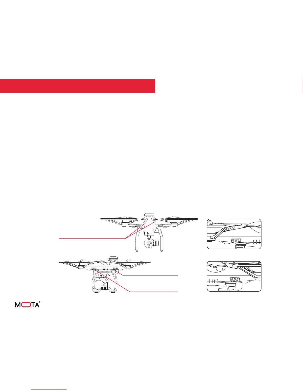
FLIGHT READINESS INDICATORS
These indicators give you vital information about flight
readiness status.
Treat them as a go / no go for flight.
Do not attempt a take-off if they do not show that the drone is
ready for flight.
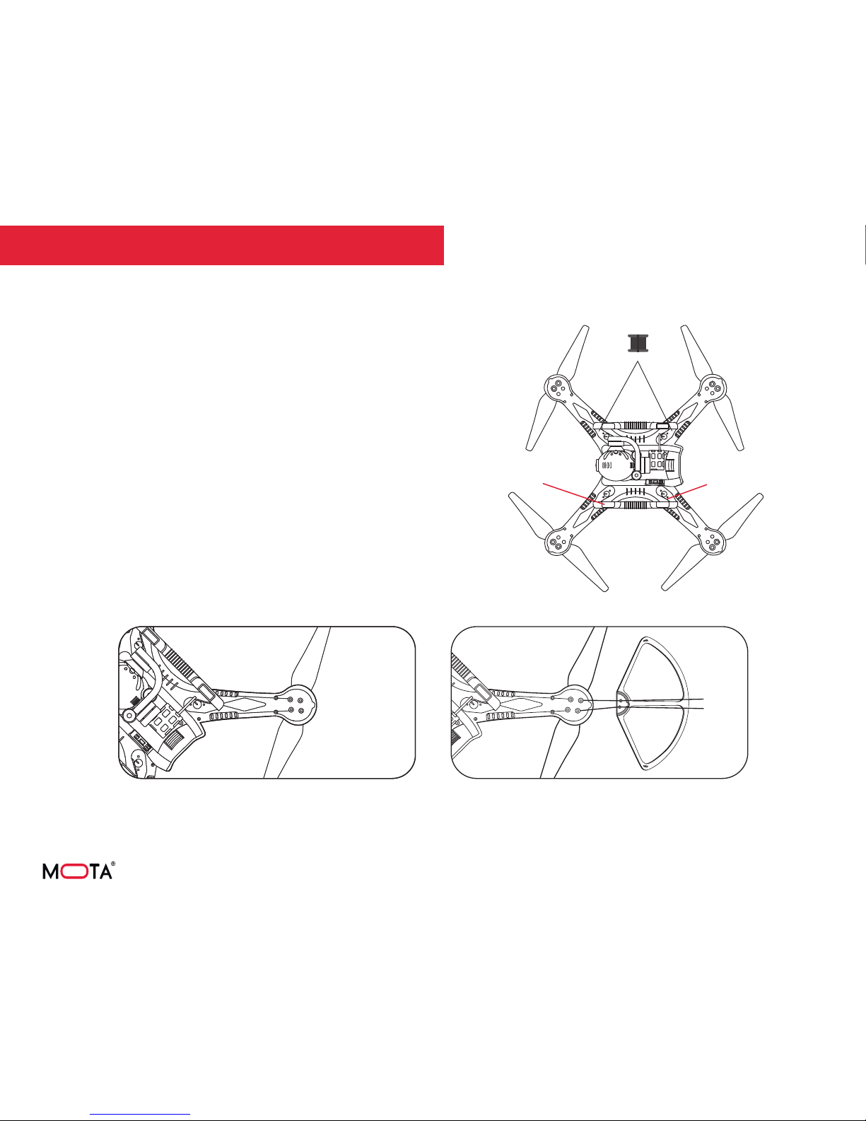
Receiver Decoding Indicator (white)
Front-bottom indicators (red)
Back-bottom indicators (green)
Back-bottom indicators (green)
Front-bottom indicators (red)
Controller Signal Strength (White)
The white bars on the drone illuminate steadily when controller
signal strength is within specification.
The white bars flash rapidly or slowly when controller signal
strength is not within specification.
Critical Battery Level (Red and Green)
If battery voltage reaches critical level, or less than about
10.4 V, the red and green bars will flash slowly and the Critical
Battery Level Alarm will sound.
Motor Unlocking (Red)
The red bars on the drone illuminate steadily once the motors
are unlocked. They will fash quickly when the motor is locked.
Motors must be unlocked
GPS Signal Strength and Critical Battery Level (Green)
The green bars on the drone illuminate steadily when GPS
signal strength is within specification.
If GPS signal strength is not within specification, the green
indicators will flash.
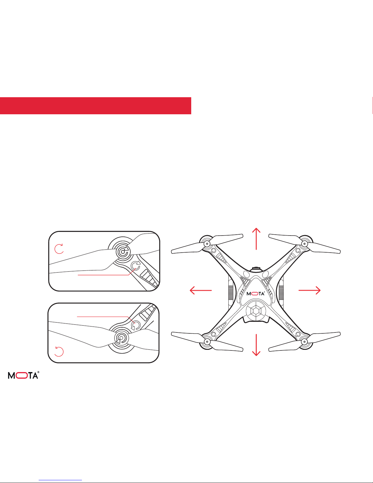
LED Indicators