Moteurs Baudouin WEIFU ECU56 Specification sheet

DPK-MAN-EN-0000-0002-18-08-13
Moteurs Baudouin reserve the right to modify these specifications, without notice.
Document not contractual.
WEIFU ECU56 ELECTRONIC GOVERNOR
Date :
13-08-18
PowerKit Engine
Page :
1 / 14
Baudouin.com
Technoparc du Brégadan - 13260 Cassis / France –Tel. +33 488 688 500
WEIFU ECU56
ELECTRONIC GOVERNOR
Use & maintenance manual
Document Courtesy of Fly Parts Guy Co.
www.FlyPartsGuy.com
Document Courtesy of Fly Parts Guy Co.
www.FlyPartsGuy.com

DPK-MAN-EN-0000-0002-18-08-13
Moteurs Baudouin reserve the right to modify these specifications, without notice.
Document not contractual.
WEIFU ECU56 ELECTRONIC GOVERNOR
Date :
13-08-18
PowerKit Engine
Page :
2 / 14
Baudouin.com
Technoparc du Brégadan - 13260 Cassis / France –Tel. +33 488 688 500
INDEX
1Preface .................................................................................................................3
2Warning .................................................................................................................3
3Working principle .................................................................................................................3
4System composition .................................................................................................................4
4.1 Speed governor Weifu ECU56 ..............................................................................................4
4.2 Actuator .................................................................................................................5
4.3 Speed sensor .................................................................................................................5
5Installation and commissioning .......................................................................................................6
5.1 Installation .................................................................................................................6
5.2 Commissioning .................................................................................................................9
6Parallel function setting ...............................................................................................................11
7Fault diagnosis and treatment ......................................................................................................12
Document Courtesy of Fly Parts Guy Co.
www.FlyPartsGuy.com
Document Courtesy of Fly Parts Guy Co.
www.FlyPartsGuy.com

DPK-MAN-EN-0000-0002-18-08-13
Moteurs Baudouin reserve the right to modify these specifications, without notice.
Document not contractual.
WEIFU ECU56 ELECTRONIC GOVERNOR
Date :
13-08-18
PowerKit Engine
Page :
3 / 14
Baudouin.com
Technoparc du Brégadan - 13260 Cassis / France –Tel. +33 488 688 500
1 Preface
This manual mainly introduced the working principle, composition, adjustment, operation, maintenance
and some simple fault elimination methods of the electronic speed control system.
It is applicable to the staff who have knowledge of the engines andelectronic speed control unitsand those
who do some daily installment, connecting wires, using and maintenance.
We suggest You shall put the manual in the workplace and strictly follow the methods provided here.
2 Warning
Speed sensor to the electronic control system shall not be shared with other systems, or they may cause
serious consequences.
You can't rely on the electronic speed control system to prevent engine overspeed, and overspeed
protection device installed independently, effectively in the engine system.
Before starting the engine should confirm the fuel injection pump rod in oil cut-off position, push and pull
the fuel rack should be flexible and no jam.
3 Working principle
The electronic governor is based on the working principle of the mechanical governor but electronic
governor is better than mechanical governor. The electronic governor permit to the diesel engine to have
a prominent steady state speed regulation and a good transient speed regulation performance that can
quickly and accurately respond to the change of the engine state.
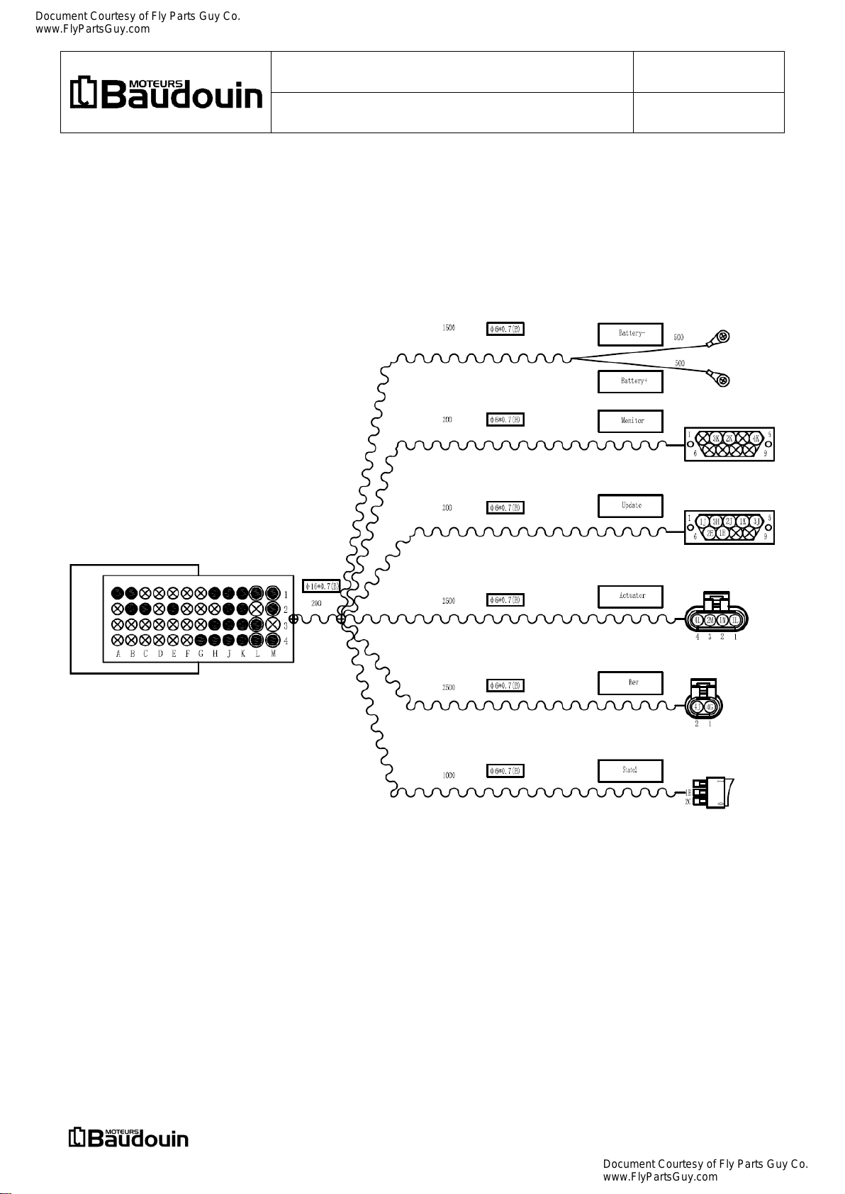
This electronic governor is a full digital control of electronic governor, the system structure diagram as
shown in the following figure.
The electronic governor collects the throttle position and the engine speed, and then sends out the
instruction of tension bar’s position to control the supply of oil pump.
In the power generation mode, the throttle device becomes a switch to control idle speed to operating
speed. Governor control the working speed by PID controller to ensure that the steady speed and the
transient speed of engine meet requirements.
Document Courtesy of Fly Parts Guy Co.
www.FlyPartsGuy.com
Document Courtesy of Fly Parts Guy Co.
www.FlyPartsGuy.com

DPK-MAN-EN-0000-0002-18-08-13
Moteurs Baudouin reserve the right to modify these specifications, without notice.
Document not contractual.
WEIFU ECU56 ELECTRONIC GOVERNOR
Date :
13-08-18
PowerKit Engine
Page :
4 / 14
Baudouin.com
Technoparc du Brégadan - 13260 Cassis / France –Tel. +33 488 688 500
4 System composition
4.1 Speed governor Weifu ECU56
4.1.1 The basic electronic characteristics
Supply Voltage : 12 Vdc (Scope 9 ~16 Vdc) or 24 Vdc (Scope 18 ~32 Vdc)
Supply consumption : ≤ 0.1 A (excluding actuator)
≤ 2.4 A with actuator
Speed fluctuation ratio : ≤ ±0.25%
The environment temperature : - 15°C ~+ 80°C
Environmental humidity : < 95%
4.1.2 Governor appearance and installation dimension
The governor should be installed in the control box.
You should try to choose the air drying, temperature suitable place to install with vertical state.
The installation dimension is shown in the following figure.
Document Courtesy of Fly Parts Guy Co.
www.FlyPartsGuy.com
Document Courtesy of Fly Parts Guy Co.
www.FlyPartsGuy.com

DPK-MAN-EN-0000-0002-18-08-13
Moteurs Baudouin reserve the right to modify these specifications, without notice.
Document not contractual.
WEIFU ECU56 ELECTRONIC GOVERNOR
Date :
13-08-18
PowerKit Engine
Page :
5 / 14
Baudouin.com
Technoparc du Brégadan - 13260 Cassis / France –Tel. +33 488 688 500
The governor appearance is shown in the following figures.
4.1.3 Governor description
The engine in the match, after a series of tests, the best calibration data was written to the governor.
When the system is running, the governor is used to control the engine according to the calibrating data
and the collected sensors signal.
If You need different engine performance, it is necessary to make a new calibration.
4.2 Actuator
The actuator is the electronic governor mechanism which controls the tension bar according to the
instruction of the governor. Actuator also has mechanical engine stop function. The actuator needs to be
installed and debugged on the fuel pump before it works. Disassembly only by the professionals.
4.3 Speed sensor (Magnetic Pick-up)
The speed sensor (Magnetic Pick-up) is passive magnetoelectric speed sensor. Rotation of gear disc
cause the change of magnetic gap, and this make induced electromotive force in the head coil.
Fix the speed sensor on the engine flywheel housing. Governor determinethe speed of engine by induction
flywheel gear number in certain time.
Warning :
The speed sensor is shown in the following figure.
Turn the speed sensor clockwise until touch addendum, and then turn the 3/4 ring counter anticlockwise
to 1 turns, lock the nut finally.
The sensor does not allow direct contact with the flywheel!
Key 22 to tighten Flexible pipe Ø 4 mm White electrical cables
Document Courtesy of Fly Parts Guy Co.
www.FlyPartsGuy.com
Document Courtesy of Fly Parts Guy Co.
www.FlyPartsGuy.com

DPK-MAN-EN-0000-0002-18-08-13
Moteurs Baudouin reserve the right to modify these specifications, without notice.
Document not contractual.
WEIFU ECU56 ELECTRONIC GOVERNOR
Date :
13-08-18
PowerKit Engine
Page :
6 / 14
Baudouin.com
Technoparc du Brégadan - 13260 Cassis / France –Tel. +33 488 688 500
5 Installation and commissioning
5.1 Installation
5.1.1 Electronic governor installation
The electronic governor actuator is connected with the pump at the factory. Just install the governor in the
control box, the speed sensor installed in the engine housing, and then use the wiring harness to connect
the rest parts.
Finally, the power supply wires with mark "Battery +"(red wire)and mark "Battery -"(black wire)on
the wiring harness connect to the anode and the cathode of 12 or 24 DC power supply (battery).
Warning :
Check the orientation of the connector before connecting it.
Improper connection may break the connector pins, resulting in product breakdown.
If connection is right, the connector buckle work.
Document Courtesy of Fly Parts Guy Co.
www.FlyPartsGuy.com
Document Courtesy of Fly Parts Guy Co.
www.FlyPartsGuy.com

DPK-MAN-EN-0000-0002-18-08-13
Moteurs Baudouin reserve the right to modify these specifications, without notice.
Document not contractual.
WEIFU ECU56 ELECTRONIC GOVERNOR
Date :
13-08-18
PowerKit Engine
Page :
7 / 14
Baudouin.com
Technoparc du Brégadan - 13260 Cassis / France –Tel. +33 488 688 500
Governor and harness connector
Connection between governor and harness
Speed sensor connector
Connection between harness and speed sensor
Harness actuator connector
Connection between harness and actuator
Document Courtesy of Fly Parts Guy Co.
www.FlyPartsGuy.com
Document Courtesy of Fly Parts Guy Co.
www.FlyPartsGuy.com

DPK-MAN-EN-0000-0002-18-08-13
Moteurs Baudouin reserve the right to modify these specifications, without notice.
Document not contractual.
WEIFU ECU56 ELECTRONIC GOVERNOR
Date :
13-08-18
PowerKit Engine
Page :
8 / 14
Baudouin.com
Technoparc du Brégadan - 13260 Cassis / France –Tel. +33 488 688 500
5.1.2 Harness switch definition
On the harness delivered with the governor there are 2 switches, state switch 1 and state switch 2, as
shown in the following figures.
State switch 1 (3 wires)
Grey
Blue
Yellow
State switch 2 (2 wires)
Yellow
Grey
Note : When the switches are in the state ‘|’, this means function number 1 in next table.
Document Courtesy of Fly Parts Guy Co.
www.FlyPartsGuy.com
Document Courtesy of Fly Parts Guy Co.
www.FlyPartsGuy.com

DPK-MAN-EN-0000-0002-18-08-13
Moteurs Baudouin reserve the right to modify these specifications, without notice.
Document not contractual.
WEIFU ECU56 ELECTRONIC GOVERNOR
Date :
13-08-18
PowerKit Engine
Page :
9 / 14
Baudouin.com
Technoparc du Brégadan - 13260 Cassis / France –Tel. +33 488 688 500
Table showing the function of setting state switches on harness
Function
number
State switch 1
(3 wires)
position
State switch 2
(2 wires)
position
Functional description
1
|
(blue wire
connect to yellow
wire)
|
(yellow wire
connect to grey
wire)
In this case, the engine starts normally and will be at the
idle speed after starting.
2
O
(blue wire
connect to grey
wire)
|
(yellow wire
connect to grey
wire)
3
|
(blue wire
connect to yellow
wire)
O
(yellow wire
disconnect to grey
wire)
The engine will work at the target speed 1
(standard setting 1500 Rpm).
4
O
(blue wire
connect to grey
wire)
O
(yellow wire
disconnect to grey
wire)
Governor is in power and the engine is not started, this
is a state with function mode which is to adjusting
advance angle. There is a speed protection function in
this state.
The engine is in normal mode.
This will make the engine work in the target speed 2
(standard setting 1800 Rpm).
Warning : Check the engine advance angle in advance mode function, governor must power off, the
harness state switch must be adjusted to function number 1 indicated in the above table, and
then the engine can start. The engine load must be reduced to zero, then it can switch state
between the idle state and the working state.
Note : Part of the customer's engine harness has onlystate switch 2, the state switch connect
two wires. This state switch is still only used for switching idle speed and working
speed, just without two working speed. At this point the adjustment of the target
working speed deviation only corresponding to the following knob potentiometer 4.
5.2 Commissioning
5.1.2 Function module operation
The device and corresponding functions in governor adjustment window are listed below.
Part of the function and adjustment range will be adjusted based on the engine model and the customer
requirements.
Knob potentiometer is used to change the engine related work parameters, adjustment of knob
potentiometer is carried out during the engine working.
Adjustment of governor parameters setting switch is mainly to change the working mode.
The governor parameter setting switch needs to be adjusted before governor power on, otherwise the
governor does not respond to the adjustment.
Document Courtesy of Fly Parts Guy Co.
www.FlyPartsGuy.com
Document Courtesy of Fly Parts Guy Co.
www.FlyPartsGuy.com

DPK-MAN-EN-0000-0002-18-08-13
Moteurs Baudouin reserve the right to modify these specifications, without notice.
Document not contractual.
WEIFU ECU56 ELECTRONIC GOVERNOR
Date :
13-08-18
PowerKit Engine
Page :
10 / 14
Baudouin.com
Technoparc du Brégadan - 13260 Cassis / France –Tel. +33 488 688 500
1) Adjusting region
Governor Weifu ECU56 has 8 potentiometers and 2 dial switches as indicated in the following figure.
Potentiometers and dial switches photo
Potentiometers and dial switches drawing
The 8 potentiometers and 2 dial switches are all named as indicated in the following table.
Potentiometer 1
Potentiometer 4
Potentiometer 7
Potentiometer 2
Potentiometer 5
Potentiometer 8
Potentiometer 3
Potentiometer 6
Dial switch 1
Dial switch 2
2) The definition and operation of the state switch
Device name
Function definition
Operating characteristics
Dial
switch
1
Channel
1
Adjusting advance angle mode
indication
0 Regular work
1 The advance angle mode
Channel
2
Parallel engine function allows
indication
0 Not parallel engine mode
1 Parallel engine mode
Channel
3
Signal direction of parallel
Engine indication
0 Signals of parallel engine with same change
direction
1 Signals of parallel engine with opposite
change direction
Dial
switch
2
Channel
1
Actuator direction indication G
0 The actuator rotates clockwise to increase
the amount of fuel
1 The actuator rotates counterclockwise to
increase the amount of fuel
Channel
2
The actuator arm parameter
indication
0 0 Actuator rocker arm is 9 mm
0 1 Actuator rocker arm is 12 mm
Channel
3
1 0 Actuator rocker arm is 16 mm.
1 1 Remain
Note : 0 logic is defined as OFF position of the governor parameter setting switch
1 logic is defined as ON position of the governor parameter setting switch
The above dial switches photo shows the controller parameter setting switches are in the "0" state
The position of the switch shall be determined as required before the engine test run.
Document Courtesy of Fly Parts Guy Co.
www.FlyPartsGuy.com
Document Courtesy of Fly Parts Guy Co.
www.FlyPartsGuy.com

DPK-MAN-EN-0000-0002-18-08-13
Moteurs Baudouin reserve the right to modify these specifications, without notice.
Document not contractual.
WEIFU ECU56 ELECTRONIC GOVERNOR
Date :
13-08-18
PowerKit Engine
Page :
11 / 14
Baudouin.com
Technoparc du Brégadan - 13260 Cassis / France –Tel. +33 488 688 500
3) The definition and operation of the knob type potentiometer
Device name
Function definition
Operating characteristics
The range of
parameters
Potentiometer
1
Adjust the amount of fuel to
start (starting fuel)
Clockwise rotation to increase
Counterclockwise rotation to
decreases
± 100 step
Potentiometer
2
Adjust the idle speed
Clockwise rotation to increase
Counterclockwise rotation to
decreases
± 100 Rpm
Potentiometer
3
Adjust the speed of
switching speed (time from
idle to rated speed)
Clockwise rotation to increase
Counterclockwise rotation to
decreases
± 10 Sec
Potentiometer
4
Adjust the first working
speed (target speed 1)
Clockwise rotation to increase
Counterclockwise rotation to
decreases
± 100 Rpm
Potentiometer
5
Adjust the max-load at the
first working speed (target
speed 1)
Clockwise rotation to increase
Counterclockwise rotation to
decreases
± 100 step
Potentiometer
6
Adjust the speed of
response to load changes
Clockwise rotation to increase
Counterclockwise rotation to
decreases
± 3 Sec
Potentiometer
7
Adjust the second working
speed (target speed 2)
Clockwise rotation to increase
Counterclockwise rotation to
decreases
± 100 Rpm
Potentiometer
8
Adjust the max-load at the
second working speed
(target speed 2)
Clockwise rotation to increase
Counterclockwise rotation to
decreases
± 100 step
Note : The range of parameters maybe change according to different engines.
6 Parallel function setting
The electronic governor system can meet the needs of parallel engine. Before the system is powered on,
second switch of dial switch 1 was switched to “on” side, then system responds to the control signal of the
controller unit. The dial switch 1 is used for controller parameters setting. The signal reference voltage is
+2V, up and down the reference voltage is 1V. When the signal is higher than 2V, the engine speed will
be higher than the setting working speed, when the signal is lower than 2V, the engine speed will be lower
than the set working speed.
If the system needs to achieve the reverse relationship between the voltage and speed, third switch of dial
switch 1 was switched to “on” side. At this time, this realize the function than voltage is increased and
speed is reduced, or voltage is reduced and speed is increased.
On the connection of harness, it is necessary to connect the parallel function signal wires of harness to
the unit controller. Parallel function wire is independent two wires. Yellow wire access to signal which
reference voltage is 2V. Grey wire access GND. If the signal wire needs a larger extend, the two core
shielded wire should be used, and the shielding layer is connected with the unit controller’s GND.
After the connection of the wire, the dial switch is set, the system can power on. Switch to working speed
after starting engine. At this time, there may be some deviation between the operating speed and the rated
working speed. You need adjust the speed adjustment knob potentiometer to reach the set value. And
then the realization of parallel Engine work left to the unit controller automatically or manually completed.
Warning: It is forbidden to operate the switch adjustment when the engine is working normally.
Document Courtesy of Fly Parts Guy Co.
www.FlyPartsGuy.com
Document Courtesy of Fly Parts Guy Co.
www.FlyPartsGuy.com

DPK-MAN-EN-0000-0002-18-08-13
Moteurs Baudouin reserve the right to modify these specifications, without notice.
Document not contractual.
WEIFU ECU56 ELECTRONIC GOVERNOR
Date :
13-08-18
PowerKit Engine
Page :
12 / 14
Baudouin.com
Technoparc du Brégadan - 13260 Cassis / France –Tel. +33 488 688 500
7 Fault diagnosis and treatment
Phenomenon
Detailed description
of phenomenon
Method of inspection or
cause of damage
Solution
The engine
can’t work
When the engine start
switch is turned on,
the motor is not
started to drive
Check the battery is ok.
Check battery connection is
ok.
Replace battery; connect again
according to the requirements
When the engine is
started, the engine
start speed is low or
sometimes shutdown
Check whether the battery
voltage is low when working
Replace the battery
The engine start
speed is normal, but
the exhaust pipe has
no smoke or no
burned fuel smell
The fuel injection system is
abnormal
Check fuel injection system
The engine start
speed is normal, but
the exhaust pipe has
no smoke or no oil
smell
Check whether the power
supply meets the
requirements, whether there
is bad contact or a high
volta
g
e access.
Reconnect the harness. If it is not
activated, replace governor
Check the speed sensor
installation is correct, if the
installation is correct, check
whether the speed sensor
output signal when starting
motor is working
If no signal output, replace the
speed sensor
Check the connection of
harness is ok or not. Check
whether is there
unreasonable arrangement
of harness, result in system
interference
Replace wiring harness and
eliminate interference
Check whether the actuator
is stuck or not flexible
Replace actuator
Check the tension bar of oil
pump is stuck or not
Oil pump repair or replacement
Document Courtesy of Fly Parts Guy Co.
www.FlyPartsGuy.com
Document Courtesy of Fly Parts Guy Co.
www.FlyPartsGuy.com

DPK-MAN-EN-0000-0002-18-08-13
Moteurs Baudouin reserve the right to modify these specifications, without notice.
Document not contractual.
WEIFU ECU56 ELECTRONIC GOVERNOR
Date :
13-08-18
PowerKit Engine
Page :
13 / 14
Baudouin.com
Technoparc du Brégadan - 13260 Cassis / France –Tel. +33 488 688 500
Phenomenon
Detailed description
of phenomenon
Method of inspection or
cause of damage
Solution
Engine
speed
instability
The fuel injection
system is abnormal
Remove the actuator, check
whether tension bar is
flexible, and whether
actuator is stuck
Replace actuator if actuator is not
flexible.
If the rod is stuck, repair the fuel
pump or replace it
Detect theuniformityof each
cylinder supply of oil pump.
And check whether the
injector atomization is
normal.
Need to recalibrate the oil pump or
replace the injector
Check connection of state
switch and harness is
connected well
Replace harness
Governor data error
Replace governor
Black smoke from
engine exhaust pipe
and other abnormal
phenomena
Check engine intake system
and exhaust system
If there is a blockage or other
abnormalities, please do treatment
in time
Cannot see other
anomalies from the
phenomenon
Check whether the control
system is in a strong
interference environment
Strengthen shielding measures
The fuel system is abnormal
Need to further check the fuel
injection system
After the
engine is
started,
there is no
idle time to
switch to
the working
speed
No alarm display on
the genset control
screen
Check the setting of speed
switch parameter which
make the engine switch
working speed form idle
speed
Reset genset control parameters
Idle alarm display on
the genset control
screen
Check whether the state
switch 2 is in poor contact or
other damage
Replace the status switch or
replace the whole wiring harness
Governor data mismatch or
damage
Replace the governor
Engine idle
speed
cannot
switch to
working
speed
No alarm display on
the genset control
screen
Check the setting of speed
switch parameter which
make the engine switch
working speed form idle
speed
Reset genset control parameters
Idle alarm display on
the genset control
screen
Check whether the state
switch 2 is in poor contact or
other damage
Replace the status switch or
replace the whole wiring harness
Governor data mismatch or
damage
Replace the governor
Document Courtesy of Fly Parts Guy Co.
www.FlyPartsGuy.com
Document Courtesy of Fly Parts Guy Co.
www.FlyPartsGuy.com

DPK-MAN-EN-0000-0002-18-08-13
Moteurs Baudouin reserve the right to modify these specifications, without notice.
Document not contractual.
WEIFU ECU56 ELECTRONIC GOVERNOR
Date :
13-08-18
PowerKit Engine
Page :
14 / 14
Baudouin.com
Technoparc du Brégadan - 13260 Cassis / France –Tel. +33 488 688 500
Phenomenon
Detailed description
of phenomenon
Method of inspection or
cause of damage
Solution
When
working at
rated
speed, the
speed of
the
machine
suddenly
drops or
even stops
Genset control
screen display power
value has exceeded
the rated power
The engine cannot
withstand the current load
Reduce the load applied on the
genset or replace the genset with
a bigger one.
Multiple start, the
engine is not working
Check the connection of
electronic governor, and
whether the power supply
shutdown sometime
Connect the connector again
according to requirements
Restart the engine, it
cannot work
Reference engine cannot
start
Reference engine cannot start
Unable to
stop
No alarm of unable to
stop display on
genset control screen
Check the genset controller
parameter settings
Reset genset controller
parameters
The alarm of unable
to stop display on
screen of the genset
controller
Check whether the power
supply wire is disconnected
Connect the power supply again,
make sure the genset can stop
Engine
overspeed
Turn off the power of
the electronic
governor, then the
genset stop
Electronic governor data
failure
Replace the governor
Turn off the power
supply of the
electronic governor,
then the genset still
working.
Mechanical stop
handle can stop
genset
Electronic governor actuator
failure
Replace actuator
Turn off the power
supply of the
electronic governor,
then the genset still
working.
Mechanical stop
handle cannot move
Plunger couple jam
Need emergency shutdown
measures, replace fuel pump
Document Courtesy of Fly Parts Guy Co.
www.FlyPartsGuy.com
Document Courtesy of Fly Parts Guy Co.
www.FlyPartsGuy.com
Table of contents
Other Moteurs Baudouin Industrial Equipment manuals
Popular Industrial Equipment manuals by other brands

SUHNER MACHINING
SUHNER MACHINING GEM 12 Technical document

Timken
Timken ROLLON ELM Series Use and maintenance

Emerson
Emerson Penberthy N2 Series Installation, operation and maintenance instructions

Nederman
Nederman NEX D 2m user manual

Daikin
Daikin ECONMQ12P-8-1K installation manual

ROBEL
ROBEL 22.38/02 operating instructions