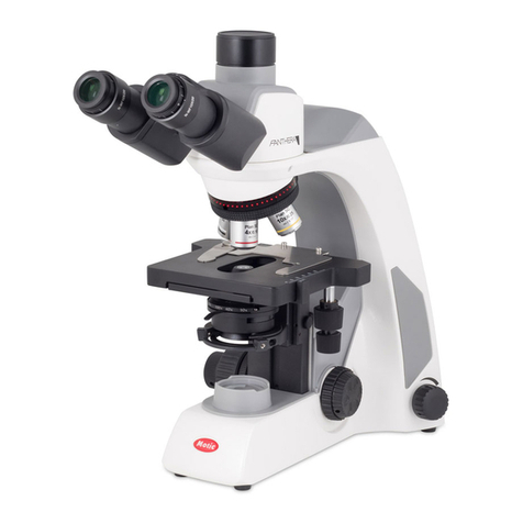
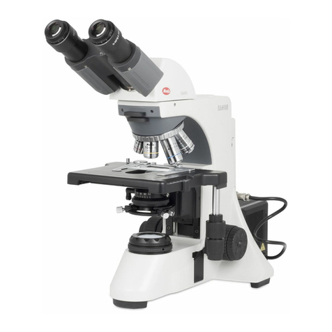
Motic BA310 Pol User manual

1
Polarizing Microscope
BA310 POL
Instructions

1
We are constantly endeavouring to improve our instruments and to adapt them to
the requirements of modern research techniques and testing methods. This involves
modification to the mechanical structure and optical design of our instruments.
Therefore, all descriptions and illustrations in this instruction manual, including all
specifications are subject to change without notice.

2
Although every effort has been made to ensure the accuracy of this instruction
manual, if you note any points that are unclear or inaccurate, please contact Motic
agency or our Technical Service directly.

3
Introduction
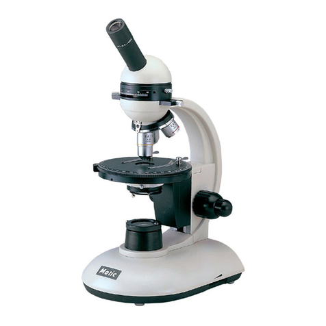
The polarizing microscope, or the petographic microscope, as it may be called, is
used to the exclusion of models in the study of thin sections of minerals and rocks.
The optical system is similar to that of the modern compound microscope.
The polarizing microscope however, contains several additional features, which
greatly increase its range of usefulness. The most distinctive features are the
graduated circular rotating stage, the polarizer and analyzer. Additionally,
accessories such as the Bertrand lens, mica plate, gypsum plate and quartz wedge
permit the evaluation of properties and characteristics that cannot be measured by
other means.

4
TABLE OF CONTENTS
SECTION PAGE
1NOMENCLATURE 6
2SETTING UP THE INSTRUMENT 10
3ASSEMBLING THE MICROSCOPE 10
3.1 Input Voltage............................................................................. 11
3.2 Lamp and Lamp Cover House (Replacing the Lamp) ....................... 11
3.3 Halogen Lamp............................................................................ 11
3.4 Specimen Clip............................................................................ 11
3.5 Attachable Mechanical Stage (Optional) ........................................ 11
3.6 Objectives ................................................................................. 11
3.7 Condenser................................................................................. 12
3.8 Intermediate Tube...................................................................... 12
3.9 Analyser Slider........................................................................... 12
3.10 Compensators............................................................................ 12
3.11 Eyepiece Tube ........................................................................... 12
3.12 Eyepieces.................................................................................. 13
3.13 Filters ....................................................................................... 13
3.14 Power Cord................................................................................ 13
4 MICROSCOPY 14
Manipulation of each Component
4.1. Coarse and Fine Focusing ............................................................ 14
I. Coarse Focus Torque Adjustment ....................................... 14
II. Coarse Focus Height Stopper ............................................. 14
4.2. Binocular Tube........................................................................... 15
I. Diopter Adjustment .......................................................... 15
II. Interpupillary Distance Adjustment..................................... 15
4.3 Condenser................................................................................. 16
I. Focusing And Centering .................................................... 16
II. Condenser Swing-Out Top Lens.......................................... 16
III. Condenser Aperture Diaphragm ......................................... 16
4.4. Field Diaphragm......................................................................... 17
4.5. Orientation of Polarizer and Analyzer ............................................ 17
4.6. Focusing and Centering the Bertrand Lens..................................... 18
4.7. Compensators............................................................................ 19
I. 1/4λ-Plate (E.G. Mica) ...................................................... 19
II. Λ-Plate (E.G. Gypsum)...................................................... 19
III. Quartz Wedge (0-4λ)........................................................ 19
4.8. Centering the Objectives ............................................................. 21
5
TABLE OF CONTENTS
SECTION PAGE
5USING OIL IMMERSION OBJECTIVE 22
6PHOTOMICROGRAPHIC PROCEDURE 23
7ACCESSORIES 24
8TERMINOLOGY 25
9 TROUBLESHOOTING TABLE 27
10 CARE AND MAINTENANCE 29

6
1 Nomenclature
Eyepiece
BA310 POL
Diopter Adjustment Ring
Intermediate Tube
Binocular Tube Clamp Screw
Binocular Eyepiece Tube
Analyser Rotating Dial
Analyser Clamp Screw
Intermediate Tube Clamp Screw
Analyser Slider
Revolving Nosepiece
Fine Focus Knob
Condenser Aperture Ring
condenser
Condenser Aperture Scale
Field Lens
Stage Rotation Clamp Screw
Circular Graduated Stage
Condenser Clamp Screw
Coarse Focus
Height Stopper

7
Compensator
Analyser Scale: 0
Analyser Rotating Dial
Compensator Slot
Bertrand Lens Centering Screw
Intermediate Tube

8
Interpupillary Distance Scale
Objective Centering Screws
Bertrand Centering Screw
Analyser Slider Knob
BA310 POL
Objective
Polarizer
Fine Focus Knob
Coarse Focus Knob
Coarse Focus Torque
Adjustment Ring
Bertrand Lens Turret
Bertrand Lens Focus Ring
Vernier Scale
Sub-Stage (Condenser Carrier)
Condenser Focus Knob
Objective Centering Nosepiece

9
Swing-Out Condenser
Aperture diaphragm
scale
Aperture Diaphragm Ring
Stage Clip
Field Diaphragm
Field Diaphragm Ring
Condenser Centering Screw
Condenser Top Lens Swing-Out Lever

10
2 Setting up the Instrument
Avoid placing the instrument in locations exposed to direct sunlight, dust,
vibration, high temperature and high humidity
3 Assembling the Microscope
3.1 Input Voltage
The automatic voltage selection works with a broad range of settings.
However, always use a power cord that is rated for the voltage used in
your area and that has been approved to meet local safety standards.
Using the wrong power cord could cause fire or equipment damage.
When using an extension cord, only use a power supply cord with a
protective earth (PE) wire.
In order to prevent electric shock, always turn the switch on the power
supply off before connecting the power cord.
AC Input Voltage
Power Switch
Brightness Control Knob
Rating Label

11
3.2 Lamp and Lamp Cover (Replacing the Lamp)
In order to prevent electric shock always turn the power switch off and
unplug the power cord before installing or replacing the lamp.
Place the microscope on its back and pull back the lamp cover plate.
Firmly insert the lamp into the socket pinholes until it reaches the
limit. Be careful not to tilt the lamp when mounting.
When installing the lamp, do not touch the glass surface of the lamp
with bare fingers. Doing so will cause fingerprints, grease, etc., to
burn onto the lamp surface, reducing the illumination provided by the
lamp. If the surface is contaminated, wipe it clean using lens tissue.
Close lamp cover plate and secure until it snaps into position.
3.3 Halogen Lamp
Tungsten-halogen lamps operate at very high temperatures and may
cause serious burn injuries if handled while hot.
When replacing these lamps, always allow them to cool before
removing them from the lamp socket.
Avoid handing the bulb envelope directly because fingerprints left on
the envelope will be burned into the glass, often initiating premature
lamp failure.
Manufacturers package tungsten-halogen lamps in protective plastic
bags to avoid handling problems.
Use a pair of scissors to cut the bag near the tungsten pins, insert the
lamp into its holder while it still remains in the bag.
Remove the bag, when the lamp is properly positioned in the lamp
socket.
3.4 Specimen Clip
Insert two specimen clips into the holes on the circular graduated
stage surface
3.5 Attachable Mechanical Stage (Optional)
Mount the attachable mechanical stage onto the circular graduated
stage, inserting the two positioning pins at the bottom of the
attachable mechanical stage into the pinholes on the stage surface.
Tighten the clamp screw.
3.6 Objectives
Lower the stage completely.
Screw the objectives into the revolving nosepiece starting with the
reference position so that clockwise rotation of the nosepiece brings
the next higher magnification objective into position.
Note: The BA310 Polarizing microscope allows you to center three
objective positions with a reference objective

12
3.7 Condenser
Raise the stage by turning the coarse focus knob.
Lower the sub-stage (condenser carrier) by turning the condenser
focus knob.
Insert the dovetail mount with aperture scale facing the front.
Secure with condenser clamp screw.
Turn the condenser focus knob to raise the condenser as far as it will
go.
3.8 Intermediate Tube
Loosen the intermediate tube clamp screw on the microscope arm.
Insert the round dovetail mount of the intermediate tube into the
round dovetail mount on the microscope arm by tilting it at an angle.
When fitting, insert the positioning pin on the underside of the
intermediate tube in the receiving groove on the arm.
Secure in position with clamp screw.
Given that the intermediate tube contains a built-in depolarizer, it is
not necessary to be concerned with the relationship between the
plane-polarized beam and photomicrographic devices. (See Microscope
Terminology)
3.9 Analyser Slider
Unscrew the analyser slider knob from the side of the slider. Insert
into the slot of the intermediate tube with the analyser-rotating dial
positioned on the right of the intermediate tube. Secure with slider
knob.
3.10 Compensators
Insert the compensator into the compensator slot of the intermediate
tube.
The compensator slot is oriented so that accessory plates are inserted
at 45º to the cross-lines.
3.11 Eyepiece Tube
Loosen the eyepiece tube clamp screw. Insert the round dovetail
mount of the eyepiece tube into the round dovetail mount on the
intermediate tube by tilting it at an angle. When fitting, insert the
positioning pin on the underside of the eyepiece tube in the receiving
groove of the intermediate tube.
Secure the eyepiece tube in position with the clamp screw.
Note: The binocular tube is designed to prevent a cross-line slant that
can be caused by adjusting the interpupillary distance. In addition, the
direction of polarizing light oscillation can be precisely aligned.

13
3.12 Eyepieces
Use the same magnification eyepieces for both the right and left eyes.
Place the eyepieces into the sleeves of the binocular tube.
The sleeve of the right eyepiece tube has positioning slots for either
90° and 45° orientation
Install the right eyepiece by aligning the positioning pin of the
eyepiece with positioning slot of the eyepiece sleeve.
Slide the rubber eyecup onto the grove around each of the eyepieces.
3.13 Filters
Place the filter in the filter holder located around the field lens, taking
care that dust, dirt and fingerprints do not get on the filter and the
field lens.
Filter selection:
Filter
Function
ND2 (T=50%)
For brightness adjustment in
photomicrography
ND4 (T=25%)
ND16(T=6%)
Blue Filter (Colour Balancing Filter)
For routine microscopy and
photomicrography
Green Interference (546nm)
For retardation measurement and
contrast adjustment
A diffuser is built into the base of the microscope. When removing the
diffuser from the light path, turn the diffuser engage/disengage screw
as far as it will go in the clockwise direction with a hex screwdriver.
When returning it to the light path, turn the screw in counter-
clockwise direction.
3.14 Power Cord
Connect the socket of the of the power cord to the AC inlet on the rear
of the microscope. Plug in the other end of the cord to an AC outlet
with ground conductor.

14
4Microscopy
Manipulation of Each Component
4.1 Coarse and Fine Focusing
Focusing is carried out with the coarse and fine focus knobs at the left
and right of the microscope stand.
The direction of vertical movement of the stage corresponds to the
turning direction of the focus knobs.
One rotation of the fine focus knob moves the stage 0.2mm. The
graduation on the fine focus knob is 2 microns.
Never attempt either of the following actions, since doing so will
damage the focusing mechanism:
Rotate the left and right knob while holding the other.
Turning the coarse and fine focus knobs further than their limit.
I. Coarse Focus Torque Adjustment
To increase the torque, turn the torque adjustment ring located
behind the left-hand coarse focus knob in the direction indicated by
the arrow. To reduce the torque, turn the ring in the direction
opposite to that indicated by the arrow.
II. Coarse Focus Height Stopper
The coarse focus height stopper marks the stage position at which
the specimen is in focus i.e. by restricting the movement of the
coarse focus knob.
With the specimen in focus, turn the coarse focus stopper knurled
screw clockwise until it reaches the stop.
When the coarse focus stopper is in position, the stage cannot be
raised from that position. However, the fine focus knob can move
the stage regardless of the limit but will only lower the stage.
Lower the stage by using the coarse focus knob.

15
4.2. Binocular Tube
I. Diopter Adjustment
Diopter adjustment compensates for differences in vision between
the left and right eyes. In addition to making observation through
both eyes easier, this adjustment also reduces the extent to which
focusing is lost when the objective magnification is changed. In
particular, this occurs when a low magnification objective is used.
In the case of a polarizing microscope, an eyepiece containing
cross-line is used for the right eye; the procedure for adjusting the
diopter differs from that of an ordinary microscope.
Turn the diopter adjustment ring on the right eyepiece to bring the
cross-line in the eyepiece into focus.
Next, focus on a specimen while viewing with the right eye, and
then turn the diopter adjustment ring on the left eyepiece and
bring specimen into focus.
II. Interpupillary Distance Adjustment
Before adjusting the interpupillary distance, bring a specimen into
focus using the 10x objective.
Adjust the interpupillary distance so that both the right and left
field of view become one.
This adjustment will enable the user to observe the specimen with
both eyes
Interpupillary distance scale

16
4.3 Condenser
I. Focusing and Centering
Fully open the field of view diaphragm and condenser aperture
diaphragm.
Set the specimen on the stage with the cover glass facing up.
Bring the specimen image into focus, using the 10X objective.
Close the field of view diaphragm to its minimum setting by means
of the field diaphragm ring.
Turn the condenser focus knob to bring the field diaphragm image
into focus on the specimen plane.
Adjust the condenser centering screws so that the image of the
field diaphragm appears at the center of the field of view. At this
time, stopping the field diaphragm image just short of the
maximum field of view may be convenient for centering.
Adjust and center the field diaphragm so that it is just outside the
field of view for each magnification change.
II. Condenser Swing–Out Top Lens
The top lens can be removed from the optical path by using the
swing-out lever. Swing the top lens into the optical path during
normal orthoscopic observation and conscopic observation. Swing
out for orhoscopic observation with 4X or lower magnification.
When measuring the retardation or observing the inference colour,
swing out the top lens to make the illuminating light path as
parallel as possible to the optical axis.
III. Condenser Aperture Diaphragm
In orthoscopic microscopy:
The condenser aperture diaphragm is provided for adjusting the
numerical aperture (N.A.) of the illuminating system of the
microscope. It decides the resolution of the image, contrast, depth
of focus and brightness.
Stopping down will lower the resolution and brightness, but
increase the contrast and depth of focus.
An image with appropriate contrast can be obtained with an
aperture setting that is 2/3 of the objective N.A.
To adjust the aperture diaphragm:
Adjust the condenser aperture diaphragm ring by referring to the
condenser aperture scale, or by observing the diaphragm image
visible on the exit pupil inside the eyepiece tube. Introduce the
Bertrand lens into the optical path and focus on the aperture
diaphragm at its minimum setting. Open aperture diaphragm to
2/3 fields of view.
When swinging out the top lens of the condenser for low
magnification objectives, completely open the condenser aperture
diaphragm.

17
In conoscopic microscopy:
In conoscopic microscopy, the condenser aperture diaphragm
works as a field diaphragm on the conoscopic image surface. Stop
down the aperture diaphragm so it limits the periphery of the field
of view of the conoscopic image.
4.4 Field Diaphragm
The field diaphragm determines the illuminated area on the specimen.
Rotating the field diaphragm ring changes the size of the field
diaphragm. For normal observation, the diaphragm is set slightly
larger than the field of view. If a larger than required area is
illuminated, extraneous light will enter the field of view. This will
create a flare in the image and lower the contrast.
The thickness of the glass slide must be 1.7mm or less, otherwise the
field diaphragm may not be focused on the specimen plane.
The diaphragm does not have any effect when the condenser top lens
is swung out of the optical path. Fully open the field diaphragm, as
the numerical aperture of the illuminating system will be reduced if the
diaphragm is excessively stopped down.
4.5 Orientation of Polarizer and Analyzer
Slide in the analyzer slider to remove the analyzer from the optical
path.
Focus on the specimen.
Take the specimen out of the optical path.
Slide out the analyser slider to move the analyzer into the optical path.
Set the analyser to the “0” position by loosening the analyzer clamp
screw and rotating the analyser dial (the rotation angle of the analyser
can be read in the range between 0º to 360º in increments of 0.1º by
the Vernier scale).

18
Rotate the Bertrand lens turret to “B” position and bring the Bertrand
lens in the optical path to enable the exit pupil of the objective to be
seen through the eyepiece. Rotate the polarizer so that a dark cross
image is formed on the exit pupil as shown in the figure above.
4.6 Focusing and Centering the Bertrand Lens
Rotate the Bertrand lens turret to “B” position and bring the Bertrand
lens in the optical path.
Bring 40x objective into optical path.
Adjust the Bertrand lens focus ring under the Bertrand lens turret to
focus on the image of the condenser aperture diaphragm that is
stopped down to 70 –80% of the numerical aperture of the objective.
Adjust the Bertrand lens centering screws to bring the image of the
condenser aperture to the center of the field of view.
The centering procedure is the same as that for the condenser except
that the condenser aperture diaphragm image is used instead of the
field diaphragm image.
Dark cross image is formed on
the exit pupil of the objective
Analyser rotating dial
Analyzer clamp screw

19
4.7 Compensators
All polarizing microscopes are fitted with a slot in the intermediate
tube above the nosepiece and between the polarizer and analyzer. This
is intended for insertion into the optical path of a compensator.
Compensators also referred to as retardation plates and are sections of
optically anisotropic material with plane faces which, when inserted
diagonally in the microscope between crossed polarizers, produce a
specific optical path difference of mutually perpendicular plane-
polarized light waves.
I. 1/4λ-plate - The 1/4λ-plate is called a mice plate because the
compensator plate is mostly made of mica. It has an optical path
difference in yellow light of around 140nm (yellow light has λ =
580nm, therefore 1/4λ = 580/4 = 145nm). It changes plane-polarized
light into circularly polarized light.
II. 1λ-plate (sensitive tint or first-order red) - The 1λ-plate is called
a gypsum plate of a thickness to give1λ optical path difference for
green light of 550 nm. This wavelength is therefore extinguished with
the resulting interference colour having the typical tint of the first-
order red/violet. This magenta colour is sometimes termed ‘sensitive
tint’.
III. Quartz Wedge –This device has a range of 4 orders and is commonly
employed for qualitative retardation measurements of petrographic
specimens or other birefringent materials whose retardation value falls
within the wedge limit. The quartz wedge is simplest form of
compensator where the optical path-length difference is varied by the
degree of insertion into the optical axis to match the optical path
difference of the specimen.
Bertrand Lens Turret
Bertrand Lens Focus Ring
Bertrand Lens Centering Screws
Other manuals for BA310 Pol
2
Table of contents
Other Motic Microscope manuals

Motic
Motic B1 Series User manual

Motic
Motic SMZ-140 User manual

Motic
Motic AE30-31 User manual

Motic
Motic BA310 Pol User manual

Motic
Motic M3600 Series User manual

Motic
Motic SMZ-161 Series User manual

Motic
Motic BA310 Pol User manual

Motic
Motic SILVER150 Series User manual

Motic
Motic BA310E User manual

Motic
Motic AE31E Series User manual

Motic
Motic SFC-11 Series User manual

Motic
Motic SFC-3 Series User manual

Motic
Motic ECO Series User manual

Motic
Motic D-Moticam 1080 User manual

Motic
Motic K Series User manual

Motic
Motic Panthera Series User manual

Motic
Motic B1-212 User manual

Motic
Motic PA43 User manual

Motic
Motic DM-143-FBGG Series User manual

Motic
Motic SMZ168 Series User manual