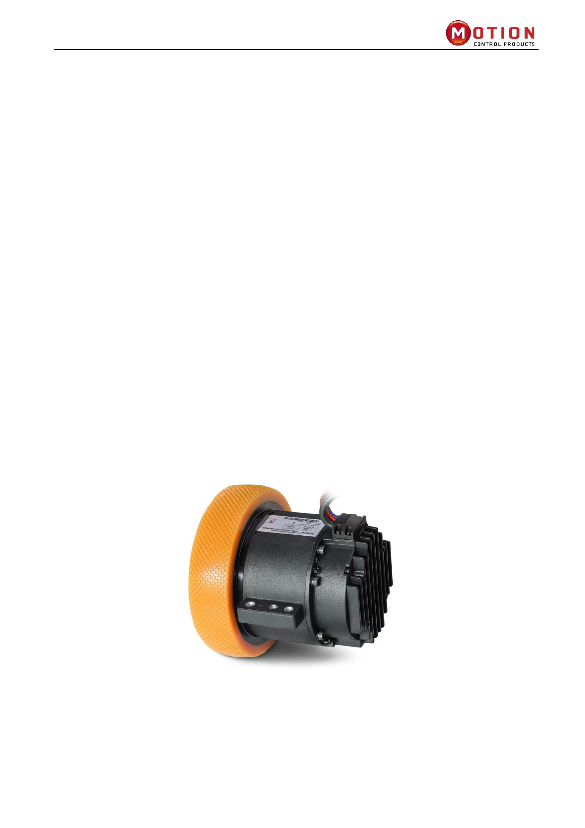
iWMC Integrated Servo Wheel User Manual
Table of Contents
PREFACE………………….................................................................................................................1
Cauons................................................................................................................................. 1
Chapter1 Model Descripon & Installaon ......................................................................... 1
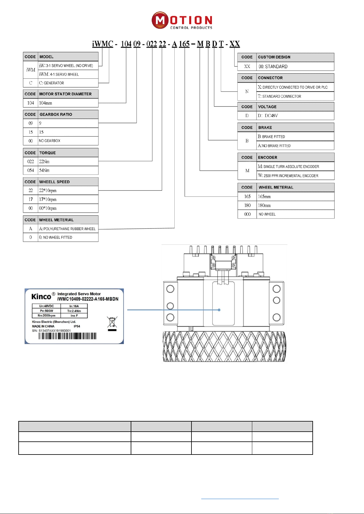
1.1 Product Introducon and Nameplate Descripon ............................................................1
1.1.1 iWMC Integrated Servo Wheel Models ..........................................................................1
1.2 iWMC Integrated Servo Wheel Installaon & Precauons.....................................................2
1.2.1 Installaon Dimension ....................................................................................................3
1.2.2 Operator Requirements...................................................................................................3
1.2.3 Electrical Requirements...................................................................................................4
1.2.4 Environment requirements .............................................................................................4
Chapter2 System Interfaces And Wiring............................................................................... 5
2.1 iWMC Servo Wheel Wiring Diagram.......................................................................................5
2.1.1 iWMC Wiring Diagram....................................................................................................5
2.1.2 Brake Resistor And Fuse Specicaons ..........................................................................5
2.2 Interface denion..................................................................................................................6
2.2.1 iWMC Integrated servo wheel with Integrated Terminals ............................................6
2.2.2 Power Supply Port ...........................................................................................................7
2.2.3 Brake Resistor Port ..........................................................................................................8
2.2.4 Terminal Specicaons ...................................................................................................8
Chapter 3 KincoServo+ Soware Introducon....................................................................... 9
3.1Fast Start ..................................................................................................................................9
3.1.1 Language Conguraon .................................................................................................9
3.1.2 Open And Save Project Files............................................................................................9
3.1.3 Start Communicaon ....................................................................................................10
3.1.4 Node ID And Baud Rate.................................................................................................10
3.1.5 Object (Add, Delete, Help) ............................................................................................11
3.2 Inialise, Save And Reboot....................................................................................................11
3.3 Load Firmware.......................................................................................................................12