Motive Power Industry Bugxter BR-150 User manual

SERVICE MANUAL
Manufactured by Motive Power Industry Co., Ltd

Content
Chapter 1 : Service notation
nSpecification
nLocking torque
Chapter 2: Engine dismantle & inspection
nEngine dismantle
nEngine inspection
nTransmission dismantle & inspection
nCarburetor adjustment
Chapter 3 : Chassis inspection
nOperation
nSteering inspection & adjustment
nBrake inspection & adjustment
nInstallation
Chapter 4 : Electric
nParts location
nCharging inspection & adjustment
nIgnition inspection
nWiring diagram

PREFACE
This manual offers all service specialists with the technological
procedures of maintenance, repairing for BR-150 show those whom may
concern how to maintain in detail, repair, change parts, troubleshoot and
reassemble, etc.
At every important section we illustrate by assembly, explosion
diagrams and photographs, if necessary, please check the diagrams
already shown.
Though we have tried our best, please kindly instruct us any
faults found in this manual.
MOTIVE POWER INDUSTRY CO., LTD.

BUGXTER SPECIFICATION
Name
BR-150
FRAME STEEL
TYPE
BR-150
SUSPENSION SYSTEM
DIMENSION FRONT SINGLE A ARM
TOTAL LENGTH
2215 mm
REAR SWING ARM
TOTAL WIDTH
1365 mm
TRANSMISSION
TOTAL HEIGHT
1480 mm
RPIMARY RATIO 1
WHEELBASE
1510 mm
SECONDARY RATIO
40/16*42/13
DRY WEIGHT 263KG CLUTCH C.V.T.
FRONT
109 KG
TIRE
REAR
154 KG
FRONT
19×7-8
TOTAL
263 KG
REAR
255/60-10
LOAD 2 PERSONS(110KG)
BRAKE SYSTEM
VEHICLT PERFORMANCE FRONT DISC BRAKE
TOP SPEED 70KM/H REAR DRUM BRAKE
FUEL CONSUMPTION 25KM/L LIGHT
CLIMBING ABILITY 25°HEAD
LIGHT(H/L) 12V-35W/35W*2
TAIL LIGHT 12V-5W
CYCLE 4BRAKING LIGHT
12V-21W
FUEL UNLEADED TURN LIGHT 12V-10W
CYLINDER NUMBER 1
ARRANGEMENT HORIZONTAL
DISPLACEMENT 150.1 cc
BORE
φ
57.5 mm
STROKE 57.8 mm
COMPRESSION RATIO 9.4 :1
MAX. POWER/RPM 7.5kw/7750rpm
AMX. TORQUE/RPM 10.2N-M/6500rpm
IDLE RPM 1700
±
100 RPM
IGNITION CDI
SPARK PLUG NGK CR7HSA
COOLING FORCE AIR & OIL
STARTER ELECTRIC
FUEL MIXING OIL PUMP
LUBRICATION SEPARATED

1.1 The operation notice:
1. Always replace gasket, Oring, cotter, pins and clip whenever reassembled.
2. When tighten screws or nuts, lock tightly as per specified locking torque, and in the sequence of
cross direction.
3. Use PGO,or PGO Recommended parts.
4. After dismantling please wash all parts necessary for checking and grease all
contact surface when reassembling.
5. Use grease recommended by P.G.O.
6.When removing battery, please dismantle the negative pole (-) first, when
assembling please connect positive pole (+) first.
6. Before installing a new fuse, confirmthe specification is correct or not.
7.After reassembling, please re-check that all connecting point, locking parts,
circuits, polar characteristics are good, before selling out.

1.2 TORQUE VALUE
1. Engine:
NO
Locking location Q’TY Thread dia. (mm) Locking torque (kg-m) Remark
1Cylinder head bolt A (intake)260.9~1.1
2Cylinder head bolt B (Exhaust) 282.2
3Cap, oil filter graze 130 1.5~2.0
4Flange nut, cam shaft base 482.2
5Fixing nut, air valve adjustment 250.7 Greasing on thread
6Guiding pin bolt, inner chain adjustment 160.9~1.1
7Oil bolt 181.7~2.0
8Fixing nut, clutch outer 112 5.0~6.0
9Nut, driven plate 112 5.0~6.0
10 Nut, driving plate 112 5.0~6.0
11 Spark plug 110 1.2~1.3
12 Nut, drive clutch 122 9.0~10.0 Left thread
13 Screw, inner chain adjuster 160.4~0.6
2.General parts please refer the following table:
NO Item Torque (kgf-m)
1 5mm bolt and nut 0.45-0.6
2 6mm bolt and nut 0.8-1.2
3 8mm bolt and nut 1.8-2.5
4 10mm bolt and nut 3.4-4.0
5 12mm bolt and nut 5.0-6.0
6 5mm screw 0.35-0.5
7 6mm screw 0.7-1.1
8 6mm flange bolt and screw 1.0-1.4
9 7mm flange bolt and screw 1.0-1.4
10 8mm flange bolt and screw 2.0-3.0
11 10mm flange bolt and screw 3.0-4.0

3.Locking Torque Standard (Chassis)
No Locking location Qty Thread dia
(mm) Kg-mRemark
1Wheel nut 16 10 6.0
2Wheel axle nut 116 8.0
3Front absorber bolt 410 6.0
4Lower suspension arm bolt 210 6.0
5Steering handle bolt 630.5
6Seat belt fixture 583.0
7Upper suspension arm 283.0
8Tie rod nut 410 5.0
9Roll cage bar 684.0
10 Rear swing arm, lower 212 6.0
11 Engine hanger with frame 210 3.5~4.5
12 Engine hanger with engine 110 3.5~4.5
13 Rear absorber 410 3.5~4.5
14 Connecting rod 483.0
15 Chain adjusting bolt, upper 112 6.0
16 Chain adjusting bolt, lower 112 6.0
17 Brake caliper fixture 682.5~3.0
18 Brake hose bolt 682.5~3.0
19 Reverse gear shaft 116 11.0
20 Rear sprocket 483.0
21 Brake disk 883.0

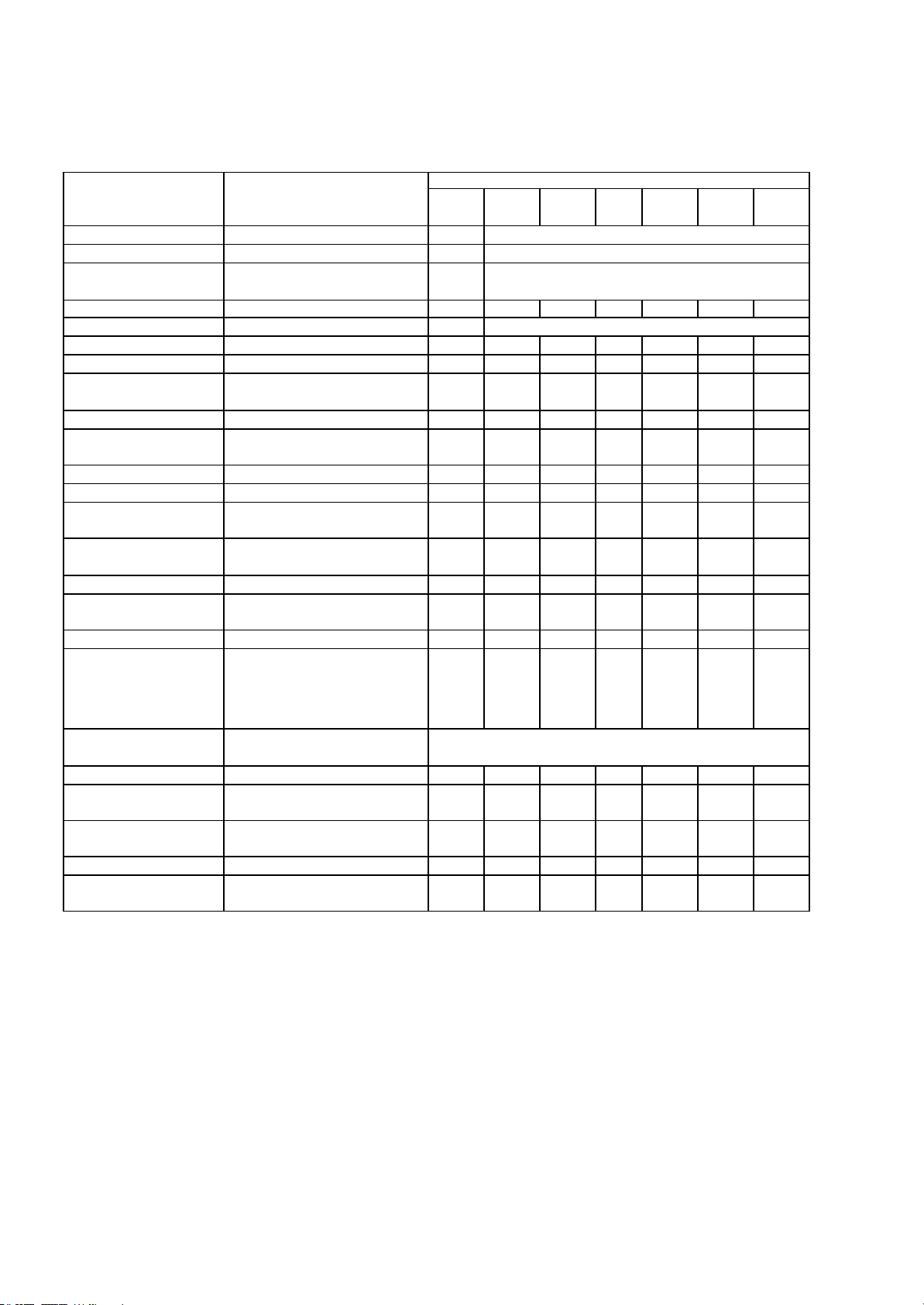
1.3 In order to achieve safe riding, good performance and reduce pollution, please execute the following
recommended maintenance table base upon average driving condition. Driving in unusual dusty
areas, require more frequent servicing. MONTHS/DISTANCE(IN KM)FOR CHECKING
Item
Checking Content 1 or
300 km 3 or
3000k 6 or
5000k 9 or
8000k
12 or
10000k 15 or
13000k 18 or
15000k
Engine oil *Replace (800cc, total 900cc) RReplace it per 1,000km
Oil Filter * Replace RReplace it per 5,000km
Coarse oil filter*(on oil
draining bolt) Clean or replace it if necessary CClean it per 3,000km or replace it if required
Oil cooler Clean or replace it if necessary ICCC
Air filter*Replace it if required Replace it per 1,000km
Gear oil *Replace (90cc, total 110 cc) RRRR
Brake performance Leaking and function check IIIIIII
Brake oil, disk, pad,
hose, master cylinder Leaking and worn-out check or
replace it if necessary IIIIIII
Clutch linings *Check or replace it if necessary IIIIII
Tires Worn-out check or replace it if
necessary IIIIII
Wheel bearing *Fasten tightly if loosen IIIIII
Driving chain *Lubricate & check the slack IIC,A,L IC,A,L IC,A,L
Chassis suspension arm,
spindle *Check looseness. Add greaseif
required IIC,A,L IC,A,L IC,A,L
Steering joint & rod *Check looseness. Adjust it if
required III
Absorber*Leaking and function check IIII
Parking Function check or replace it if
required IIIIIII
Nuts, bolts, fasteners Tighten it if required IIIIIII
Battery Make sure that the voltage
stayed over 12.8V.
Recharge the
battery it required.
Clear the poles.
IIIIIII
Valve gap *Check and adjust when engine
is cool (0.08mm for IN & EX) Adjust it when necessary
Spark plug *Clear or replace if required IIIIII
V belt *Worn out check or replace if
necessary. PPP
Fuel feeding system*Crack and blockage check.
Replace it if necessary. III
Engine idle speed *1700±100 rpm AAAAAAA
Carburetor idle A/F
Adjustment *Check and adjust referring to
CO/HC Percentage. AAAAAAA
A: adjust C: clean I: inspect, clean or replace if necessary L: lubricate R: replace
1. Items with “*” mark indicate our recommendation to have it done by PGO dealer.
2. “P” denotes that function check or replace it when the engine performance reduces significantly.
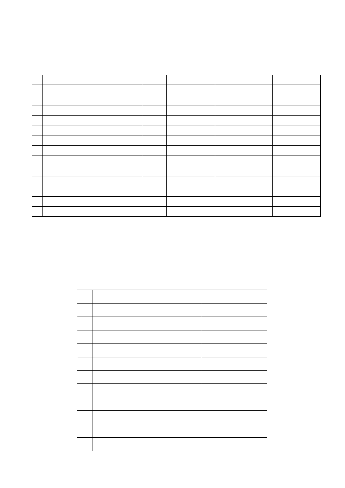
NOTE 1
:
The engine oil shall be changed completely after run-in period 300 km or one month later. This can
make sure the engine runs smoothly.
NOTE 2
:
The exchange of brake fluid
1. After disassembling of brake main cylinder or caliper, do change the new fluid.
2. Check the fluid level often, refill if necessary.
3. Change the oil seal of main cylinder and caliper every two years.
4. Change the brake fluid hose every four years.

LOCKING TORQUE 1
1
2
3
4
5
6
7
8

LOCKING TORQUE 2
910
11
12
13
14 15

LOCKING TORQUE 3
16 17
18
19
20
21

ENGINE DISMANTLE 1
Engine Dismantle
•Loosen the bolt of
connecting rod
with upper swing
arm.
Engine Dismantle
•Dismantle the nut
•Withdraw the engine
from the upper
swing arm.

ENGINE DISMANTLE 2
Engine Dismantle
•Loosen the bolt of
upper swing arm
with the lower
swing arm rear.
Engine Dismantle
•Loosen 2
bolts of
oil cooler

ENGINE DISMANTLE 3
OP of Replacing Rear Engine Hanger Collar for BR150
1. Loosen
the lock
nut.
1
OP of Replacing Rear Engine Hanger Bush for BR150
2
3
2.Dismantle the
bolt
3.Loosen the nut.
Lock torque is:
11.0 kg-m

ENGINE DISMANTLE 4
Muffler DISASSEMBLY(1)
•Loosen 2
bolts of
muffler with
cylinder head
Muffler DISASSEMBLY(2)
•Loosen 1
hexagon bolt
of muffler
with LH
cover
•Remove
muffler

ENGINE DISMANTLE 5
Air cleaner removal (1)
•Loosen 9
hexagon
flange screws
of LH cover
•Remove
engine LH
cover
Air cleaner removal (2)
•Outside end
is sponge,
clean it if
necessary
•Inside end is
paper element,
replace it if
necessary

ENGINE DISMANTLE 6
MAGNETO DISASSEMBLY(1)
•Loosen 2 hexagon
screws and 2 C-R
recess pan hd.
tapping screws
•Remove fan cover
MAGNETO DISASSEMBLY(2)
•Loosen 4 hexagon
screws of cooling
fan
•Remove cooling
fan

ENGINE DISMANTLE 7
MAGNETO DISASSEMBLY(3)
•Loosen nut of
magneto
•When installing,
tighten lock torque
is 5.5 kg-m
MAGNETO DISASSEMBLY(4)
•Pull out the
magneto with
special tool
•part no:
S620402G01A
☆tool should be
tighten lock
Table of contents
Other Motive Power Industry Motorized Toy Car manuals
Popular Motorized Toy Car manuals by other brands

Fisher-Price
Fisher-Price Power Wheels Jeep WRANGLER T1964 Owner's manual with assembly instructions

Our Generation
Our Generation Retro Cruiser quick start guide

Mini Pro
Mini Pro Chassis Dyno V2 instruction manual

Torro
Torro World of Tanks Tiger I instruction manual

Carrera
Carrera CHAMPIONS Assembly and operating instructions

DAAN Groups
DAAN Groups Voltz Toys DG80332 user manual