MotoComm DSR-1003G User manual

DSR-1003G
1
D
SR-
10 0 3
G
HELMET CAMERA & DIGITAL RECORDER SYSTEM
Thank you for purchasing the MotoComm DSR-1003G. The
DSR-1003G is designed to provide motorcycle and powersport enthusiasts
with the most complete video and audio solution at an aordable price. With
proper care and use, your DSR-1003G will provide you with years of
enjoyment. Please read the entire instruction manual before using your
DSR-1003G. If at any time you have questions regarding this product please
contact Magnum International, the manufacturer of MotoComm products.
Enjoy your DSR-1003G and ride safe.
- The MotoComm Sta
MotoComm® is a Registered Trademark of RF Limited/Magnum International.
© 2008 RF Limited/Magnum International. All Rights Reserved.

DSR-1003G 2
WARNINGS AND CAUTIONS
· In some states it is illegal to have speakers inside a helmet. Please check with your state
and local laws before using this product.
· Do not attempt to operate any controls on the DSR-1003G or other accessories while in
motion on a motorcycle or vehicle. Never take your attention away from the safe
operation of the motorcycle or vehicle or the roadway.
· The installation and mounting of the DSR-1003G should not interfere with the safe and
normal operation of the motorcycle or vehicle. Improper installations that interfere with
the operation of the motorcycle or vehicle may lead to damage of property, injury and/or
loss of life.
· Make sure to install all cables so that they remain secure whether connected together or
not. Never install a cable that is loose or hangs down from the motorcycle or vehicle, or
has the potential to hang down if it becomes disconnected.
· Do not attempt to adjust or mount the DSR-1003G camera, headset, controls, or any
other part of the system while operating a motorcycle or vehicle. Attempting to adjust or
mount any part of the DSR-1003G while operating a motorcycle orvehicle may lead to
damage of property, injury and/or loss of life.
· Do not raise the speaker volume so that it interferes with the hearing of trac and other
external noises.
· Install and operate the DSR-1003G according to the instructions. Improper installations
and use may lead to damage of property, injury and/or loss of life.
· Do not put excessive force or strain on the cables or other components of the
DSR-1003G.
· By purchasing and/or using this product you are agreeing that MotoComm and RF
Limited / Magnum International and its subsidiaries are not liable or responsible for any
accidents, property damage, injuries, or fatalities, that may or may not be caused, directly
or indirectly, by use of any of its products. If you do not accept this agreement, please
return the purchased item, unused and in new condition, to the place of purchase.
LIMITED WARRANTY
RF Limited / Magnum International warrants that this product is free from defects in
materials and workmanship under normal use and conditions for a period of one (1) year
from the date of original purchase. This warranty is limited to the original purchaser of the
product and is not transferable. Any implied warranties are limited to one (1) year. This
warranty does not cover damage which results from modication, accident, misuse, abuse,
re, ood, lightning or other acts of nature or damage resulting from repairs or alterations
performed other than by RF Limited / Magnum International. This warranty gives you
specic legal rights, and you may also have other rights, which vary, from state to state.

DSR-1003G
3
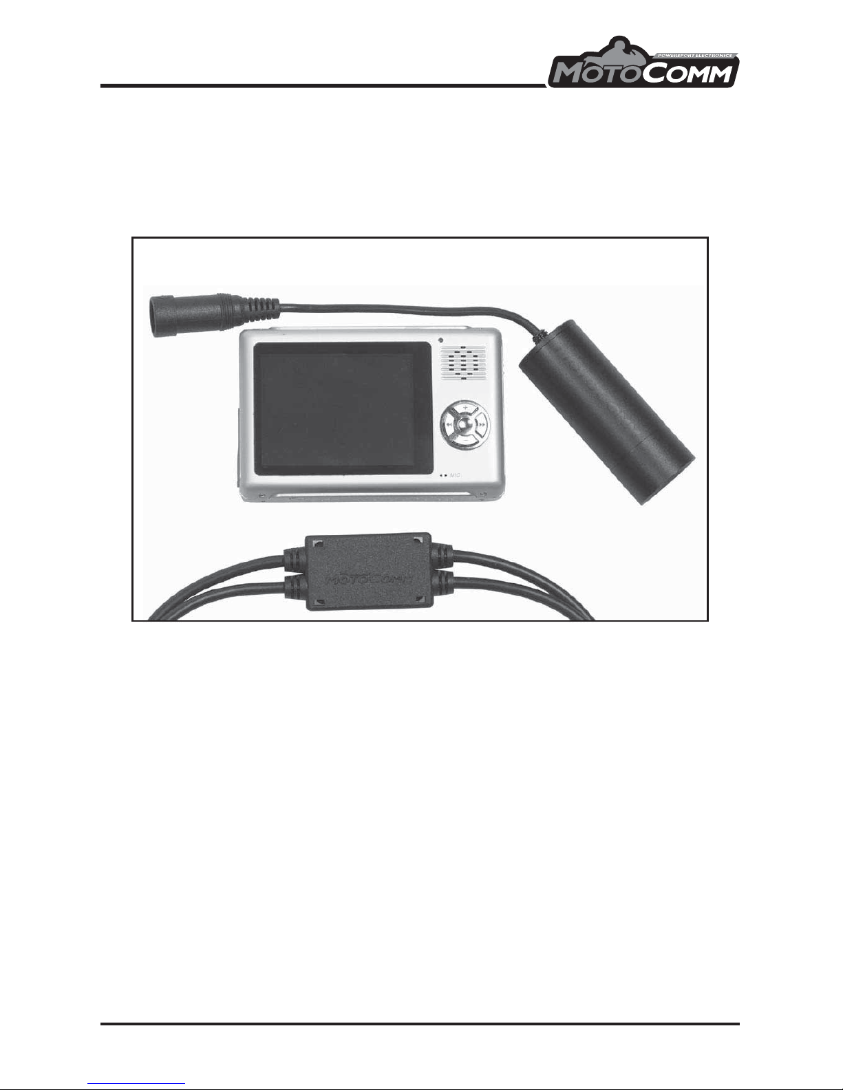
Thank you for puchasing the DSR-1003G. The DSR-1003G is a complete, all inclusive camera and
digital recorder system designed for the motorcycle/powersport rider.
Please make sure to read the entire instruction manual to get the most out of your DSR-1003G.
CONTENTS
Component / Part Number List . . . . . . . . . . . . . . . . . . . . . . . . . . . . . . . . . . . . . . . . . . . . . . . . . . . . . . . . . . . . . . 4
Battery Charging / Connectors . . . . . . . . . . . . . . . . . . . . . . . . . . . . . . . . . . . . . . . . . . . . . . . . . . . . . . . . . . . . . . 5
Quick Setup Guide . . . . . . . . . . . . . . . . . . . . . . . . . . . . . . . . . . . . . . . . . . . . . . . . . . . . . . . . . . . . . . . . . . . . . . . . . . 6
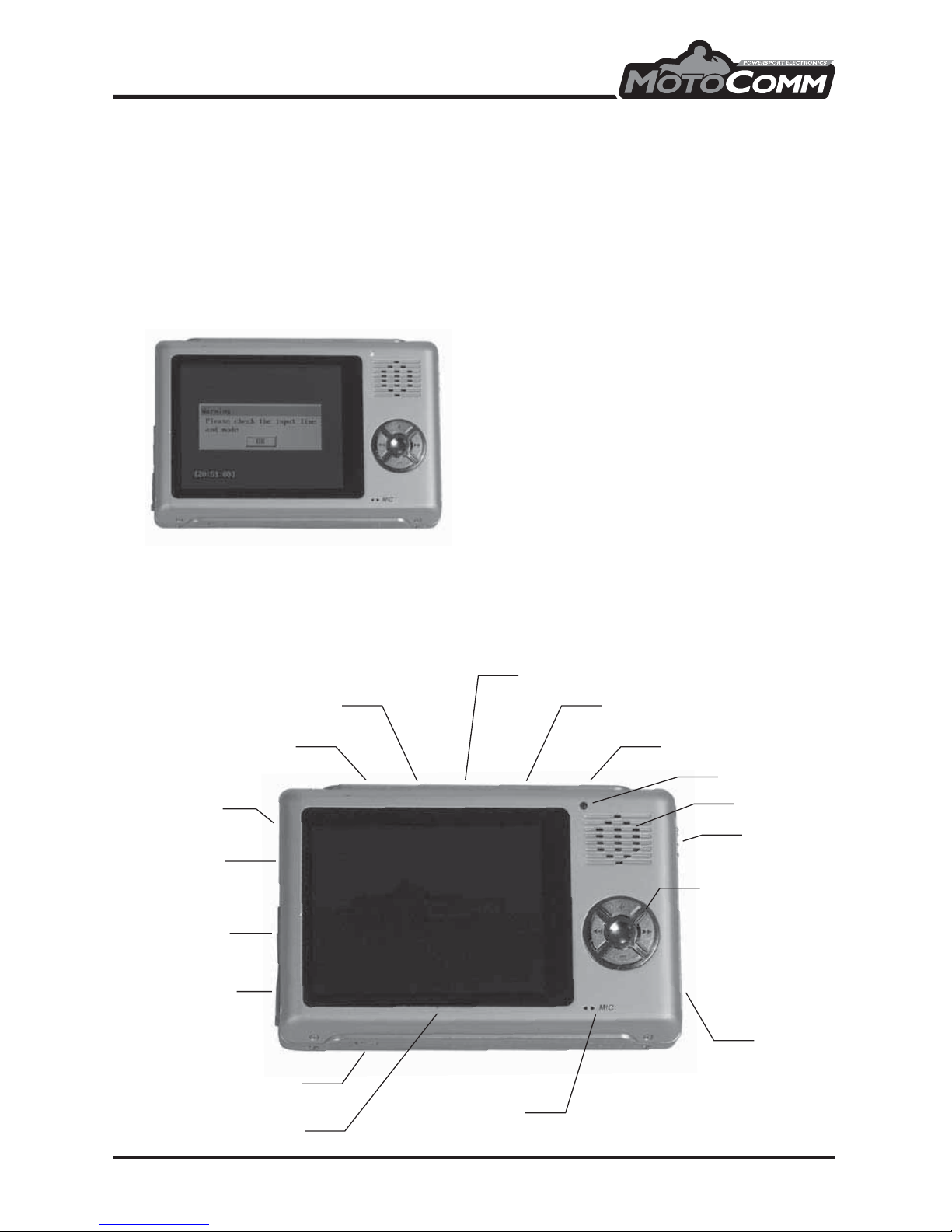
DSR-7680-3G Initial Instructions / Controls . . . . . . . . . . . . . . . . . . . . . . . . . . . . . . . . . . . . . . . . . . . . . . . . . . . . 7
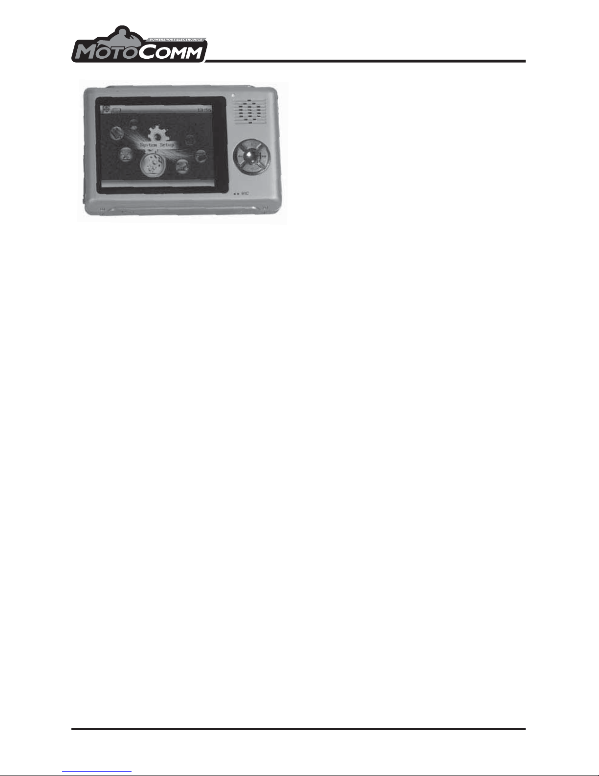
System Setup Menu. . . . . . . . . . . . . . . . . . . . . . . . . . . . . . . . . . . . . . . . . . . . . . . . . . . . . . . . . . . . . . . . . . . . . . . . . . 8
Recording a Video
Basic Setup / Connections . . . . . . . . . . . . . . . . . . . . . . . . . . . . . . . . . . . . . . . . . . . . . . . . . . . . . . . . . . . . . . 9
DSR-CM81 Camera Focusing . . . . . . . . . . . . . . . . . . . . . . . . . . . . . . . . . . . . . . . . . . . . . . . . . . . . . . . . . . 10
Camera Setup and Mounting . . . . . . . . . . . . . . . . . . . . . . . . . . . . . . . . . . . . . . . . . . . . . . . . . . . . . . . . . . 11
DSR-UM-1 Helmet Mounting . . . . . . . . . . . . . . . . . . . . . . . . . . . . . . . . . . . . . . . . . . . . . . . . . . . . . . 11 - 12
DSR-UM-1 Handlebar Mounting . . . . . . . . . . . . . . . . . . . . . . . . . . . . . . . . . . . . . . . . . . . . . . . . . . . . . . 13
DSR-BM-1 Pedestal Mount . . . . . . . . . . . . . . . . . . . . . . . . . . . . . . . . . . . . . . . . . . . . . . . . . . . . . . . . . . . . 14
DSR-SM4 Mounting Base . . . . . . . . . . . . . . . . . . . . . . . . . . . . . . . . . . . . . . . . . . . . . . . . . . . . . . . . . . . . . . 15
DSR-MIC-1 Remote Microphone Installation. . . . . . . . . . . . . . . . . . . . . . . . . . . . . . . . . . . . . . . . . . . . 15
DSR-BH-8AA Battery Holder Setup . . . . . . . . . . . . . . . . . . . . . . . . . . . . . . . . . . . . . . . . . . . . . . . . . . . . 16
DSR-12VDC-180CM Power Cable Installation . . . . . . . . . . . . . . . . . . . . . . . . . . . . . . . . . . . . . . . . . . 16
DVR Connection / Video Record Menu . . . . . . . . . . . . . . . . . . . . . . . . . . . . . . . . . . . . . . . . . . . . . . . . 17
My Videos Menu
Video Playback on LCD . . . . . . . . . . . . . . . . . . . . . . . . . . . . . . . . . . . . . . . . . . . . . . . . . . . . . . . . . . . . . . . . 18
Video Playback on TV. . . . . . . . . . . . . . . . . . . . . . . . . . . . . . . . . . . . . . . . . . . . . . . . . . . . . . . . . . . . . . 18 - 19
Deleting Videos . . . . . . . . . . . . . . . . . . . . . . . . . . . . . . . . . . . . . . . . . . . . . . . . . . . . . . . . . . . . . . . . . . . . . . 19
Video Playback on Computer
Transfering Video Files . . . . . . . . . . . . . . . . . . . . . . . . . . . . . . . . . . . . . . . . . . . . . . . . . . . . . . . . . . . . . . . . 20
Video Playback . . . . . . . . . . . . . . . . . . . . . . . . . . . . . . . . . . . . . . . . . . . . . . . . . . . . . . . . . . . . . . . . . . . . . . . . 21
Software Installation . . . . . . . . . . . . . . . . . . . . . . . . . . . . . . . . . . . . . . . . . . . . . . . . . . . . . . . . . . . . . . . . . . 21
SD Cards . . . . . . . . . . . . . . . . . . . . . . . . . . . . . . . . . . . . . . . . . . . . . . . . . . . . . . . . . . . . . . . . . . . . . . . . . . . . . . . . . . 21
Listening to MP3 Files . . . . . . . . . . . . . . . . . . . . . . . . . . . . . . . . . . . . . . . . . . . . . . . . . . . . . . . . . . . . . . . . . . 22 - 25
Tools . . . . . . . . . . . . . . . . . . . . . . . . . . . . . . . . . . . . . . . . . . . . . . . . . . . . . . . . . . . . . . . . . . . . . . . . . . . . . . . . . . . . . . 26
My Files. . . . . . . . . . . . . . . . . . . . . . . . . . . . . . . . . . . . . . . . . . . . . . . . . . . . . . . . . . . . . . . . . . . . . . . . . . . . . . . . . . . . 26
Games . . . . . . . . . . . . . . . . . . . . . . . . . . . . . . . . . . . . . . . . . . . . . . . . . . . . . . . . . . . . . . . . . . . . . . . . . . . . . . . . . . . . 27
Audio Record . . . . . . . . . . . . . . . . . . . . . . . . . . . . . . . . . . . . . . . . . . . . . . . . . . . . . . . . . . . . . . . . . . . . . . . . . . . . . . 27
My Photos . . . . . . . . . . . . . . . . . . . . . . . . . . . . . . . . . . . . . . . . . . . . . . . . . . . . . . . . . . . . . . . . . . . . . . . . . . . . . . . . 28
Company Information. . . . . . . . . . . . . . . . . . . . . . . . . . . . . . . . . . . . . . . . . . . . . . . . . . . . . . . . . . . . . . . . . . . . . . 28

DSR-1003G 4
The DSR-1003G includes many components. Please review the list below and make sure that
your system includes all items. If any component of the system is missing please contact
MotoComm at 1-877-624-6869 (toll-free) or by email at info@motocomm.com.
Qty. Part Number Description
1 DSR-CM81 Helmet/Bike Camera
1 DSR-7680-3G Digital Video Recorder/Playback Unit
1 DSR-MIC-1 Remote Microphone
1 DSR-BH-8AA Battery Holder
1 T-40 (MT-40) Stereo Helmet Speakers
1 TC-1 (MT-VX9) Music Adapter Cable for Helmet Speakers
1 DSR-BM-1 Pedestal Ball Camera Mount
1 DSR-UM-1 Universal Camera Mount
1 DSR-JUNC-1 4-Way Junction Cable
1 EXT-6 Coiled Extension Cable for Camera
1 EXT-6-180CM-S 6’ Straight Extension Cable for Camera
1 EXT-4 Coiled Extension Cable for Microphone
1 EXT-4-180CM-S 6’ Straight Extension Cable for Microphone
1 DSR-12VDC-180CM 6’ 12VDC Power Cord with Fuse
1 DSR-VAC-1 Video/Audio Cable
1 DSR-3.5S-1 3.5mm Stereo Patch Cable
1 DSR-USB-1 USB Cable
1 DSR-EPS-1 Earphone Speaker Headset
1 DSR-WS-1 Wrist Strap for DSR-7680-3G
1 DSR-AC-1 AC Adapter/Charger for DSR-7680-3G
1 DSR-VP-1 Carrying Case for DSR-7680-3G
1 ACC-1 Mounting Accessories for T-40 Speakers
3 DSR-SM4 Screw-Down Mounting Base for Camera
3 DSR-RT675 Medium Cable Tie for DSR-SM4
3 DSR-RT1100 Large Cable Tie for DSR-SM4
1 DSR-FOAM Adhesive-Backed Foam Cushion for DSR-UM-1
1 DSR-PB306 Plastic Carrying Case
All parts are available separately. Check with your dealer or contact MotoComm for details.

DSR-1003G
5
DSR-7680-3G Battery Charging
The DSR-7680-3G features an internal lithium-ion battery. With a full charge the battery will
operate the DSR-7680-3G for approximately 6 hours with the LCD screen on. For longer
operating durations, use the LCD Auto OFF battery conservation feature (see Setup Menu).
IMPORTANT: Fully charge the DSR-7680-3G internal battery prior to initial use.
To charge battery...
(1) Insert DSR-AC-1 into standard 110V AC wall outlet. Make sure that the LED light on the
DSR-AC-1 turns on when plugged into the wall outlet.
(2) Turn o DSR-7680-3G. NOTE: The
DSR-7680-3G may also be charged while
turned on, but the charging takes longer.
(3) Insert DSR-AC-1 plug into the DSR-7680-3G
charging port.
(4) The LED on the front of the DSR-7680-3G
will be solid red while the battery is charging.
(5) Charging is complete with the red LED turns o.
Connector Information
MotoComm’s mini DIN connectors feature a weatherproof molding. This weatherproof molding
is designed for a tight t. When mating these connectors for the rst time, it WILL BE DIFFICULT!
Take extra care in lining up the arrows on the connectors and slowly (but rmly!) push the
connectors together. It is a good idea to leave the plugs connected for several hours. This will
help‘mold’the connectors together and make for an ideal t. Subsequent connections will not be
as dicult.

DSR-1003G 6
(1) Cut 2 small pieces of the DSR-FOAM material and stick them to the
inside surface of the DSR-UM-1 as shown.
(2) Place the DSR-CM81 in the DSR-UM-1 and tighten down the machine
screw and nut so that the camera is secure but can still be rotated in
mount.
(3) Cover the at part of the DSR-UM-1 with one side of the provided
hook-and-loop material, as shown.
(4) Stick the mating side of the provided hook-and-loop material to the
inside surface of the helmet shell. Attach the camera as shown.
(5) Connect the DSR-MIC-1 remote microphone to the DSR-JUNC-1
4-way junction cable (4pin connection).
(6) Leaving the DSR-CM81 camera on your helmet, connect it to the
DSR-JUNC-1 (6pin connection). If needed, use the EXT-6 coiled
extension cable for additional reach.
(7) Plug the DSR-JUNC-1 into the AV IN (top) jack on the DSR-7680-3G
DVR.
(8) Install 8 AA batteries into the DSR-BH-8AA battery holder and
connect it to the DSR-JUNC-1. NOTE: The 8 AA batteries power the
DSR-CM81 camera and DSR-MIC-1 remote microphone. Whenever
the battery pack is connected, the camera and microphone are ON
and are drawing power. The DSR-7680-3G DVR has its own separate
internal battery. The two power sources do not interact in any way.
(9) Turn on the DSR-7680-3G by pressing the power button for 5 seconds
and then releasing.
(10) The DSR-7680-3G defaults to the video record screen. If everything is
connected correctly and the batteries are good, you will see the
image from the camera on the DSR0-7680-3G display.
(11) Rotate the DSR-CM81 camera to set the horizon and then tighten
down the screw and nut on the DSR-UM-1 to secure the camera.
(12) If required adjust the vertical angle of the camera by reattaching the
hook-and-loop pieces at the correct angle. Keep in mind your normal
riding position - a hour long video of your tank is not that exciting!
(13) Press the enter (fII)button to start recording. Slide the Hold (control
lock) switch to the up, or locked, position. Put the microphone, DVR
unit, and battery pack in your jacket pocket, tank bag, waist pack,
camelback, etc. and go ride!
Quick Setup Guide
Although we highly reccomend that you read the entire manual, we also realize that you want to
get out and use your DSR-1003G immediately! Follow the steps below to start recording as
quickly as possible.

DSR-1003G
7
DSR-7680-3G Initial Instructions and Controls
Initial Instructions
(1) To turn on and o the DSR-7680-3G, press and hold the on/o button for 5 seconds and then
release it.
(2) When turned on, the DSR-7680-3G defaults to the Video Record screen - not the Main Menu
screen. The DSR-1003G is designed this way to make recording videos a quick and simple
one-button procedure - turn on the DSR-7680-3G with camera and cabling connected, and
push the enter (fII)button to start recording.
IMPORTANT: If you do NOT have the camera and
battery pack connected to the DSR-7680-3G
upon turn on, you will receive a warning
message asking you to check the AV input line
(camera connection) - see photo. See the Quick
Setup Guide or Recording a Video sections for
details on connecting the camera and cabling.
(3) To access the Main Menu from the Video Record screen (default screen after turn on) push
the escape (ESC) button.
Controls and Features
Power On/O
Mode
Play/Pause
M
Escape
AV Line In
(camera input)
AV Line Out
(headphones
out)
USB
Power/Charge
Reset
Navigation Buttons
+ : Up
- : Down
ee : Left
ff : Right
Internal Microphone
(for Audio Record feature ONLY)
LCD Screen
SD Card
LED Light
Speaker
Hold
Switch

DSR-1003G 8
System Setup Menu
To access the System Setup menu, use the left
(ee ) and right (ff) navigation buttons on the
front panel to select the System Setup icon and
the press the enter (fII)button. To navigate in
the System Setup menu:
(1) Use the navigation buttons (ee , ff, +, - ) to
highlight the selection.
(2) Use the enter (fII)button to select.
(3) Use the escape (ESC) button to exit.
Default
The Default feature reverts the DSR-7680-3G back to its factory default system settings.
Sound
The Sound feature allows you to turn the internal speaker and the key tone on and o.
(1) To turn the speaker and/or key tone on or o, highlight the desired selection and press the
enter (fII)button.
(2) “Success”will display on the LCD and return you to the System Setup menu.
Pwr AutoO
The Pwr AutoO feature will automatically turn o the DSR-7680-3G after a specied duration of
inactivity. IMPORTANT - It is recommended to have the Pwr AutoO feature set to Never.
(1) To activate the automatic power o feature, highlight the desired time setting (3 minutes, 15
minutes or 60 minutes) and press the enter (fII)button.
(2) “Success” will display on the LCD and return you to the System Setup menu.
Time
Sets the date and time for the DSR-7680-3G.
(1) Use the left (ee ) and right (ff) navigation buttons to select the year, month, day, hour and
minute.
(2) Use the plus ( + ) and minus ( - ) navigation buttons to change the date and time and press
the enter (fII)button.
(2) “Success” will display on the LCD and return you to the System Setup menu.
LCD AutoO
The LCD AutoO feature automatically turns o the LCD screen’s backlighting after a specied
duration of time. This feature helps conserve battery life - the LCD backlighting is one of the major
power drains of the system.
(1) To activate the LCD auto o feature, highlight the desired time setting (half min, one min,
three min) and press the enter (fII)button.
(2) “Success”will display on the LCD and return you to the System Setup menu.
(3) The LCD backlighting will now turn o automatically. Pressing any button on the
DSR-7680-3G will turn the backlighting on again.
(4) HINT: To avoid accidentally pushing a button and turning the backlighting on, use the Hold
switch on the side of the DSR-7680-3G. The hold switch locks the control buttons and makes
them inactive.

DSR-1003G
9
TIP: Use the above basic wiring information as the starting point for any installation. The camera and remote
microphone mounting locations will determine which, if any, of the extension cables will be used in your
install. When mapping out your install, keep in mind that you will want to protect the DSR-7680-3G unit from
the elements, while still being able to easily access it.
Recording a Video
Your DSR-1003G comes with everything you need (and more!) to record videos. There are many
possible mounting congurations with the DSR-1003G, but they all start with the same basic
setup. Use the information below as a starting point for your custom conguration and
installation.
Basic Setup
There are over 20 items included with the DSR-1003G, but only 5 are required to record a video:
(1) DSR-7680-3G DVR unit
(2) DSR-JUNC-1 4-Way Junction Cable
(3) DSR-CM81 Camera
(4) DSR-MIC-1 Remote Microphone
(5) DSR-BH-8AA Battery Pack, or DSR-12VDC-180CM
Connections
(1) The DSR-JUNC-1 cable connects the 4 basic setup components of the DSR-1003G.
(2) The DSR-CM81 camera connects to the 6pin mini-DIN connector on the DSR-JUNC-1.
Depending on your installation, the camera connection can be extended using either the
EXT-6 coiled extension cable or the EXT-6-180CM six foot straight extension cable.
(3) The DSR-MIC-1 remote microphone connects to the 4pin mini-DIN connector on the
DSR-JUNC-1. Depending on your installation, the microphone connection can be extended
using either the EXT-4 coiled extension cable or the EXT-4-180CM six foot straight extension
cable.
(4) The DSR-JUNC-1’s 3.5mm, 4-contact plug connects to the DSR-7680-3G DVR AV Line IN jack.
(5) The DSR-BH-8AA or DSR-12VDC-180CM connects to the barrel-type DC power connector on
the DSR-JUNC-1.
Installation and Operation Note: The DSR-BH-8AA (12 volt battery pack) and the DSR-12VDC-180CM (12 volt
power cable) power the DSR-CM81 camera and DSR-MIC-1 remote microphone. **IMPORTANT** Whenever
the battery pack or power cable are connected, the camera and microphone are ON and are drawing power.
The DSR-7680-3G has its own separate internal battery. The two power sources do not interact in any way.
Basic Setup Connections
- OR -

DSR-1003G 10
DSR-CM81 Camera Focusing
The DSR-CM81 is focused at the factory, and the camera should be correctly focused out of the
box. However, if you want to change the focus of the camera, or nd in the future that it needs
to be adjusted, follow these steps...
(1) With the DSR-1003G in the basic setup
(see page 10), turn on the
DSR-7680-3G so that the camera
image can be viewed on the LCD
screen.
(2) Unscrew the lens cover from the
DSR-CM81 camera body. Note that
there is a rubber o-ring that creates a
weatherproof seal between the lens
cover and the camera body.
(3) Loosen the small set screw so that the
camera lens can be rotated and
focused.
(4) Determine the distance at which you
want the camera to be focused at, and
point the camera at an object at that
distance.
(5) Carefully turn the camera lens
clockwise or counterclockwise, while
looking at the DSR-7680-3G screen, to
focus the camera on the object.
(6) When in focus, carefully tighten down
the set screw to secure the lens in the
focused position.
(7) Screw the lens cover back onto the
camera body. Make sure the lens cover
is tight so that the rubber o-ring
creates a proper seal.
Camera Body
Lens Cover
Rubber O-Ring
Set Screw
Camera Lens

DSR-1003G
11
Camera Setup and Mounting
Your DSR-1003G comes with three dierent camera mounts: the DSR-UM-1 Universal Helmet and
Bike Mount, the DSR-BM-1 Pedestal Ball Mount, and the DSR-SM4 Screw-Down Mounting Base.
DSR-UM-1 Universal Mount
The DSR-UM-1 Universal Mount can be used for both helmet mounting and handlebar mounting
the camera.
DSR-UM-1 Helmet Mounting
(1) Cut 2 small pieces of the
DSR-FOAM material and stick
them to the inside surface of
the DSR-UM-1 as shown.
(2) Place the DSR-CM81 in the
DSR-UM-1 and tighten down
the machine screw and nut
so that the camera is secure
but can still be rotated in
mount.
The DSR-UM-1 is not designed to be a permanent mounting solution. Do not leave the DSR-UM-1
attached to any surface for a prolonged period. Make sure all mounts, wires and connections are
secure before riding. Check for loose mounts and connections during and after each ride.
DSR-FOAM
DSR-FOAM
Machine Screw / Nut

DSR-1003G 12
(3) Cover the at part of the
DSR-UM-1 with one side of
the provided hook-and-loop
material, as shown.
(4) Stick the mating side of the
provided hook-and-loop
material to the inside surface
of the helmet shell. Attach
the camera as shown.
(5) Use the active LCD screen
and rotate the DSR-CM81
camera to set the horizon
and then tighten down the
screw and nut on the
DSR-UM-1 to secure the
camera.
(6) If required adjust the vertical
angle of the camera by
reattaching the
hook-and-loop pieces at the
correct angle. Keep in mind
your normal riding position.
Hook-and-Loop Material

DSR-1003G
13
DSR-UM-1 Handlebar Mounting
(1) Cut 1 piece of the DSR-FOAM
and stick it to the at side of
the DSR-UM-1, as shown.
(2) Place the DSR-CM81 on the
foam piece and use 2
DSR-RT675 Medium or
DSR-RT1100 Large Size Cable
Ties to secure the camera to
the mount, as shown.
(3) Handlebar mount example
of the DSR-UM-1 with the
camera strapped to the at
side. Tip: Use more
DSR-FOAM on the
bar-mount end so as to not
scratch your bike!
DSR-FOAM
DSR-RT675
or DSR-RT1100

DSR-1003G 14
DSR-BM-1 Pedestal Ball Mount
(1) Screw the DSR-BM-1 into the
back side of the camera until
nger tight. Loosen the
DSR-BM-1 set screw, position
the camera, and tighten the
set screw.
Tip: If vibration loosens the
camera from the DSR-BM-1,
use a thread-adhesive
(Loctite, etc.).
(2) Example of the DSR-BM-1
mounting on tail of bike.
The DSR-BM-1 features 3 mounting holes in the base of the mount. If the included mounting
screws are not ideal for your bike’s installation, then remove an existing fairing screw, etc. and
reattached with the DSR-BM-1 screwed down. Use the DSR-FOAM between the mount and bike.

DSR-1003G
15
DSR-SM4 Screw-Down Mounting Base
(1) Remove a body panel, or
other, screw and reattach
with the DSR-SM4 in place.
Insert a DSR-RT675 or
DSR-RT1100 cable tie
through the mounting base
and tighten it down with the
camera positioned.
TIP: Screws and adhesives may be
used to attach the DSR-SM4 to
almost any object or surface. Make
sure that any mounting method will
support the camera at speed.
DSR-MIC-1 Remote Microphone Installation
The DSR-MIC-1 has a variable gain
control located on the bottom of the
microphone case. The gain control is a
small, circuit board mounted
potentiometer.
To adjust the gain of the microphone,
remove the protective rubber cover
and use a small slotted screw driver to
SLOWLY adjust the potentiometer. To
increase the microphone gain, rotate
the control clockwise. To decrease the
gain, rotate the control
counter-clockwise. Only small
adjustments are required.
To mount the DSR-MIC-1 Remote Microphone use some of the provided adhesive-backed
hook-and-loop mounting tape to secure the microphone to the bike. The photo above shows an
example of the microphone mounted under the seat.

DSR-1003G 16
DSR-BH-8AA Battery Holder Setup
The DSR-BH-8AA holds 8 AA batteries and is one option to supply the camera and remote
microphone with the required 12 volts DC. With new, fresh alkaline batteries, the DSR-BH-8AA will
run the microphone and camera for approx. 12 hours continuous use. NOTE: Whenever the
battery pack is connected, the camera and microphone are ON and are drawing power. The
DSR-7680-3G DVR has its own separate internal battery. The two power sources do not interact in
any way.
(1) Insert 8 AA batteries into the DSR-BH-8AA
as indicated on the battery compartments.
(2) Use one or more of the large cable ties
(DSR-RT1100) to secure the batteries in the
holder.
(3) Keep batteries secure and dry while using.
DSR-12VDC-180CM Power Cable Installation
The DSR-12VDC-180CM is another option for powering the camera and remote microphone. The
camera and microphone operate o of 12 volts DC and may be powered by a standard vehicle
electrical system. The camera and microphone combined current draw is approx. 120mA - make
sure that the electrical system is capable of handling this current draw.
(1) Connect the red wire (fused line) to the
positive (+) 12 volt DC power source. It is
recommended to make the connection at
the fuse box or other switched power
source.
(2) Connect the black wire (ground) to the
negative (-) side of the 12 volt DC power
source.
NOTE: Motorcycle and powersport vehicle electrical systems can be ‘noisy’ and can generate
interference with installed electronic equipment. If you experience interference when using the DC
power cable, try using the battery holder to power the camera and remote microphone.

DSR-1003G
17
DVR Connection
To connect your camera and microphone installation to the DSR-7680-3G DVR unit, insert the
3.5mm, 4-contact plug from the DSR-JUNC-1 into the AV Line In jack on the DVR unit.
Video Record Menu
The Video Record screen is the default
screen after turn on. This feature
makes recording a video a one-button
process after turn on.
To access the Video Record screen
from the Main Menu, use the left (ee )
and right (ff) navigation buttons on
the front panel to select the Video
Record icon and the press the enter (f
II)button. See photo.
To record a video:
(1) Make sure the image from the camera is displayed on the LCD screen.
(2) Press the enter (fII) button to start recording. A red record symbol (REC) will appear on the
LCD indicating that the system is recording.
(3) To stop recording, press the enter (fII)button again. Note: Each time a video recording is
stopped and started again, a new video le is created.
Video File Information:
(1) The DSR-1003G saves the recorded videos in the 3GP le format. 3GP is a widely used le
format that is compatible with most PC’s and MAC’s. To learn more about 3GP go to
www.3GP.com. If your computer’s media player will not playback a 3GP le, see the Software
section of this manual (page 21).
(2) The DSR-1003G records the video in 320x240 resolution at 30 frames per second.
Troubleshooting:
If there is no camera image on the LCD screen, or the screen displays the warning message“Please
check the input line and mode”, check that the following:
(1) Conrm that the 3.5mm, 4-contact plug from the DSR-JUNC-1 is completely seated into the
DSR-7680-3G AV IN jack (the top jack on the side of the unit).
(2) Conrm that the DSR-CM81 camera is connected to the DSR-JUNC-1 and that none of the
pins on the 6pin mini-DIN connector(s) are bent or broken.
(3) Conrm that the DSR-MIC-1 remote microphone is connected to the DSR-JUNC-1 and that
none of the pins on the 4pin mini-DIN connector(s) are bent or broken.
(4) Conrm that the DSR-BH-8AA battery pack, or the DSR-12VDC-180CM power cable, is
connected to the DSR-JUNC-1 and supplying voltage to the camera and microphone.

DSR-1003G 18
My Videos Menu
The My Videos menu is where you can access
and manage your recorded videos. To access the
My Videos screen from the Main Menu, use the
left (ee ) and right (ff) navigation buttons on
the front panel to select the My Videos icon and
the press the enter (fII)button.
In the My Videos menu you can view, play, and
delete videos.
Viewing Video List
(1) The list of videos may be viewed in list form (default) or thumbnail image of the rst frame of
the video.
(2) To change video list view, press the menu ( M ) button to bring up the My Videos options
menu.
(3) Use the up ( + ) and down ( - ) navigation buttons to highlight the Disp Mode option.
(4) Press the right navigation (ff ) button to open the Disp Mode options menu, and use the up
( + ) and down ( - ) navigation buttons to highlight either the List or Thumbnail views.
(5) Press the enter (fII) button to select.
Playing Videos
From the My Videos menu, you can playback videos on the DSR-7680-3G screen or directly to a
television with composite (RCA) inputs with the provided DSR-VAC-1 cable.
Video Playback on LCD
(1) Use the navigation buttons (ee ,ff, +,-)to select the video your want to play.
(2) Press the enter (fII) button to play.
(3) The video playback screen will appear and your video will play.
(a) To pause the video playback, press the enter (fII)button again.
(b) To adjust the volume, press the up ( + ) and down ( - ) navigation buttons.
(c) To skip forward to the next video, press the right navigation (ff ) button.
(d) To skip backward to the previous video, press the left navigation (ee ) button.
(e) To fast forward a video, press the mode (MODE) button (the volume indicator will
turn blue color) then press the right navigation (ff ) button.
(e) To reverse a video, press the mode (MODE) button (the volume indicator will turn
blue color) then press the left navigation (ee ) button.
(f) To stop playback and return to the video list, press the escape (ESC) button.
Video Playback on Television
(1) Connect the DSR-VAC-1 cable to the AV OUT jack on the DSR-7680-3G and to available RCA
inputs on your television. Make sure to activate the input on your television.
(2) From the My Videos list screen, press the menu ( M ) button and highlight the TV Output
option. Press the right navigation (ff ) button to open the TV Output options menu, and use
the up ( + ) and down ( - ) navigation buttons to highlight the LCD, NTSC, or PAL output
options. Press the enter (fII)button to select.
(a) Select LCD (default) to playback videos on the DSR-7680-3G screen.

DSR-1003G
19
(b) Select NTSC option to playback videos on NTSC televisions (the standard for the
USA, Canada, and other countries).
(c) Select PAL option to playback videos on PAL televisions (the standard for Europe
and other countries).
(3) Use the navigation buttons (ee ,ff, +,-)to select the video your want to play.
(4) Press the enter (fII) button to play.
(5) The LCD screen will turn o and the video will play on the television. IMPORTANT: Depending
on the size of your television, the video quality may be degraded slightly. The native
resolution of the video les are 320x240 and the DSR-7680-3G up scales the video for
playback to televisions.
(6) Control the playback of the video just as you would viewing it on the LCD screen.
Loop Mode
The Loop Mode option determines how the videos play back.
(1) From the My Videos list screen, press the menu ( M ) button and highlight the Loop Mode
option.
(2) Press the right navigation (ff ) button to open the Loop Mode options menu, and use the up
( + ) and down ( - ) navigation buttons to highlight either Current, All, or Random.
(a) Current will continuously playback one video.
(b) All will continuously playback all videos in the video list.
(c) Random will playback all the videos in a random order.
(3) Press the enter (fII) button to select.
Deleting Videos and File Protect
(1) From the My Videos list screen, press the menu ( M ) button and highlight the Del File option.
(2) Press the right navigation (ff ) button to open the Del File options menu, and use the up
( + ) and down ( - ) navigation buttons to highlight either Current or All.
(a) Selecting Current will delete only the video le that is currently selected in the list.
(b) Selecting All will delete ALL THE VIDEO FILES!!!!
(3) Press the enter (fII) button to select.
(4) A warning window will appear conrming that you actually want to delete the le. Use the
navigation buttons to highlight OK or Cancel, and press the enter (fII)button to conrm.
(5) Video les can be locked and protected against accidental deleting. To lock a le, press the
menu ( M ) button and highlight the File Protect option.
(6) Press the right navigation (ff ) button to open the File Protect options menu, and use the up
( + ) and down ( - ) navigation buttons to highlight either Lock or Unlock.
(a) Select Lock to lock and protect a le.
(b) Select Unlock to unlock a previously locked le.
(7) Press the enter (fII) button to select. A padlock symbol will appear next to locked les.

DSR-1003G 20
Video Playback on Computer
The DSR-1003G features a USB port and cable for transferring videos to your computer. With the
appropriate software, you can watch and edit the videos on your computer.
Transferring Videos
(1) Turn on the DSR-7680-3G and go to the
Main Menu screen.
(2) Connect the DSR-USB-1 cable to the USB
port on your computer, and the other end
of the DSR-USB-1 cable to the USB port on
the side of the DSR-7680-3G
(3) The screen on the DSR-7680-3G will change
to a picture of a USB plug, conrming that
the DSR-7680-3G is properly connected to
your computer.
(4) Depending on your computer and
operating system, a window on your
computer may automatically appear
indicating the connection of a “Removable
Disk”or “External Drive”. If it does, select the
open folder option. If your computer does
not automatically recognize the connection
of the DSR-7680-3G, go to the My
Computer or other window that lists all
connected devices and drives and select
the Removable Disk icon that appeared
after connecting.
(5) If you have a SD card installed in the
DSR-7680-3G, then you will see 2 new
Removable Disk icons. The SD card will be
the rst drive letter alphabetically and the
internal memory of the DSR-7680-3G will
be the second drive letter alphabetically.
(6) Open the My Videos folder and copy or
‘drag and drop’ the desired videos to your
computer.
(7) After transfer, disconnect the DSR-7680-3G
from your computer using the proper
method (Safely Remove Hardware
command, etc.), and then unplug the
DSR-USB-1.
Table of contents
Other MotoComm Action Camera manuals