Motomaster 058-7949-6 User manual

INSTRUCTION MANUAL
AIR COMPRESSOR
5-GALLON (18.9 L)
058-7949-6
If any parts are
missing or damaged,
or if you
have any
questions, please call our toll-free
helpline
at 1-888-942-6686.
Read and understand this instruction manual thoroughly before using the product. It contains
important information for your safety as well as operating and maintenance advice.
Keep this instruction manual for future use. Should this product be passed on to a third party, this
instruction manual must be included.
An English version of this manual is available online at: www.canadiantire.ca/manuals
中文版說明書請參照: www.canadiantire.ca/manuals Quick Start Guide
Version: 01 QUICK START GUIDE
TM
MC
058-7949-6-Air-Compressor-5G-EN-05.indd 1-2 5/14/12 11:14 AM
VY03A1872982

2
STEP 1
Set the pressure switch to the OFF
position.
OFF
STEP 2
Quick Start Guide
Technical Specifications 3
Safety Guidelines 4 – 6
Key Parts Diagram 7
Key Parts List 8 – 9
Intended Use 10
Assembly 11 – 12
Operating Instructions 13 – 17
Maintenance 18 – 19
Troubleshooting 20 – 21
Exploded View 22
Parts List 23
Warranty 24 – 25
QUICK START GUIDE QUICK START GUIDE TABLE OF CONTENTS
STEP 3
Attach hose and accessories (not
provided).
Apply plumber's tape on all the
threads to prevent air leakage.
1
2
3
45
6
7
81
2
3
45
6
7
8
STEP 4
Check and verify the pump oil level.
Perform this routinely to prevent the
motor from seizing.
STEP 5
Close the tank drain valve, located on
the bottom of the air tank.
CLOSE
TM
MC
STEP 6
Plug in the power cord.
Caution: Connect the power cord
only after break-in process has
been competed, otherwise motor
might get damaged (see Breaking-
in the pump, page 13).
STEP 7
Set the pressure switch to the ON
position.
ON
STEP 8
Turn the air pressure regulator knob
clockwise until desired pressure is
reached.
WARNING! Fill with compressor oil before using.
Running with NO OIL or LOW OIL may damage the motor.
058-7949-6-Air-Compressor-5G-EN-05.indd 3-2 5/14/12 11:14 AM
Turn the air pressure regulator knob
counter-clockwise until pressure
drops down to zero on output gauge.

3 4
TECHNICAL SPECIFICATIONS SAFETY GUIDELINES
Product Number 058-7949-6
Horsepower 2
Tank Size 2 1/2 x2 U.S. gallons (18.9 L)
Air Delivery (SCFM*) @ 40 PSI 5.1
Air Delivery (SCFM*) @ 90 PSI 4.1
Cut-In Pressure (PSI) 95
Cut-Out Pressure (PSI) 125
Pump Design Cast-iron cylinder, oil-lubricated,
Motor 3,400 RPM
Power 120 V, 60 Hz, 13 A
Weight 55 lb (25 kg)
Power Cord SJT 14 AWG / 78’’ (1.98 m)
Extension Cord SJT 12 AWG / Maximum 30’ (9.1 m)
* SCFM: Standard Cubic Feet per Minute (= The volumetric flow rate of a gas corrected to
standardized conditions of temperature and pressure.)
This manual contains information that relates to PROTECTING
PERSONAL SAFETY and PREVENTING EQUIPMENT PROBLEMS. It is very
important to read this manual carefully and understand it thoroughly
before using the product. The symbols listed below are used to indicate
this information.
DANGER! Potential hazard that will result in serious injury or loss of life.
WARNING! Potential hazard that could result in serious injury or loss of life.
CAUTION!
Potential hazard that may result in moderate injury or damage to equipment.
IMPORTANT! Installation, operation or maintenance information that is important but not hazard
related.
Safety Advice
DANGER!
1. RISK OF FIRE OR EXPLOSION. Do not spray a flammable or combustible liquid or paint near
sparks, flames, pilot lights or in a confined area. The spray area must be well-ventilated. Keep
compressor at least 20’ (6 m) away from spray area. Do not carry and operate the compressor or
any other electrical device near the spray area. Never smoke when spraying. Use a minimum of
25’ (7.6 m) of hose to connect a spray gun to the compressor.
2. RISK OF ELECTRIC SHOCK. Do not expose to rain. Store indoors. Hazardous voltage. Disconnect
from power source before servicing. Compressor must be grounded. Do not use grounding
adaptors.
3. RISK OF BURSTING. Make sure the regulator is adjusted so that the compressor outlet pressure is
set lower than the maximum operating pressure of the spray gun or tool. Before starting the
compressor, pull the ring on the safety valve to make sure the valve moves freely (see diagram on
page 17). Drain water from tank after each use. Do not weld or repair tank.
058-7949-6-Air-Compressor-5G-EN-05.indd 3-4 5/14/12 11:14 AM

5 6
4. RISK OF PERSONAL INJURY. Never spray compressed air or material at self or others.
5. RISK OF BURSTING. Check the maximum pressure rating in the manual or identification label. The
compressor outlet pressure must be regulated so that it does not exceed the maximum pressure
rating. Relieve all pressure in the hose before removing or attaching accessories.
6. RISK OF BURSTING. Do not adjust the pressure switch or safety valve for any reason. They have
been preset at the factory for this compressor’s maximum pressure. Tampering with the pressure
switch or the safety valve may cause personal injury or property damage.
7. RISK OF BURNS. The pump and the manifold generate high temperatures. In order to avoid burns
or other injuries, do not touch the pump, the manifold or the transfer tube while the compressor is
running. Allow the parts to cool down before handling or servicing. Keep children away from the
compressor at all times.
8.
RISK TO BREATHING. Be certain to read all labels when you are spraying paints or toxic materials,
and follow all safety instructions. Use a respirator mask if there is a chance of inhaling anything you
are spraying. Also, NEVER directly inhale the air produced by a compressor.
9. RISK OF EYE INJURY. Wear ANSI Z87.1 approved safety goggles when using an air compressor. Do
not point any nozzle or sprayer toward a person or any part of the body. Serious injury may occur if
the spray penetrates the skin.
WARNING!
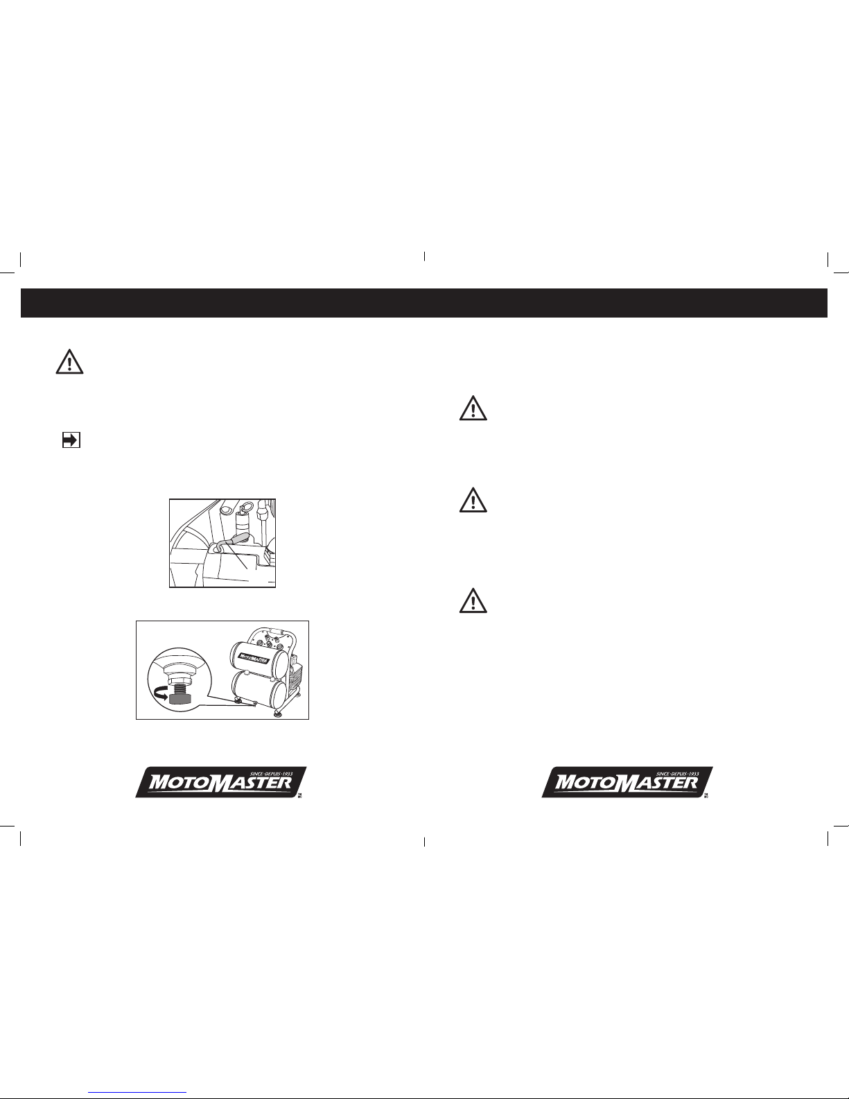
1. Pull the pressure safety valve ring every day in order to ensure that the valve is
functioning properly.
2. The compressor must be located in a well-ventilated area for cooling, and
must be a minimum of 12” (31 cm) away from the nearest wall.
3. Protect the air hose and the power cord from damage and puncture. Inspect them for weak or worn spots every
week, and replace them if necessary.
4. Always wear hearing protection when using an air compressor. Failure to do so may result in hearing loss.
5. Do not carry the compressor while it is running.
6. Do not operate the compressor if it is not in a stable position.
7. Do not operate the compressor on a rooftop or an elevated position that could allow the unit to fall or be tipped
over.
8. Always replace a damaged gauge before operating the unit again.
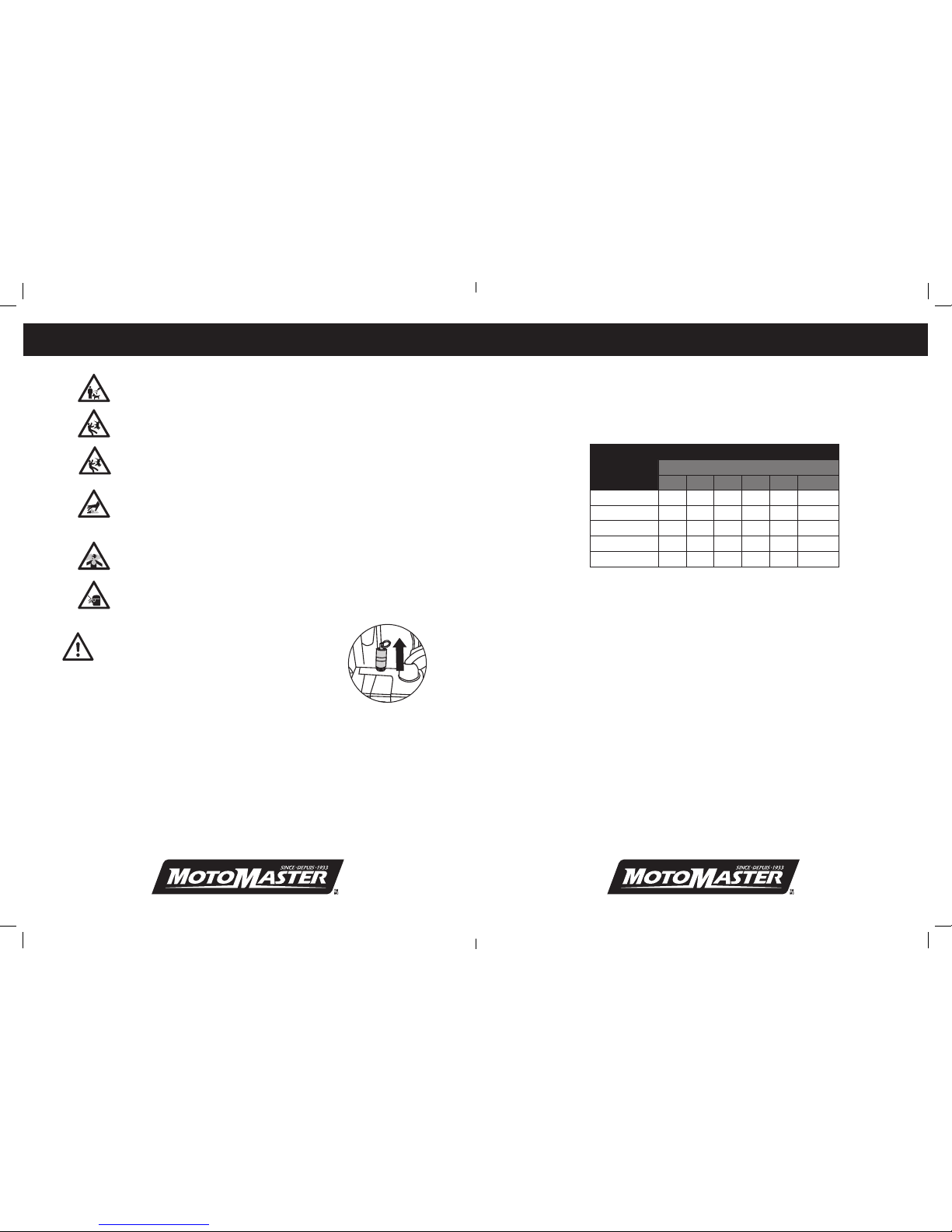
Extension cords
As the distance from the supply outlet increases, you must use a heavier gauge extension cord. Using extension
cords with inadequately sized wire causes a serious drip in voltage, resulting in loss of power and possible product
damage. Refer to the table here to determine the required minimum wire size.
Recommended Minimum Wire Gauge for Extension Cords* (120 V)
AMPERE
RATING
CORD SIZE IN AWG (AMERICAN WIRE GAUGE)
Extension cord length in feet
25' 50' 75' 100' 150' 200'
0 - 5 16 16 16 14 12 12
5.1- 8 16 16 14 12 10 --
8.1 - 12 14 14 12 10 -- --
12.1 - 15 12 12 10 10 -- --
15.1 - 20 10 10 10 -- -- --
* Based on limiting the line voltage drop to five volts at 150% of the rated amperes.
The smaller the gauge number of the wire, the greater the capacity of the cord. For example, a 14-gauge cord can
carry a higher current than a 16-gauge cord. When using more than one extension cord to make up the total length,
be sure each cord contains at least the minimum wire size required.
Guidelines for using extension cords
• Ifyouareusinganextensioncordoutdoors,besureitismarkedwiththesufx"W-A"("W"inCanada)to
indicate it is acceptable for outdoor use.
• Ensureyourextensioncordisproperlywiredandingoodelectricalcondition.Alwaysreplaceadamaged
extension cord or have it repaired by a qualified technician before using it.
• Protectyourextensioncordsfromsharpobjects,excessheatanddamporwetareas.
SAFETY GUIDELINES (cont.)SAFETY GUIDELINES (cont.)
058-7949-6-Air-Compressor-5G-EN-05.indd 5-6 5/14/12 11:14 AM

7 8
TM
MC
B. AIR COMPRESSOR PUMP: The pump compresses the air and discharges it into the tank via the piston that
moves up and down in the cylinder.
C. PRESSURE SWITCH: This switch turns the compressor on and off. It is operated manually and when it is in the
ON position, it allows the motor to start if the pressure in the air tank is below the factory set cut-in pressure,
and allows the motor to stop if the pressure in the air tank reaches the factory set cut-out pressure. Be sure
to set this switch to the OFF position when the compressor is not being used and before unplugging the
compressor.
D. SAFETY VALVE: This valve is used to prevent system failure by draining pressure from the system when it
reaches a preset level if the pressure switch has not shut down the motor. It will pop open automatically, or it
can be activated manually by pulling the ring on the valve.
E. AIR PRESSURE REGULATOR: The regulator is used to adjust the pressure inside the line to the tool that is
being used. Turn the knob clockwise to increase the pressure and counter-clockwise to decrease the pressure.
[ WARNING! Do not exceed the tool’s maximum working pressure.
F. TANK PRESSURE GAUGE: The gauge measures the pressure level of the air that is stored in the tank. It cannot
be adjusted by the operator and it does not indicate the pressure inside the line.
G. OUTLET PRESSURE GAUGE: The gauge measures the regulated outlet pressure.
H. AIR OUTLET: The outlet is connected to the 1/4” (6.4 mm) NPT air hose.
I. AIR TANK DRAIN VALVE: The drain valve is used to remove moisture from the air tank after the compressor is
shut off.
[ WARNING! Do not attempt to open the drain valve when there is more than
10 PSI of air pressure in the tank.
J. AIR TANK: The tank is where the compressed air is stored.
AIR TANK
DRAIN VALVE (I)
PRESSURE
SWITCH (C)
AIR PRESSURE
REGULATOR (E)
SAFETY
VALVE (D)
OUTLET PRESSURE
GAUGE (G)
TANK PRESSURE
GAUGE (F)
AIR OUTLET (H)
POWER CORD (K)
AIR TANK (J)
KEY PARTS LISTKEY PARTS DIAGRAM
ELECTRIC
MOTOR (A)
AIR COMPRESSOR
PUMP (B)
OIL PLUG (M)
OIL SIGHT (L)
058-7949-6-Air-Compressor-5G-EN-05.indd 7-8 5/14/12 11:14 AM
A. ELECTRIC MOTOR: The motor is used to power the pump. It is equipped with at thermal overload protector.
If the motor overheats for any reason, the thermal overload protector will shut it down in order to prevent the
motor from being damaged.
Other manuals for 058-7949-6
1
Table of contents
Other Motomaster Air Compressor manuals