Motorline professional MC18 Instruction Manual

v3.0
REV. 01/2023
EN
USER/INSTALLER MANUAL
MC18

1A 1B
ENEN
INDEX
. CONTENT . SAFETY INSTRUCTIONS
1B
4A
CONNECTION OF COMPONENTS TO THE CONTROL BOARD
4B
TECHNICAL CHARACTERISTICS
6B
ESSENTIAL STEPS FOR INSTALLATION
11
INSTRUCTIONS FOR END CONSUMERS
8B
CODE | PUSH BUTTON CONFIGURATION
9B
CODE | FUNCTION NOT USED
10B
SLOW-SPEED PROGRAMMING
11
INSTRUCTIONS FOR SPECIALIZED TECHNICIANS
9A
T. MOT | SLOW-SPEED
10A
T.MOT | AUTOMATIC PROGRAMMING
9A
T. PAUSA | OPERATING LOGIC OF PHOTOCELLS
10A
T. PAUSA | AUTOMATION / MOTORS
6B
T. MOT | MOTOR WORKING TIME PROGRAMMING
7B
T. PAUSA | AUTOMATIC CLOSING TIME PROGRAMMING
7B
T.R.AP | OPENING DELAY PROGRAMMING
8A
T.R.CH | CLOSING DELAY PROGRAMMING
8A
RESET FACTORY SETTING
5A
PRE-CONFIGURATION INDICATIONS
5B
OPERATIONAL CHARACTERISTICS
5B
PHOTOCELLS
5B
MOTOR FORCE AND SPEED ADJUSTMENT
6A
OBSTACLES DETECTION
6A
SLOW-SPEED
6A
SIGNAL LIGHT
. SAFETY INSTRUCTIONS
. CONNECTION SCHEME
. THE CONTROL BOARD
. PROGRAMMING MAIN MENU
. PROGRAMMING EXTENDED MENU
. TROUBLESHOOTING
WARNING:
This product is certified in accordance with European
Community (EC) safety standards.
This product complies with Directive 2011/65/EU of the
European Parliament and of the Council, of 8 June 2011, on
the restriction of the use of certain hazardous substances
in electrical and electronic equipment and with Delegated
Directive (EU) 2015/863 from Commission.
(Applicable in countries with recycling systems).
This marking on the product or literature indicates that the
product and electronic accessories (eg. Charger, USB cable,
electronic material, controls, etc.) should not be disposed
of as other household waste at the end of its useful life. To
avoid possible harm to the environment or human health
resulting from the uncontrolled disposal of waste, separate
these items from other types of waste and recycle them
responsibly to promote the sustainable reuse of material
resources. Home users should contact the dealer where
they purchased this product or the National Environment
Agency for details on where and how they can take these
items for environmentally safe recycling. Business users
should contact their vendor and check the terms and
conditions of the purchase agreement. This product and
its electronic accessories should not be mixed with other
commercial waste.
This marking indicates that the product and electronic
accessories (eg. charger, USB cable, electronic material,
controls, etc.) are susceptible to electric shock by direct or
indirect contact with electricity. Be cautious when handling
theproductandobserveallsafetyproceduresinthismanual.

2EN
GENERAL WARNINGS
•This manual contains very important safety and usage information.
Read all instructions carefully before beginning the installation/
usage procedures and keep this manual in a safe place that it can be
consulted whenever necessary.
•This product is intended for use only as described in this manual. Any
other enforcement or operation that is not mentioned is expressly
prohibited, as it may damage the product and put people at risk
causing serious injuries.
•Thismanual is intendedfirstly for specialized technicians,and doesnot
invalidate the user’s responsibility to read the “User Norms” section in
order to ensure the correct functioning of the product.
•The installation and repair of this product may be done by qualified
and specialized technicians, to assure every procedure are carried
out in accordance with applicable rules and norms. Nonprofessional
and inexperienced users are expressly prohibited of taking any action,
unless explicitly requested by specialized technicians to do so.
•Installations must be frequently inspected for unbalance and the
wear signals of the cables, springs, hinges, wheels, supports and other
mechanical assembly parts.
•Do not use the product if it is necessary repair or adjustment is
required.
•When performing maintenance, cleaning and replacement of parts,
the product must be disconnected from power supply. Also including
any operation that requires opening the product cover.
•The use, cleaning and maintenance of this product may be carried
out by any persons aged eight years old and over and persons whose
physical,sensorialormentalcapacitiesarelower,orbypersonswithout
any knowledge of the product, provided that these are supervision
and instructions given by persons with experienced in terms of usage
of the product in a safe manner and who understands the risks and
dangers involved.
•Children shouldn’t play with the product or opening devices to avoid
the motorized door or gate from being triggered involuntarily.
WARNINGS FOR TECHNICIANS
•Before beginning the installation procedures, make sure that you have
all the devices and materials necessary to complete the installation of
the product.
•You should note your Protection Index (IP) and operating temperature
to ensure that is suitable for the installation site.
•Provide the manual of the product to the user and let them know how
to handle it in an emergency.
•If the automatism is installed on a gate with a pedestrian door, a door
locking mechanism must be installed while the gate is in motion.
•Do not install the product “upside down” or supported by elements do
not support its weight. If necessary, add brackets at strategic points to
ensure the safety of the automatism.
•Do not install the product in explosive site.
•Safety devices must protect the possible crushing, cutting, transport
and danger areas of the motorized door or gate.
•Verify that the elements to be automated (gates, door, windows,
blinds, etc.) are in perfect function, aligned and level. Also verify if the
necessary mechanical stops are in the appropriate places.
•The central must beinstalled ona safeplace ofany fluid(rain,moisture,
etc.), dust and pests.
•You must route the various electrical cables through protective tubes,
to protect them against mechanical exertions, essentially on the
power supply cable. Please note that all the cables must enter the
central from the bottom.
•If the automatism is to be installed at a height of more than 2,5m from
the ground or other level of access, the minimum safety and health
requirements for the use of work equipment workers at the work of
Directive 2009/104/CE of European Parliament and of the Council of 16
01. SAFETY INSTRUCTIONS

3EN
September 2009.
•Attach the permanent label for the manual release as close as possible
to the release mechanism.
•Disconnect means, such as a switch or circuit breaker on the electrical
panel, must be provided on the product’s fixed power supply leads in
accordance with the installation rules.
•If the product to be installed requires power supply of 230Vac or
110Vac, ensure that connection is to an electrical panel with ground
connection.
•The product is only powered by low voltage satefy with central (only
at 24V motors)
WARNINGS FOR USERS
•Keep this manual in a safe place to be consulted whenever necessary.
•If the product has contact with fluids without being prepared, it must
immediately disconnect from the power supply to avoid short circuits,
and consult a specialized technician.
•Ensure that technician has provided you the product manual and
informed you how to handle the product in an emergency.
•Ifthesystemrequiresanyrepairormodification,unlocktheautomatism,
turn off the power and do not use it until all safety conditions have
been met.
•In the event of tripping of circuits breakers of fuse failure, locate
the malfunction and solve it before resetting the circuit breaker or
replacing the fuse. If the malfunction is not repairable by consult this
manual, contact a technician.
•Keep the operation area of the motorized gate free while the gate in in
motion, and do not create strength to the gate movement.
•Do not perform any operation on mechanical elements or hinges if the
product is in motion.
RESPONSABILITY
•Supplier disclaims any liability if:
•Product failure or deformation result from improper installation
use or maintenance!
•Safety norms are not followed in the installation, use and
maintenance of the product.
•Instructions in this manual are not followed.
•Damaged is caused by unauthorized modifications
•In these cases, the warranty is voided.
MOTORLINE ELECTROCELOS SA.
Travessa do Sobreiro, nº29
4755-474 Rio Côvo (Santa Eugénia)
Barcelos, Portugal
01. SAFETY INSTRUCTIONS
SYMBOLS LEGEND:
• Important safety
notices
• Useful information
• Programming
information
• Potentiometer
information
• Connectors
information
• Buttons
information

4A 4B
10AL 250V
T.R.CH
T.R.AP
CODE
T.MOT
T.PAUSA
SEL
CN2
CN1
CN3
SENSIBILITÁ
- + - +
FORZA
SET
+V +VEN1 EN2 DS AP CH
V
1 2 3 4 5 6
7
L.SPIA
7 8 9 10 11 12
1 2
20V MOT.1 MOT.2
12 3 4 5 6
(CN3)
1 2
230V
+ -
TX
+COMN
RX
-
1
1 2
2 3 4 5 6 7 8 9 10 11 12
+V +VEN1 EN2 DS AP CH
V +V
L.SPIA
CODE
T.MOT
T.PAUSA
T.R.AP
T.R.CH
SEL
FORZA SENS
SET
CN1
CN2
CN3
123456
20V
MOT.1 MOT.2
ENEN
. CONNECTION SCHEME
Pushbutton /
Key Selector
Push
button
(or)
Antenna MF30
Closing
Do not
use
Common
Opening
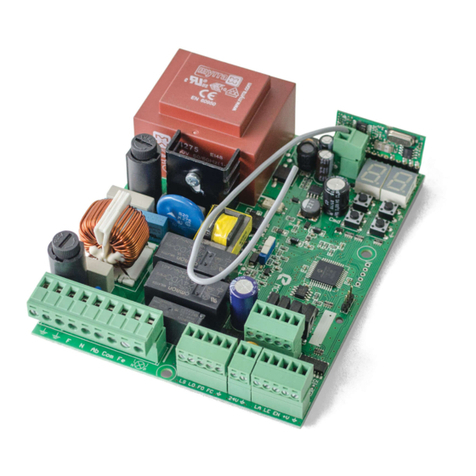
The MC18 is a 24V DC electronic control board, with a built-in radio control system, develo-
ped for the automation of shutters.
. THE CONTROL BOARD
TECHNICAL CHARACTERISTICSCONNECTION OF COMPONENTS TO THE CONTROL BOARD
• Output for motors 24Vdc 2 x 50 W max.
• Signal light output 24Vdc 3 W max.
• Power supply for photocell 24Vdc 3 W max.
• Working temperature -20 to +60 °C
• Built-in radio receiver 433,92 Mhz
• OP remote controls 12-18 Bit or Rolling Code
• Memory for remote controls 5
• Dimensions 110x121x47 mm.
• Transformer power supply 230V/20V 30VA (up to 1400mm) or 230V/50VA (over 1400mm)
CN1
01 • Input 20Vac 30/50 VA
02 • Input 20Vac 30/50 VA
03 • Output + 24V Motor 1
04 • Output - 24V Motor 1
05 • Output + 24V Motor 2
06 • Output - 24V Motor 2
CN2
01 • 12Vdc encoder power supply (do not use)
02 • Motor 1 encoder signal input (do not use)
03 • Motor 2 encoder signal input (do not use)
04 • GND encoder power supply (do not use)
05 • Photocell power supply + 24Vac 3W
06 • Photocell power supply (GND)
07 • Flashing light output + 24Vdc
08 • Common GND
09 • Safety device input (NC)
10 • Opening button Input (NA)
11 • Common GND input
12 • Closing button Input(NA)
FUSE
1A
TRANSFORMER
230V/20V
30VA
(see model)
50VA
(see model)

5A 5B
ENEN
. THE CONTROL BOARD
PRECONFIGURATION INDICATIONS
LEDS
T. R. CH • Closing delay (page 6B)
T. R. AP • Open delay (page 6A)
T. PAUSA • Automatic closing time
T. MOT • Motor working time programming (page 5B), slow-speed (page 7B)
CODE • Remote control programming (page 5A), close button configuration (page 7A).
CN3
01 • Antenna input (mass)
02 • Antenna input (hot pole)
CN2
Photocells:
05 and 06 • This circuit allows powering photocells.
OPENING: nothing happens; CLOSING: reverses the movement.
Flashing light:
07 and 08 • This output (24V DC 3W max) allows the connection of a flashing light to
identify the automation status.
CLOSED: OFF; OPEN: ON; IN MOVEMENT: ON.
Security devices:
09 and 11 • This circuit allows the connection of all types of safety devices, such as
photocells, safety edges, etc.
This device intervenes only when closing the shutter and, whenever activated, it
reverses the direction of movement of the automatism.
Note: If not used, you must have a Shunt (DS/ )
• PROGRAM THE CONTROL BOARD SEL/SET BUTTONS
SEL button: Selects the function to be changed. The selection is identified by
the flashing of the LED corresponding to the currently selected function.
By pressing the SEL button several times, you will cycle through the various
functions to be programmed. The selection remains active for 10 seconds, after
which the control board returns to its original state (no active selection).
SET button: Programs the selected function using the SEL button.
SET
SEL
The SET button can be replaced by a remote control, as long as it is programmed.
. THE CONTROL BOARD
OPERATIONAL CHARACTERISTICS :
Operation with remote control buttons:
• The open button will open until the factory set time expires.
• When the shutter is opening, if you press the opening button, the window movement is automatically
interrupted (the same happens when closing).
If you press a button opposite to the movement of the shutter, the movement reverses.
Operation with remote control:
• The first pulse opens the shutter until the end of the motor time. The second impulse closes the
shutter.
When the shutter is opening, if you press the remote control before the motor time is up, the shutter
movement is automatically stopped. If you press the remote control again, the shutter will move in the
opposite direction.
The control board allows the electrical supply and the connection of photocells. The intervention
of photocells in the opening phase is not taken into account, in the closing phase it causes the
inversion of the movement.
PHOTOCELLS
The control board is equipped with a VR1 regulation device to adjust the power and speed of
the motors, which are fully managed by the microprocessor. Adjustment can be made within
a range of 50% to 100% of maximum force. For each movement, there is an initial start-up,
powering the motor for 2 seconds at maximum power, even if the motor force setting is
changed.
MOTOR FORCE AND SPEED ADJUSTMENT
ATTENTION:A variation of the VR1 regulation device requires the repetition of
the T. MOT programming procedure, since the maneuver and slow-speed times
may vary.

6A 6B
ENEN
. THE CONTROL BOARD
The control board is equipped with a VR2 adjustment device to adjust the sensitivity needed
to detect the obstacle, which is fully managed by the microprocessor.
Its adjustment can be made with a reaction time that varies between a minimum of 0.1
seconds and a maximum of 3 seconds.
OBSTACLES DETECTION
ATTENTION: Obstacle detection works as follows: During opening - if it encounters
an obstacle, it reverses for 2 seconds; During closing - if it encounters an obstacle, it
reverses the maneuver completely until the point of total opening.
NOTE: In the last 5 sec. of maneuver the reaction to the obstacles is simply to stop.
The motor slow-speed function is used to prevent the shutters from hitting at high speed at
the end of the opening and closing phase.
During motor time programming (see main menu), the control board also allows program-
ming the slow-speed at the desired points (before total opening and closing).
If the "Automatic programming" function is used, the "slow-speed" function must be activa-
ted (see extended menu 1).
SLOWSPEED
The control board allows the connection of a 24Vdc 3 W max. to show the state of automation.
The light is off when the automation is closed, and remains on when moving or open.
SIGNAL LIGHT
. PROGRAMMING MAIN MENU
MAIN MENU
LED LED OFF LED ON
• CODE No code Code inserted
• T. MOT Motor time 30 sec. Programmed time
• T. PAUSA No automatic closing With automatic closing
• T. R.AP No opening delay Programmed time
• T. R.CH No closing delay Programmed time
MAIN MENU
This is the main menu of the MC18 control board, where you have access to the most important
functions of its operation. The control board is supplied with the main menu active.
The control board only accepts Dip-Switch or Rolling Code MOTORLINE remote controls, and
has a maximum capacity of 5 remote controls. When trying to program the 6th remote control,
all programming LEDs will flash simultaneously, indicating full memory.
There are 2 methods to program new remote controls:
Method A: 1 button to open and close
01 • Press the SEL button as many times as necessary until the CODE LED starts flashing.
02 • Press the remote button you want to program for 1 second.
03 • The LED starts flashing fast, release the button and wait for the LED to stop flashing.
Method B: 1 button to open + 1 button to close
01 • Press the SEL button as many times as necessary until the CODE LED starts flashing.
02 • Press the button of the remote you want to program the opening for one second.
03 • The LED starts flashing fast, now press the close button or wait for it to stop flashing.
To delete all configured remote controls:
01 • Press the SEL button as many times as necessary until the CODE LED starts to flash.
02 • Press the SET button until the CODE LED turns OFF. All remote controls are erased.
CODE | REMOTE CONTROL PROGRAMMING
01 • Connect all accessories according to the wiring diagram (page 4A).
02 • Connect the automation to a 230Vac power supply.
03 • In EXTENDED MENU 1, check that the slow-speed is ON/OFF and set it as you like.
04 • Make an automatic course programming - EXTENDED MENU 2 (page 9B).
05 • Program a remote control (page 6B).
ESSENTIAL STEPS FOR INSTALLATION

7A 7B
ENEN
. PROGRAMMING MAIN MENU
MAIN MENU
5 • T. MOT. LED flashes slowly and the
motor starts moving at slow-speed. 10 • T. MOT. LED flashes slowly and the
motor starts moving at slow-speed.
6 • Press SET to finish opening when it
reaches the stopper. 11 • Press SET to finish opening when it
reaches the stopper.
The control board is provided with a working time set to 30 seconds without slow-speed.
If you want to change the working time of motors 1 and 2, the shutter must be closed.
T. MOT | PROGRAMMING THE WORKING TIME OF THE MOTORS MIN. MAXIMUM
4 • Press SET at the desired point for slow-speed. 9 • Press SET at the desired point for slow-speed.
2
•
Press SET.
1
•
Press the SEL
button as many times
as necessary until
the T.MOT LED starts
flashing.
7
• LED T. MOT. flashes regularly again.
3
•
Motor 1 starts opening. 8
•
Motor 2 starts opening.
In case you want slow-speed, you must go to the Extended Menu 1 and activate
the slow-speed (T.MOT., pg 8B).
1º OPENING TIME PROGRAMMING
Motor 1 Motor 2
. PROGRAMMING MAIN MENU
The control board allows automatic closing after a certain waiting time, up to a maximum of
4 minutes.
The control board is supplied by the manufacturer with this function disabled.
Programming:
01
•Press the SEL button as many times as necessary until the T.PAUSA LED starts flashing.
02
•Press the SET button, wait as long as you want and press SET again.
NOTE • the time interval between pressing SET the 1st time and the 2nd time, represents the
time that the motor will wait in opening until it starts automatic closing.
03
•The T. PAUSA LED will be ON, signaling the success of the operation.
Delete:
01
•Press the SEL button as many times as necessary until the T.PAUSA LED starts flashing.
02
•Press SET twice in less than 2 seconds.
03 • The T. PAUSA LED. will turn OFF, signaling the success of the operation.
T. PAUSA | PROGRAMMING THE AUTOMATIC CLOSE TIME MIN. MAXIMUM
MAIN MENU
With this function, you can delay the start of opening of motor 2 by up to 30 seconds in re-
lation to motor 1.
The control board is delivered without opening delay.
Programming:
01
•Press the SEL button as many times as necessary until the T.R.AP LED starts flashing.
02
•Press the SET button, wait the amount of time you want and press SET again.
NOTE • the time interval between pressing SET the 1st time and the 2nd time represents the
time that motor 2 will delay in relation to motor 1.
04
•The T.R.AP LED will be ON, signaling the success of the operation.
Delete:
01
•Press the SEL button until the T.R.AP LED starts flashing.
02
•Press the SET button twice within 2 seconds.
03
•The T.R.AP LED will turn OFF, signaling the success of the operation.
T. R. AP | OPENING DELAY PROGRAMMING SEC. MAXIMUM
2º CLOSING TIME PROGRAMMING
Motor 2 Motor 1
15 • T. MOT. LED. flashes slowly and the
motor starts moving at slow-speed. 22 • Closing completes when reaching the
stopper.
16 • Closing completes when reaching the
stopper. 23 • Press SET to finish.
14 • Press SET at the desired point for slow-speed. 21 • T. MOT. LED flashes slowly and the
motor starts moving at slow-speed.
12
• T. MOT. LED flashes regularly again.
19
•
Motor 1 starts closing.
13
•
Motor 2 starts closing. 20
• Press SET at the desired point for
slow-speed.
17 • Press SET to finish.
18
• T. MOT. LED flashes regularly again. 24 • LED T. MOT. will stop flashing, wait for
all LEDs to stop flashing.

8A 8B
ENEN
. PROGRAMMING MAIN MENU
MAIN MENU
T. R. CH | CLOSING DELAY PROGRAMMING SEC. MAXIMUM
With this function, you can delay the start of closing of motor 1 by up to 30 seconds in rela-
tion to motor 2.
The control board is delivered without closing delay.
Programming:
01
•Press the SEL button as many times as necessary until the T.R.CH LED starts flashing.
02
•Press the SET button, wait as long as you want and press SET again.
NOTE • the time interval between pressing SET the 1st time and the 2nd time represents the
time that motor 1 will delay in relation to motor 2.
03
•The T. R. CH LED will be ON permanently, signaling the memorization of the delay time
between motor 1 and motor 2.
Delete:
01
•Press the SEL button until the T.R.CH LED starts to flash.
02
•Press the SET button twice within 2 seconds.
03
•The T.R.CH LED will turn OFF, signaling the success of the operation.
RESET FACTORY SETTING
If it is necessary to reset the factory settings, press the SEL and SET buttons simultaneously.
All LEDs will turn red and then turn OFF. All red LEDs will light up and then turn off, with a
complete reset to factory parameters.
. PROGRAMMING EXTENDED MENU
EXTENDED MENU
The control board is supplied by the manufacturer with an extended menu 1, which allows
access to more functions of the control board.
To access the options of the extended menu 1, follow the instructions below:
01 •
Press and hold the SET button for 5 seconds and the T.R.AP LED and T.R.CH LED will flash
alternately for 30 seconds.
If it is more than 30 seconds without selecting an option from the Extended
Menu 1, it returns to the Main Menu.
EXTENDED MENU 1
LED LED OFF LED ON
• CODE Separate open and close buttons Closing button in
step-by-step mode
• T. MOT Slow-speed OFF Slow-speed ON
• T. PAUSA DS=inverts on opening DS=stops on opening and
closing
• T. R. AP ON/OFF flash alternately
• T. R. CH ON/OFF flash alternately
Inputs nº10 and nº12 of CN2 are configured as automation opening and closing buttons. It is
possible to configure the button at input nº12 for a button with cyclic operation: OPEN - STOP
- CLOSE (step by step). Input button nº10 continues to control opening only.
In order to change the operation of the buttons to:
- opening button: continue to be opening only;
- closing button: to become a step-by-step button (cyclic) OPEN - STOPS - CLOSE.
Follow the following steps:
01
•
Access the extended menu 1 (page 8B).
02
•Press the SEL button as many times as necessary until the CODE LED starts flashing.
03
•Press SET to confirm.
04
•The CODE LED will turn ON/OFF and the operation is complete.
05
•If you want to go back to the two separate buttons, repeat the operation again and turn
off the LED.
CODE | PUSH BUTTON CONFIGURATION

9A 9B
ENEN
. PROGRAMMING EXTENDED MENU
EXTENDED MENU
T. MOT | SLOWSPEED
With this function, you can activate/deactivate the slow-speed of the motors, both when ope-
ning and when closing.
Activate slow-speed - LED on / Deactivate slow-speed - LED off:
01
•
Access the extended menu 1 (page 8B).
02
•Press the SEL button as many times as necessary until the T.MOT LED starts flashing.
03
•Press SET to confirm.
04
•The T.MOT LED will light up and the operation is completed.
05
•If you want to deactivate the slow-speed, repeat the operation again and turn off the
LED.
T. PAUSA | PHOTOCELL OPERATING LOGIC
The control board is factory configured to ignore the photocells when opening and invert the
movement of the motors when closing.
In this function, you can change the action of the photocell, starting to stop when it is
activated when opening and closing.
Photocells stop operating during opening and closing - LED on / Photocells cause inversion
only during closing - LED off:
01
•
Access the extended menu 1.
02
•Press the SEL button as many times as necessary until the T.PAUSA LED starts flashing.
03
•Press SET to confirm.
04
•The T.PAUSA LED will turn ON/OFF and the operation is complete. CODE | FUNCTION NOT USED
This function has no use, for that reason keep the LED off.
If you activate the function by accident, repeat the operation again and turn off the LED.
. PROGRAMMING EXTENDED MENU
EXTENDED MENU
EXTENDED MENU 2
LED LED OFF LED ON
• CODE
(function not used) Keep LED off Keep LED off
• T. MOT Automatic PGM OFF Automatic PGM ON
• T. PAUSA Automation of 2 motors Automation of 1 motor
• T. R. AP ON/OFF flashes simultaneously
• T. R. CH ON/OFF flashes simultaneously
The control board is provided by the manufacturer with an extended menu 2, which allows
access to more functions of the control board.
To access the options of the extended menu 2, follow the instructions below:
01 •
Access the extended menu 1 (p. 8B).
02 • Press and hold the SET button for 5 seconds and the T.R.AP LED and T.R.CH LED will flash
simultaneously.
If you are in Extended Menu 2 for more than 30 seconds without selecting an
option, you will return to the Main Menu.

10A 10B
ENEN
• If the motor moves in the opposite direction, turn OFF the power supply and change the motor wires.
• Keeping SET always pressed, until the end of programming, the control board will open and close
completely.
• The control board will increase the slow-speed duration by 15% of the recognized course in the
automatic programming.
• You can also use a remote control instead of the SET button (previously memorized in the control board).
. PROGRAMMING EXTENDED MENU
EXTENDED MENU
T.MOT | AUTOMATIC PROGRAMMING
T. PAUSA | AUTOMATION / MOTORS
The control board makes it possible to automatically program the course without having to
give slow-speed and stop orders.
For automatic programming (LED on) / Programming off (LED off):
01 • Unlock the motor, place the shutter halfway and lock the motor again.
02 • Access the Extended Menu 1 (p. 8B).
03 • Access the Extended Menu 2 (p.9B).
04 • Press the SEL button as many times as necessary until the T.MOT LED starts flashing.
05 • Press SET continuously (do not release the button until you finish the following maneuvers).
06 • Motor 2 will close to the limit switch or stopper.
07 • Motor 1 will close to the limit switch or stopper.
08 • Motor 1 will open to the limit switch or stopper.
09 • Motor 2 will open to the limit switch or stopper.
10 • Motor 2 will close to the limit switch or stopper.
11 • Motor 1 will close to the limit switch or stopper and automatic programming is complete.
12 • Release the SET button.
To facilitate installation, the control board has two standard configurations for 1 or 2 motors.
In the standard configuration, the control board has the typical management of a 2-motor
automation. If you need to activate the standard management of a 1-motor automation,
proceed as follows:
01 • Access the Extended Menu 2 (p. 9B).
02 • Press the SEL button as many times as necessary until the T.PAUSA LED starts flashing.
03 • Press SET once.
04 • The T.PAUSA LED will be permanently ON and the process is complete.
05 • Repeat the operation if you want to restore the previous configuration and turn off the LED.
. PROGRAMMING EXTENDED MENU
EXTENDED MENU
SLOWSPEED PROGRAMMING
The control board allows you to program the slow-speed of the motors.
It is possible to choose between 3 levels of speed, each combination of lit LEDs
corresponds to a level.
In the factory setting the selected level is level 1.
01
•
Access the extended menu 1 (p. 8B).
02 •
Access the extended menu 2 (p. 9B).
03 •
Access the extended menu 3 (p. 10B).
04
•Press the SEL button to select the desired speed level by lighting LEDs, while the others
will flash.
05
•Press SET to confirm.
The control board is provided by the manufacturer with the Extended menu 3, which allows
access to more functions of the control board.
If you want to change the speed of the slow-speed power executed by the control board,
follow the instructions below:
01 •
Access the extended menu 2 (p. 9B).
02 • Press and hold the SET button for 5 seconds and the T.R.AP LED and T.R.CH LED will flash
alternately and then simultaneously.
03 • Use the SEL and SET buttons to select the desired option for 30 seconds.
EXTENDED MENU 3
LEVEL LED ON
• 1 Slower (slow-speed) CODE
• 2Medium (slow-speed) CODE - T.MOT
• 3 Faster (slow-speed) CODE – T.MOT – T. PAUSA
• T. R. AP ON/OFF flash alternately/simultaneously
• T. R. CH ON/OFF flash alternately/simultaneously
If you are in Extended Menu 3 for more than 30 seconds without selecting an
option, you will return to the Main Menu.

11 EN
INSTRUCTIONS FOR SPECIALIZED TECHNICIANS
. TROUBLESHOOTING
INSTRUCTIONS FOR END CONSUMERS
Anomaly Procedure Behavior Procedure II Find the source of the problem
• Motor does
not work • Check that the
230V power supply
is connected to the
automation and that
the fuse is working
correctly.
• Still not working • Consult a qualified
MOTORLINE technician. 1• Remove the mechanism cover;
2• Measure the 20V output of the transformer to detect the location of the fault;
A) It has 20V:
1• Check that the control board is supplying the motor to detect whether the fault is in the motor or in the control board, measuring the output from
the control board to the motors. Replace the damaged component or send it to service for diagnosis and repair.
B) It does not have 20V:
1• Check the 230V input of the transformer. If you have 230V the problem is with the transformer. If not, the problem is with the fuse, electrical cables
or the electrical current itself. Check all systems.
• Motor does
not move but
makes noise
• Check if there are
any mechanical
problems with the
shutter.
• Is the shutter
stuck? • Consult a qualified
MOTORLINE technician. • Check all axes and movement systems associated with the shutter and automation to find out what the problem is.
• Does the shutter
move easily? • Consult a qualified
MOTORLINE technician. • Turn OFF the motors of the control board and test them by connecting directly to a V battery to find out if it is faulty;
• If the motors work, the problem is with the control board. Remove it and send it to technical services for diagnosis;
• If the motors do not work, remove them and send them to the technical services for diagnosis.
• Motor opens
but does not
close
1 • Check if there is any
obstacle in front of the
photocells;
2 • Check that the
photocells are working.
Pass your hand in front
and check if the relay
makes noise.
3 • Check if any of the
control devices (key
selector, pushbutton,
video intercom, etc.)
on the shutter are
stuck and sending a
permanent signal;
• The shutter opened
but did not close. • Consult a qualified
MOTORLINE technician. • Check that the LEDs are ON to confirm the existence of power supply;
• Check if the photocells are powered at the output of the control board;
• Try closing.
A) Closed:
• Problem is in one of these two systems. Put a SHUNT between DS and COM and send the photocells to technical services.
B) Did not close:
• Problem is in the motor or in the control board. Give the order to close the shutter while measuring the power output from the control board to
the motor. If it has V, the control board is working and the problem is with the motor.
• If there is no power, the problem is with the control board.
• Motor does
not make
complete
route
• Release the motor
and move the shutter
manually to check
the shutter for
mechanical problems.
• Did you encounter
problems? • Consult a qualified
MOTORLINE technician. • Check all axes and movement systems associated with the shutter and automation to find out what the problem is.
• Does the shutter
move easily? • Consult a qualified
MOTORLINE technician. • Check that the shutter tests were well done;
• Change the force on the Force and/or Sensitivity Potentiometer until the motor moves the shutter without inverting the direction;
• This adjustment must be made in such a way that the shutter, when encountering an obstacle, reverses;
• If even at the maximum power level the problem still persists, test the motor connected directly to a V battery to check if it has the power to
open/close the shutter completely;
• Change the force on the force and/or Sensitivity Potentiometer until the shutter reverses direction;
Table of contents
Other Motorline professional Controllers manuals
Popular Controllers manuals by other brands

Andover Controls
Andover Controls DCX 250 installation guide

InelControl
InelControl ORS-01IC Installation and operation manual

DSC
DSC PowerSeries Neo 3G8080I installation manual

MZ electronic
MZ electronic KOMPASS-8-868 Instructions for use

AL-KO
AL-KO SENSABRAKE Removal Instructions

Omnitronic
Omnitronic KEY-2816 user manual