Motorline MR14 Owner's manual

v1.1 REV. 12/2020
OPERATION / PROGRAMMING MANUAL EN
MR14
The MR14 receiver is a wireless receiver for managing multiple MX14 emitters.
When receiving information from the emitter, it communicates with the automation
control board via cable, so that the automation can be stopped or reversed.
TECHNICAL CHARACTERISTICS
• Power Supply -Vdc / -Vac
• ECO Inputs
/V
• Relay Vdc A/Vac .A
• Working frequency MHz
• Memory for emitters
• Reach in the open m
• Dimension
x x (mm)
• IP
IP
AES encryption
1
3
Basic operation:
Dipper 1 → ON;
Dipper 2 → OFF;
Dipper 3 → ON.
ECO NORMAL
ACTIVED
BUZZER DEACTIVATED
BUZZER
1
•
2
•
3
•
NC
COM
NO
Relay output NO channel
>the output is active when any channel 1 emitter is in error
(ex: Door hit an obstacle, communication failed or the battery ran out).
The NC or NO output must be connected to the control board.
4
•
5
•
6
•
NC
COM
NO
Relay output NO channel
>the output is active when any channel 2 emitter is in error
(ex: Door hit an obstacle, communication failed or the battery ran out). The NO
or NC output must be connected to the control board.
7
•
8
•
9
•
10 •
CH1
COM
CH2
COM
/V mode input
>used to activate channel 1 or 2 in ECO mode (Dipper 1 OFF). The control
board must activate this input when the door starts to move.
11
•
12
•
+
-
/ Vdc/ac power supply
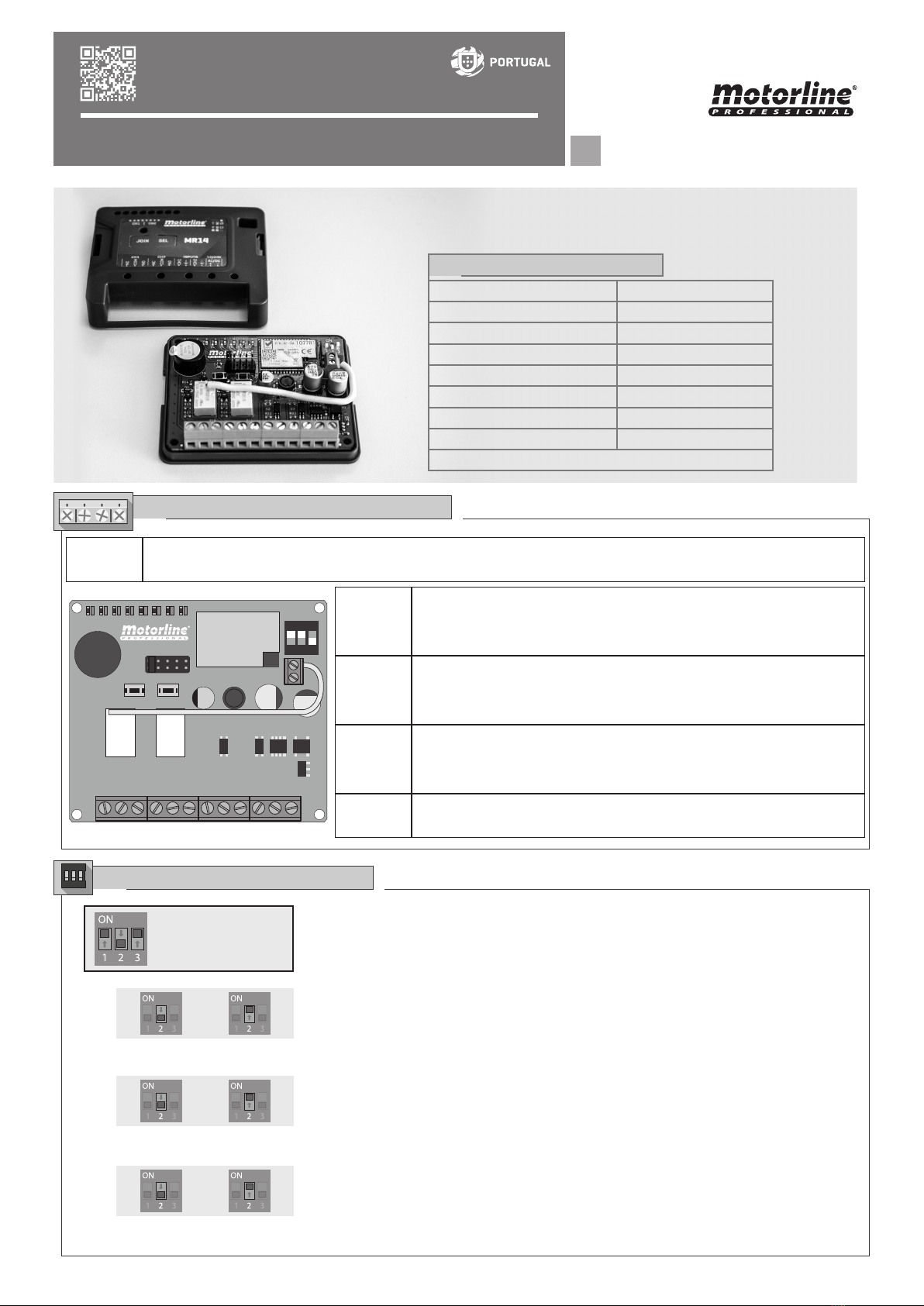
LEDs
LED, LED, LED e LED - memory position indicators to be programmed for channel
1 2 3
ON
NC COM NO NC COM NO CH1 COM CH2 COM + -
LED1 LED2 LED3 LED4 LED5 LED6 LED7 LED8
JOIN SEL
1 2 3 4 5 6 7 8 9 10 11 12
INPUTS / OUTPUTS AND LEDS
DIPPER
1 • Transmission mode
• OFF – ECO mode
> With ECO mode, devices will only communicate with each other when the automation is in
operation (opening or closing), in order to save energy.
To use this mode, it is necessary to connect the control board to the MR14 CH1 and / or CH2
inputs. When the door is stopped, communication takes place approximately every 30 seconds.
With the door moving, it will be done in intervals of 300 to 600 milliseconds.
•ON – NORMAL mode
> In this mode, communication is always done at intervals of 300 to 600 milliseconds, ignoring
energy savings.
As such, it is not necessary to connect the control board to the MR14 CH1 and / or CH2 inputs.
2 • Operation of CH1 and CH2 inputs (ECO mode)
> Select the desired status for the CH1 and CH2 inputs information, paying attention to the
settings of the operator control board.
• OFF – NO (MR14 and MX14 only communicate when the circuit is closed);
•ON – NC (MR14 and MX14 only communicate when the circuit is opened).
3 • Activate buzzer (audible alarm)
• OFF – Buzzer Actived;
•ON – Buzzer deactivated.
2
NO NC

20mm
81mm
66mm
BUTTONS AND LEDS
SEL → BUTTON TO SELECT THE EMITTER POSITION TO ADD/CHANGE:
>The selected LED is flashing;
>Each click increases a position, if you pass the last position it returns to LED ;
>If you do not press any button for seconds, the selected LED turns off and is no
longer in "selection mode".
JOIN → Button to enter or exit the "add emitter" mode:
>Press this button after selecting the position to add/change;
>To exit without adding a new emitter, press this button again.
• LED 1 to 8 → MEMORY POSITION INDICATORS TO PROGRAM:
ON – Emitter programmed in this position;
OFF – Free position;
Blink – Emitter programmed, but with error.
• LED JOIN → MEMORY POSITION INDICATORS TO PROGRAM:
ON – Programming mode active;
OFF – Programming mode inactive.
PROGRAMMING EMITTER:
1
• Press SEL button to select the position where you want to program the emitter.
2
• Press the JOIN button to open the selected position (the position LED will flash quickly)
3
• Press the JOIN button of the desired emitter.
4
• The position LED stops flashing and stays on, signaling the success of the operation.
NOTE • If a emitter is already stored in that position, the new emitter will replace the previously programmed emitter.
DELETE EMITTER:
1
• Press the emitter's JOIN button until the transmitter's JOIN LED flashes once.
NOTE • To delete when there is no communication between devices:
1
•
Press SEL button to select the position you want to delete.
2
•
Press the JOIN button to open the selected position (the position LED will flash quickly).
3
•
Press the JOIN button again to delete the emitter from that position.
4
•
The position LED stops flashing and goes off, signaling the success of the operation.
1 2 3
ON
NC COM NO NC COM NO CH1 COM CH2 COM + -
LED1 LED2 LED3 LED4 LED5 LED6 LED7 LED8
JOIN SEL
APPLICATION INSIDE THE MOTOR:
>
Insert the device into the motor cover, to facilitate
connections to the control board and to avoid
infiltration of moisture.
INSTALLATION:
>
The device can be applied in other locations.
Secure with screws.
NOTE
•
It is not advisable to install inside an iron
box as it can create noise in the communication.
PRODUCT INSTALLATION

RY24V G B
12 3 4 5
V+
R
G
B
RG
NO
987654321
NC
INHI
FORCE TILT
PROG JOIN
GND
ANT
8K2
PV
1 2 3
ON
NC COM NO NC COM NO CH1 COM CH2 COM + -
LED1 LED2 LED3 LED4 LED5 LED6 LED7 LED8
JOIN SEL
1 2 3 4 5
ENLELA +V
1 2
24V
1 2
24V
1 32 4 5
ENLELA +V
1 32 4 5
24V YRGB
Check the manual for your control board to identify the entries corresponding to the one indicated in the diagram.
1 • LA → Security band input
2 • LE → Photocells input
3 • (not used)
4 • (not used)
5 • COM
1 •24V output (minimum → 100mA)
2 •COM
1 • 24V → 24V output
2 • (not used)
3 • R → 0V output - activated
during closing maneuvers
4 • G → 0V output - activated
during opening maneuvers
5 • B → 0V output - activated
during pause time
Dry contact safety
devices NO
Dry contact safety
devices NC
If you do not use,
place a shunt.
Signal inhibitor
• When closed (NC),
the emitter will ignore
signals from inputs
k (-) and NO / NC
(--)
NOTE • dipper 2 must
be OFF
k resistive safety rubber
• To use, remove the resistance
that comes from the factory at
inputs and .
• If you do not intend to use a
safety band, this resistance must
remain in place. Solar panel
CONNECTION SCHEME
RGB Light
MR1Control board
MX1
Other Motorline Receiver manuals