manuals.online logo
Brands
  1. Home
  2. •
  3. Brands
  4. •
  5. Delta
  6. •
  7. Touch Panel
  8. •
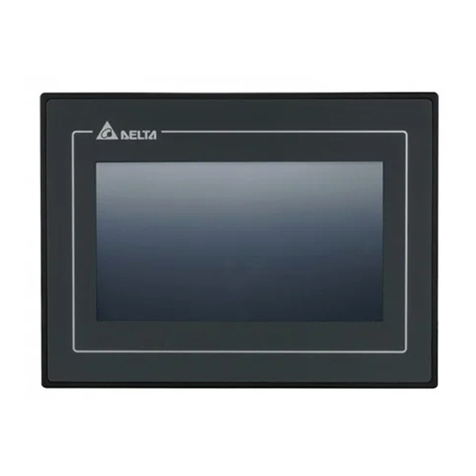
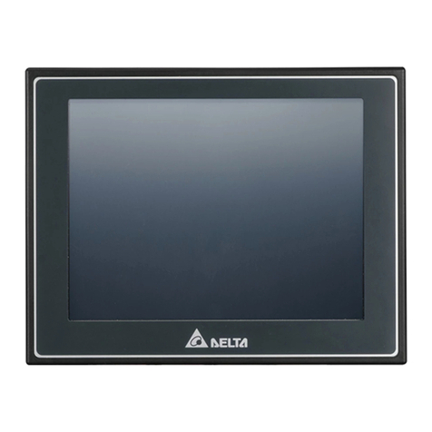
  9. Delta DOP-H07 Series User manual

Delta DOP-H07 Series User manual

DOP-H
07
High Color‧Motion Inside‧
User-Friendly HMI Products
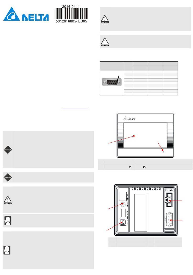
Instruction Sheet
(1) Preface
Thank you for purchasing DOP-H07 of Delta. This instruction sheet will be helpful in the installation, wiring and inspection
of Delta HMI product. Before using the product, please read this instruction sheet to ensure correct use. You should
thoroughly understand all safety precautions before proceeding with the installation, wiring and operation. Place this
instruction sheet at a safe location for future reference. Please observe the following precautions:
Install the product in a clean and dry location free from corrosive and inflammable gases or liquids.
Ensure that all wiring instructions and recommendations are followed.
Ensure that HMI is correctly connected to the ground. The grounding method must comply with the electrical
standard of the country (Please refer to NFPA 70: National Electrical Code, 2005 Ed.).
Do not modify or remove wiring when power is applied to HMI.
Do not touch the power supply during operation. Otherwise, it may cause electric shock.
If you have any questions during operation, please contact our local distributors or Delta sales representatives.
The content of this instruction sheet may be revised without prior notice. Please consult our distributors or download the
latest version at http://www.delta.com.tw/ia.
(2) Safety Precautions
Carefully note and observe the following safety precautions when inspecting, installing, operating, maintaining and
troubleshooting.
Installation

Comply with quick start for installation. Otherwise it may cause equipment damage.
Do not expose the product with the environment which containing water, corrosive gas, inflammable
gas, etc. Or it may result in electric shock, fire, or explosion.
Do not install the product in a location where temperatures will exceed specification for the HMI.
Failure to observe this caution may result in abnormal operation or damage the product.
This is KCC Class A product and has obtained the registration. It is for commercial or industrial use. If
it is purchased or sold by mistake, please exchange it for home use which meets the requirement of
KCC Class B.
Do not use this product as an alarm device for disaster early warning that may result in personal injury,
equipment damage, or system emergency stop.
Wiring
Connect the ground terminals to class-3 ground system (Ground resistance should not exceed 100Ω).
Improper grounding may result in communication error, electric shock or fire.
Operation
When designing HMI programs, if the interface is not programmed well, it may cause the abnormal
operation. Therefore, in order to prevent personal injury or equipment damage, be ensured the
communication error caused by the interface, controller or equipment would not lead to the
malfunction of the product.
Please backup the screen data and HMI programs in case the data is lost.
When not in use, please place the HMI at a flat surface or use the hook on the back to hang it properly
to avoid risks of falling or crash.
Do not modify wiring during operation. Otherwise it may result in electric shock or personal injury.
Never use a sharp object to touch or hit the screen as doing this may damage the screen and cause
malfunction of HMI.
Maintenance and Inspection
Do not touch any internal or exposed parts of the HMI as this may damage the product or cause
electric shock.
Wait at least 10 minutes after power is removed before touching any HMI terminals or performing any
wiring and/or inspection.Or the residual voltage may cause electric shock.
Wiring Method
Do not use a voltage that will exceed specification for the HMI. Failure to observe this caution may
result in electric shock, fire.
If any cable is forced removed, please make sure to check the connection again and then restart.
Communication Wiring
Comply with communication wiring specification for wiring.
To avoid noise and interference, the communication cable, all power cables, and motor power cable
should be placed in separate conduits.
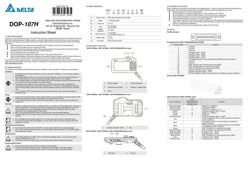
(3) Model Explanation
DOP - H 07 S 4 6 5
(1) (2) (3) (4) (5) (6) (7)
(1) Product
Name
DOP: Delta Operator Panel(HMI)
(2) Series H: Handle (Hand-held Series)
(3) Size 07: 7.0"
(4) Type
E: Ethernet
S: Standard
(5) Display
Resolution
4: WVGA
(6) External
Device
Code Handwheel SD Reserve
2 ●
6 ●●
(7) Cable
Length
5: 5 m A: 10 m
(4) Parts Names
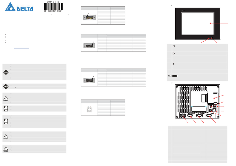
DOP-H07S42x / DOP-H07S46x / DOP-H07E42x / DOP-H07E46x (Front View)
A LED Power Indicator B Function Keys
C Touch Screen / Display D Emergency Stop
E Handwheel
DOP-H07S42x / DOP-H07S46x / DOP-H07E42x / DOP-H07E46x (Rear View)
A 3-Position Operation Switch
B Cable
DOP-H07S42x / DOP-H07S46x / DOP-H07E42x / DOP-H07E46x (Bottom View)
(5) Ambient Conditions of Installation and Storage
The product should be kept in the shipping carton before installation. In order to retain the warranty coverage, the HMI
should be stored properly when it is not to be used for an extended period of time. Some storage suggestions are:
Store in a clean and dry location
Store within an ambient temperature range of -10°C to +60°C (-14°F to 140°F).
Store within a relative humidity range of 10% to 90% and in a non-condensing environment.
Do not store the HMI in a place subjected to corrosive gases and liquids.
Correctly packaged and placed on a solid and durable surface.
The ambient conditions of installation should NOT include: over-heat device; water drop, vapor, dust and
oily dust; corrosive and inflammable gas and liquid; airborne dust and metal particles; interference of
electromagnetic noise; should have solid foundation and no vibration;
(6) Wiring Method
Wire of DOP-H07E4xx
Wire of DOP-H07S4xx
DOP-H07x4 Series Cable Definition
DOP-H07E4xx
Pin of the Quick
Connector
DOP-H07x4xx
Color of Skinned
Wire
Corresponding
Wire (wire with
the same letter
are wired
together)
Function
1 H07E: RJ45 pin1
H07S: White /
Orange
A DOP-H07E: LAN RD+
DOP-H07S: RS422 TX+
RS485 D+
2
White / Black
DOP-H07S: SG(RS422, RS485)
3 H07E: RJ45 pin3
H07S: White /
Green B DOP-H07E: LAN TD+
DOP-H07S: RS422 RX+(with a label marked
12)
4
Brown
3-Position Operation Switc – NO(A)
5 H07E: RJ45 pin2
H07S: Orange A
DOP-H07E: LAN RD-
DOP-H07S: RS422 TX-
RS485 D-
6 H07E: RJ45 pin6
H07S: Green
B DOP-H07E: LAN TD-
DOP-H07S: RS422 RX-
7
White / Brown
3-Position Operation Switch – NO(A)
8
Red
DC 24V
9
Black
0V
10
White
FGND (Power Ground)
11
Yellow
C
DOP-H07x46x only: Handwheel Output A
12
White / Yellow
C
DOP-H07x46x only: Handwheel Output B
13
White / Purple
D
Emergency Stop – NO(A)
14
White / Green
D
Emergency Stop– NO(A)
15 White / Red DOP-H07x46x only: External power input of
Handwheel
(< DC 24V)
16
Blue
E
Emergency Stop– NC(B)
17
White/Blue
E
Emergency Stop– NC(B)
A USB Slave B SD Card
A
A B
B
A
C
E
D
B

(7) Basic Inspection
Item Content
General Inspection
Periodically inspect the screws of the connection between the HMI and device.
Ensure the correct installation and the control panel should be free from airborne
dust, harmful gases or liquids.
Inspection before
operation
(power is not applied)
Make sure that all wiring is correct to avoid damage and malfunction.
Visually check and ensure that no unused screws, metal strips, any conductive or
inflammable materials are inside the HMI.
Lower electromagnetic interference when devices are influenced by it.
Ensure that the external applied voltage to HMI is correct and matched to the
controller.
Inspection before
operation
(power is applied)
Check if power indicator lights up.
Check if the communication among devices is normal.
Please contact our local distributors or Delta sales representative if there are any
abnormal conditions.
(8) Specifications
Model DOP-H07S42x DOP-H07S46x DOP-H07E42x DOP-H07E46x
LCD MODULE
Display
Type
7" TFT LCD (65535 colors)
Resolution 800 x 480 pixels
Backlight LED Back Light (less than 20,000 hours half-life at 25oC) (Note 1)
Display Size 154.08 x 85.92 mm
Operation
System Delta Real Time OS
MCU 32-bit RISC Micro-controller
Flash ROM Flash ROM 128 MB(OS System: 30 MB / Backup: 16 MB / User Application: 82 MB)
Backup Memory
(Bytes) 16 Mbytes ROM, 128 Kbytes SRAM
Buzzer Multi-Tone Frequency (2K ~ 4K Hz)/85 dB
Ethernet
Interface N/A 10/100 Mbps auto-sensing (with built-in isolated
power circuit) (Note 2)
Serial COM Port RS-422/RS-485 N/A
Memory Card SD / SDHC
USB 1 USB Client Ver 2.0
Emergency Stop
A-contact: 1 / B-contact: 1
Rated voltage: DC 30V
Maximum rated current: 1A
Minimum allowable load: DC 5V/1 mA
Complies with IEC60947-5-1, EN60947-5-1, IEC60947-5-5, EN60947-5-5, UL 508, and CSA C22.2
No.14, GB 14085.5
3-Position
Operation Switch
A-contact: 1
Rated voltage: DC 30V
Maximum rated current: 700 mA
Minimum allowable load:DC 3 V/5mA
Complies with EN/IEC60947-5-8, IEC60947-5-1, EN60947-5-1, JIS C8201-5-1, UL508, and CSA
C22.2 NO. 14
Applicable standards for use with ISO12100-1, -2/EN12100-1, -2, IEC60204-1/EN60204-1,
ISO11161/prEN11161, ISO10218/EN775, ANSI/RIA R15.06, ANSI B11.19
Handwheel N/A
Rated Voltage: <DC 24V
in
Resolution: 50(P/R)
Output Pulse: Square
Output Phase: A, B
Phase difference of A
and B: 90° ± 45°
Max. Frequency
response: 200 Hz
N/A
Rated Voltage: <DC
24V in
Resolution: 50(P/R)
Output Pulse: Square
Output Phase: A, B
Phase difference of A
and B: 90° ± 45°
Max. Frequency
response: 200 Hz
Function Key 15 Function Keys
Cable Length &
Type End of Model Name: 5-5M, A-10M
Perpetual
Calendar Built-in
Cooling Method Natural cooling
Safety Approval CE (Note 3)
Waterproof Level
of Panel Display N/A
Operation
Voltage ( DC +24V (±15%) (with built-in isolated power circuit)(Note 2)
Voltage
Endurance AC500V for 1 minute (between charging (DC24V terminal)
and FG terminals)
Power
Consumption 5.6 W (Note 4)
Backup Battery 3V lithium battery CR2450 × 1
Backup Battery
Life About 5 years or more at 25oC but subjects to the temperature and the conditions during usage.
Operation
Temperature 0oC ~ 40oC
Storage
Temperature -10oC ~ +60oC
Operating
Environment 10% ~ 90% RH【0 ~ 40oC】; 10% ~ 55% RH【41 ~ 50oC】; Pollution Degree 2
Vibration Conforms to IEC61131-2;
Continuous: 5Hz ~ 8.3Hz 3.5 mm, 8.3Hz ~ 150Hz 1G
Shock Conforms to IEC60068-2-27;
11ms, 15G Peak , X, Y, Z direction for 6 times
Dimension 257.4 x 170.3 x 71.8 (Emergency stop switch and hook are included.)
(W) x (H) x (D)
mm
Weight 750 g (cable excluded)
NOTE
1) The half-life of backlight is defined as original luminance being reduced by 50% when the maximum driving current
is supplied to HMI. The life of LED backlight shown here is an estimated value under 25oC normal temperature and
humidity conditions.
2) The withstand voltage of the isolated power circuit is 1500 V peak for 1 minute.
3) Some models are in the process of application to certification. For more information, please consult our distributors.
4) Power consumption of HMI is the power consumed when not connecting to any peripheral devices. The power
supply of which capacity is 1.5 ~ 2 times the power consumption is recommended to ensure normal operation.
5) DOPSoft , the program editor for DOP-H series products and user manuals can be downloaded at our website,
http://www.delta.com.tw/ia.
6) The content of this instruction sheet may be revised without prior notice. Please consult our distributors or
download the latest version at http://www.delta.com.tw/ia .
7) Isolated power supply is recommended.

This manual suits for next models

4

Other Delta Touch Panel manuals

Delta DIAVH-PPC193100 User manual

Delta

Delta DIAVH-PPC193100 User manual

Delta DOP-107EG User manual

Delta

Delta DOP-107EG User manual

Delta DOP-110DS User manual

Delta

Delta DOP-110DS User manual

Delta TP70P-211LC1T User manual

Delta

Delta TP70P-211LC1T User manual

Delta DOP-107SV User manual

Delta

Delta DOP-107SV User manual

Delta DOP-W127B User manual

Delta

Delta DOP-W127B User manual

Delta TP04G-AL User manual

Delta

Delta TP04G-AL User manual

Delta DOP-110IS User manual

Delta

Delta DOP-110IS User manual

Delta DOP-B08 User manual

Delta

Delta DOP-B08 User manual

Delta DIAVH-IPC003100 User manual

Delta

Delta DIAVH-IPC003100 User manual

Delta DOP-A User manual

Delta

Delta DOP-A User manual

Delta Vivitek NovoTouch EK653i User manual

Delta

Delta Vivitek NovoTouch EK653i User manual

Delta DOP-103WQ User manual

Delta

Delta DOP-103WQ User manual

Delta Vivitek NovoTouch EK653i User manual

Delta

Delta Vivitek NovoTouch EK653i User manual

Delta DOP-107H User manual

Delta

Delta DOP-107H User manual

Delta DOP-B10 Series User manual

Delta

Delta DOP-B10 Series User manual

Delta DOP-B03 User manual

Delta

Delta DOP-B03 User manual

Popular Touch Panel manuals by other brands

Philips 24BDL4151T/75 user manual

Philips

Philips 24BDL4151T/75 user manual

Icop PN8M-090T-P5A-N5GM user manual

Icop

Icop PN8M-090T-P5A-N5GM user manual

TCS TrainSpeed1 operating manual

TCS

TCS TrainSpeed1 operating manual

interactive scape st65-006 operating manual

interactive scape

interactive scape st65-006 operating manual

Bticino MyHOME 3488 instruction manual

Bticino

Bticino MyHOME 3488 instruction manual

Terasic VEEK-MT-C5SOC user manual

Terasic

Terasic VEEK-MT-C5SOC user manual

GREER Company MicroGuard manual

GREER Company

GREER Company MicroGuard manual

HomeSeer Technologies HST-IWAR7 installation guide

HomeSeer Technologies

HomeSeer Technologies HST-IWAR7 installation guide

ICOP Technology PPC-090T-APL-N4-4G user manual

ICOP Technology

ICOP Technology PPC-090T-APL-N4-4G user manual

harma AMX VARIA-SL80 quick start guide

harma

harma AMX VARIA-SL80 quick start guide

Winmate P Series quick start guide

Winmate

Winmate P Series quick start guide

Siemens POL8T5.70/STD Mounting instruction

Siemens

Siemens POL8T5.70/STD Mounting instruction

TC Electronic TouchMonitor TM7 user manual

TC Electronic

TC Electronic TouchMonitor TM7 user manual

AIS HMI?TCND0U?15AR?X00H HMI?TCND0U?07AR?X00H user manual

AIS

AIS HMI?TCND0U?15AR?X00H HMI?TCND0U?07AR?X00H user manual

Crestron Isys TPMC-4SM Operations & installation guide

Crestron

Crestron Isys TPMC-4SM Operations & installation guide

Avalue Technology ARC-1532-C1 Quick reference guide

Avalue Technology

Avalue Technology ARC-1532-C1 Quick reference guide

IEI Technology AFL-xxA-N270 series user manual

IEI Technology

IEI Technology AFL-xxA-N270 series user manual

AMX AXR-NWS Specifications

AMX

AMX AXR-NWS Specifications

manuals.online logo
manuals.online logoBrands
  • About & Mission
  • Contact us
  • Privacy Policy
  • Terms and Conditions

Copyright 2025 Manuals.Online. All Rights Reserved.